Random wanderings through Microsoft Azure esp. PaaS plumbing, the IoT bits, AI on Micro controllers, AI on Edge Devices, .NET nanoFramework, .NET Core on *nix and ML.NET+ONNX
The next step was to figure out how to configure a Pulse Width Modulation (PWM) output and an Analog Input so I could adjust the duty cycle and control the brightness of a Light Emitting Diode(LED).
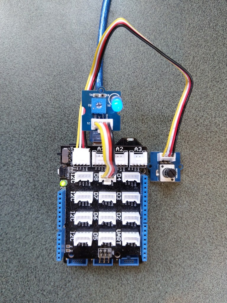
Netduino 3 ADC & PWN test rig
My test rig uses (prices as at Aug 2020) the following parts
 public class Program
   {
      public static void Main()
      {
         Debug.WriteLine("devMobile.Longboard.AdcTest starting");
         Debug.WriteLine(AdcController.GetDeviceSelector());

         try
         {
            AdcController adc = AdcController.GetDefault();
            AdcChannel adcChannel = adc.OpenChannel(0);

            while (true)
            {
               double value = adcChannel.ReadRatio();

               Debug.WriteLine($"Value: {value:F2}");

               Thread.Sleep(100);
            }
         }
         catch (Exception ex)
         {
            Debug.WriteLine(ex.Message);
         }
      }
   }
The nanoFramework code polls for the rotary angle sensor for its position value every 100mSec.
The setup to use for the Analog to Digital Convertor(ADC) port was determined by looking at the board.h and target_windows_devices_adc_config.cpp file.
//
// Copyright (c) 2018 The nanoFramework project contributors
// See LICENSE file in the project root for full license information.
//

#include <win_dev_adc_native_target.h>

const NF_PAL_ADC_PORT_PIN_CHANNEL AdcPortPinConfig[] = {

    // ADC1
    {1, GPIOC, 0, ADC_CHANNEL_IN10},
    {1, GPIOC, 1, ADC_CHANNEL_IN11},

    // ADC2
    {2, GPIOC, 2, ADC_CHANNEL_IN14},
    {2, GPIOC, 3, ADC_CHANNEL_IN15},

    // ADC3
    {3, GPIOC, 4, ADC_CHANNEL_IN12},
    {3, GPIOC, 5, ADC_CHANNEL_IN13},

    // these are the internal sources, available only at ADC1
    {1, NULL, 0, ADC_CHANNEL_SENSOR},
    {1, NULL, 0, ADC_CHANNEL_VREFINT},
    {1, NULL, 0, ADC_CHANNEL_VBAT},
};

const int AdcChannelCount = ARRAYSIZE(AdcPortPinConfig);
The call to AdcController.GetDeviceSelector() only returned one controller
The thread '<No Name>' (0x2) has exited with code 0 (0x0).
devMobile.Longboard.AdcTest starting
ADC1
After some experimentation it appears that only A0 & A1 work on a Netduino. (Aug 2020).
My PWM test harness
public class Program
{
   public static void Main()
   {
      Debug.WriteLine("devMobile.Longboard.PwmTest starting");
      Debug.WriteLine(PwmController.GetDeviceSelector());

      try
      {
         PwmController pwm = PwmController.FromId("TIM5");
         AdcController adc = AdcController.GetDefault();
         AdcChannel adcChannel = adc.OpenChannel(0);

         PwmPin pwmPin = pwm.OpenPin(PinNumber('A', 0));
         pwmPin.Controller.SetDesiredFrequency(1000);
         pwmPin.Start();

         while (true)
         {
            double value = adcChannel.ReadRatio();

            Debug.WriteLine(value.ToString("F2"));

            pwmPin.SetActiveDutyCyclePercentage(value);

            Thread.Sleep(100);
         }
      }
      catch (Exception ex)
      {
         Debug.WriteLine(ex.Message);
      }
   }

   private static int PinNumber(char port, byte pin)
   {
      if (port < 'A' || port > 'J')
         throw new ArgumentException();
      return ((port - 'A') * 16) + pin;
   }
}
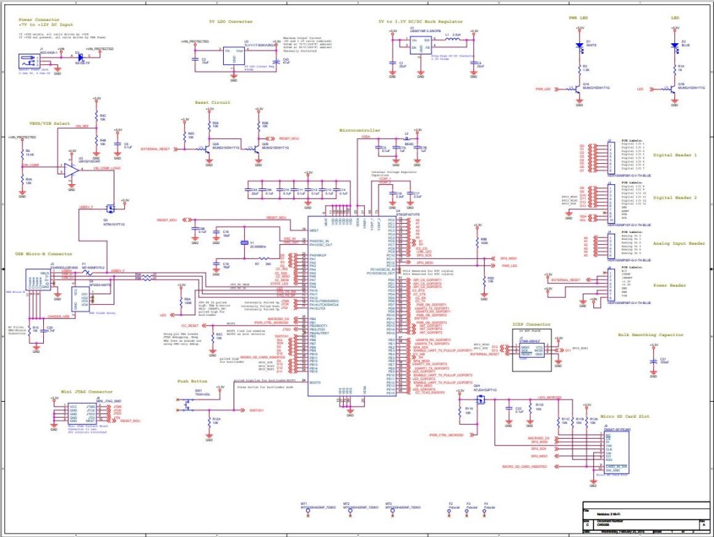
I had to refer to the Netduino schematic to figure out pin mapping
With my test rig (with easy access to D0 thru D8) I found that only D2,D3,D7 and D8 work as PWM outputs.
The nanoFramework SPI and interrupt port configuration (note the slightly different SPI port configuration)
public void Initialize(string spiPortName, int chipEnablePin, int chipSelectPin, int interruptPin, int clockFrequency = 2000000)
{
   var gpio = GpioController.GetDefault();

   if (gpio == null)
   {
      Debug.WriteLine("GPIO Initialization failed.");
   }
   else
   {
      _cePin = gpio.OpenPin(chipEnablePin);
      _cePin.SetDriveMode(GpioPinDriveMode.Output);
      _cePin.Write(GpioPinValue.Low);

      _irqPin = gpio.OpenPin((byte)interruptPin);
      _irqPin.SetDriveMode(GpioPinDriveMode.InputPullUp);
      _irqPin.ValueChanged += irqPin_ValueChanged;
   }

   try
   {
      var settings = new SpiConnectionSettings(chipSelectPin)
      {
         ClockFrequency = clockFrequency,
         Mode = SpiMode.Mode0,
         SharingMode = SpiSharingMode.Shared,
      };

      _spiPort = SpiDevice.FromId(spiPortName, settings);
   }
   catch (Exception ex)
   {
      Debug.WriteLine("SPI Initialization failed. Exception: " + ex.Message);
   return;
   }
The error handling of the initialise method is broken. If the some of the GPIO or SPI port configuration fails a message is displayed in the Debug output but the caller is not notified.
I’m using a Netduino 3 Wifi as the SPI port configuration means I can use a standard Arduino shield to connect up the NRF24L01 wireless module without any jumpers
Netduino 3 Wifi and embedded coolness shield
I have applied the PowerLevel fix from the TinyCLR and Meadow libraries but worry that there maybe other issues.
Based on my experiences porting the library to three similar platforms and debugging it on two others I’m considering writing my own compile-time platform portable library.
//---------------------------------------------------------------------------------
// Copyright (c) July 2020, devMobile Software
//
// Licensed under the Apache License, Version 2.0 (the "License");
// you may not use this file except in compliance with the License.
// You may obtain a copy of the License at
//
//     http://www.apache.org/licenses/LICENSE-2.0
//
// Unless required by applicable law or agreed to in writing, software
// distributed under the License is distributed on an "AS IS" BASIS,
// WITHOUT WARRANTIES OR CONDITIONS OF ANY KIND, either express or implied.
// See the License for the specific language governing permissions and
// limitations under the License.
//
//---------------------------------------------------------------------------------
#define NETDUINO3_WIFI   // nanoff --target NETDUINO3_WIFI --update

namespace devMobile.IoT.nRf24L01.ModuleSPI
{
   using System;
   using System.Threading;
   using System.Diagnostics;
   using System.Text;
   using Windows.Devices.Gpio;
   using Windows.Devices.Spi;

   public class Program
   {
      const byte SETUP_AW = 0x03;
      const byte RF_CH = 0x05;
      const byte RX_ADDR_P0 = 0x0A;
      const byte R_REGISTER = 0b00000000;
      const byte W_REGISTER = 0b00100000;
      const string P0_Address = "ZYXWV";

#if NETDUINO3_WIFI
      private const string SpiBusId = "SPI2";
#endif

      public static void Main()
      {
#if NETDUINO3_WIFI
         // Arduino D7->PD7
         int chipSelectPinNumber = PinNumber('A', 1);
#endif
         Debug.WriteLine("devMobile.IoT.nRf24L01.ModuleSPI starting");

         Debug.WriteLine(Windows.Devices.Spi.SpiDevice.GetDeviceSelector());

         try
         {
            GpioController gpioController = GpioController.GetDefault();

            var settings = new SpiConnectionSettings(chipSelectPinNumber)
            {
               ClockFrequency = 2000000,
               Mode = SpiMode.Mode0,
               SharingMode = SpiSharingMode.Shared,
            };

            using (SpiDevice device = SpiDevice.FromId(SpiBusId, settings))
            {
               Debug.WriteLine("nrf24L01Device Device...");
               if (device == null)
               {
                  Debug.WriteLine("nrf24L01Device == null");
               }

               Thread.Sleep(100);

               Debug.WriteLine("ConfigureSpiPort Done...");
               Debug.WriteLine("");

               Thread.Sleep(500);
               try
               {
                  // Read the Address width
                  Debug.WriteLine("Read address width");
                  byte[] txBuffer1 = new byte[] { SETUP_AW | R_REGISTER, 0x0 };
                  byte[] rxBuffer1 = new byte[txBuffer1.Length];

                  Debug.WriteLine(" nrf24L01Device.TransferFullDuplex...SETUP_AW");
                  Debug.WriteLine(" txBuffer:" + BitConverter.ToString(txBuffer1));
                  device.TransferFullDuplex(txBuffer1, rxBuffer1);
                  Debug.WriteLine(" rxBuffer:" + BitConverter.ToString(rxBuffer1));

                  // Extract then adjust the address width
                  byte addressWidthValue = rxBuffer1[1];
                  addressWidthValue &= 0b00000011;
                  addressWidthValue += 2;
                  Debug.WriteLine($"Address width 0x{SETUP_AW:x2} - Value 0X{rxBuffer1[1]:x2} Value adjusted {addressWidthValue}");
                  Debug.WriteLine("");

                  // Write Pipe0 Receive address
                  Debug.WriteLine($"Write Pipe0 Receive Address {P0_Address}");
                  byte[] txBuffer2 = new byte[addressWidthValue + 1];
                  byte[] rxBuffer2 = new byte[txBuffer2.Length];
                  txBuffer2[0] = RX_ADDR_P0 | W_REGISTER;
                  Array.Copy(Encoding.UTF8.GetBytes(P0_Address), 0, txBuffer2, 1, addressWidthValue);

                  Debug.WriteLine(" nrf24L01Device.Write...RX_ADDR_P0");
                  Debug.WriteLine(" txBuffer:" + BitConverter.ToString(txBuffer2));
                  device.TransferFullDuplex(txBuffer2, rxBuffer2);
                  Debug.WriteLine("");

                  // Read Pipe0 Receive address
                  Debug.WriteLine("Read Pipe0 Receive address");
                  byte[] txBuffer3 = new byte[addressWidthValue + 1];
                  txBuffer3[0] = RX_ADDR_P0 | R_REGISTER;
                  byte[] rxBuffer3 = new byte[txBuffer3.Length];

                  Debug.WriteLine(" nrf24L01Device.TransferFullDuplex...RX_ADDR_P0");
                  Debug.WriteLine(" txBuffer:" + BitConverter.ToString(txBuffer3));
                  device.TransferFullDuplex(txBuffer3, rxBuffer3);
                  Debug.WriteLine(" rxBuffer:" + BitConverter.ToString(rxBuffer3));
                  Debug.WriteLine($"Address 0x{RX_ADDR_P0:x2} Address {UTF8Encoding.UTF8.GetString(rxBuffer3, 1, addressWidthValue)}");
                  Debug.WriteLine("");

                  // Read the RF Channel
                  Debug.WriteLine("RF Channel read 1");
                  byte[] txBuffer4 = new byte[] { RF_CH | R_REGISTER, 0x0 };
                  byte[] rxBuffer4 = new byte[txBuffer4.Length];

                  Debug.WriteLine(" nrf24L01Device.TransferFullDuplex...RF_CH");
                  Debug.WriteLine(" txBuffer:" + BitConverter.ToString(txBuffer4));
                  device.TransferFullDuplex(txBuffer4, rxBuffer4);
                  Debug.WriteLine(" rxBuffer:" + BitConverter.ToString(rxBuffer4));

                  byte rfChannel1 = rxBuffer4[1];
                  Debug.WriteLine($"RF Channel 1 0x{RF_CH:x2} - Value 0X{rxBuffer4[1]:x2} - Value adjusted {rfChannel1+2400}");
                  Debug.WriteLine("");

                  // Write the RF Channel
                  Debug.WriteLine("RF Channel write");
                  byte[] txBuffer5 = new byte[] { RF_CH | W_REGISTER, rfChannel1+=1};
                  byte[] rxBuffer5 = new byte[txBuffer5.Length];

                  Debug.WriteLine(" nrf24L01Device.Write...RF_CH");
                  Debug.WriteLine(" txBuffer:" + BitConverter.ToString(txBuffer5));
                  //device.Write(txBuffer5);
                  device.TransferFullDuplex(txBuffer5, rxBuffer5);
                  Debug.WriteLine("");

                  // Read the RF Channel
                  Debug.WriteLine("RF Channel read 2");
                  byte[] txBuffer6 = new byte[] { RF_CH | R_REGISTER, 0x0 };
                  byte[] rxBuffer6 = new byte[txBuffer6.Length];

                  Debug.WriteLine(" nrf24L01Device.TransferFullDuplex...RF_CH");
                  Debug.WriteLine(" txBuffer:" + BitConverter.ToString(txBuffer6));
                  device.TransferFullDuplex(txBuffer6, rxBuffer6);
                  Debug.WriteLine(" rxBuffer:" + BitConverter.ToString(rxBuffer6));

                  byte rfChannel2 = rxBuffer6[1];
                  Debug.WriteLine($"RF Channel 2 0x{RF_CH:x2} - Value 0X{rxBuffer6[1]:x2} - Value adjusted {rfChannel2+2400}");
                  Debug.WriteLine("");
               }
               catch (Exception ex)
               {
                  Debug.WriteLine("Configure Port0 " + ex.Message);
               }
            }
         }
         catch (Exception ex)
         {
            Debug.WriteLine(ex.Message);
         }
      }

#if NETDUINO3_WIFI
      static int PinNumber(char port, byte pin)
      {
         if (port < 'A' || port > 'J')
            throw new ArgumentException();

         return ((port - 'A') * 16) + pin;
      }
#endif
   }
}
After bit of tinkering with SPI configuration options and checking device.Write vs. device.TransferFullDuplex usage. I can reliably read and write my nRF24L01 device’s receive port address and channel configuration.
The first step was to figure out the configuration using the 00.Shield project. After some experimentation I figured out the SPI port connected to D10-D13 was SPI2 (SPI1 is connected to the MicroSD port)
//---------------------------------------------------------------------------------
// Copyright (c) April 2020, devMobile Software
//
// Licensed under the Apache License, Version 2.0 (the "License");
// you may not use this file except in compliance with the License.
// You may obtain a copy of the License at
//
//     http://www.apache.org/licenses/LICENSE-2.0
//
// Unless required by applicable law or agreed to in writing, software
// distributed under the License is distributed on an "AS IS" BASIS,
// WITHOUT WARRANTIES OR CONDITIONS OF ANY KIND, either express or implied.
// See the License for the specific language governing permissions and
// limitations under the License.
//
//---------------------------------------------------------------------------------
//#define ESP32_WROOM_32_LORA_1_CHANNEL   //nanoff --target ESP32_WROOM_32 --serialport COM4 --update
#define NETDUINO3_WIFI   // nanoff --target NETDUINO3_WIFI --update
//NOTE May 2020 ST_NUCLEO64_F091RC device doesn't work something broken in SPI configuration
//#define ST_NUCLEO64_F091RC // nanoff --target ST_NUCLEO64_F091RC --update
//#define ST_STM32F429I_DISCOVERY       //nanoff --target ST_STM32F429I_DISCOVERY --update
//NOTE May 2020 ST_STM32F769I_DISCOVERY device doesn't work SPI2 mappings broken
//#define ST_STM32F769I_DISCOVERY      // nanoff --target ST_STM32F769I_DISCOVERY --update
namespace devMobile.IoT.Rfm9x.ShieldSPI
{
   using System;
   using System.Diagnostics;
   using System.Threading;

   using Windows.Devices.Gpio;
   using Windows.Devices.Spi;

#if ESP32_WROOM_32_LORA_1_CHANNEL
   using nanoFramework.Hardware.Esp32;
#endif

   public class Program
   {
      private const byte RegVersion = 0x42;
#if ESP32_WROOM_32_LORA_1_CHANNEL
      private const string SpiBusId = "SPI1";
#endif
#if NETDUINO3_WIFI
      private const string SpiBusId = "SPI2";
#endif
#if ST_NUCLEO64_F091RC
      private const string SpiBusId = "SPI1";
#endif
#if ST_STM32F429I_DISCOVERY
      private const string SpiBusId = "SPI5";
#endif
#if ST_STM32F769I_DISCOVERY
      private const string SpiBusId = "SPI5";
#endif

      public static void Main()
      {
#if ESP32_WROOM_32_LORA_1_CHANNEL // No reset line for this device as it isn't connected on SX127X
         int ledPinNumber = Gpio.IO17;
         int chipSelectPinNumber = Gpio.IO16;
#endif
#if NETDUINO3_WIFI
         int ledPinNumber  = PinNumber('A', 10);
         // Arduino D10->PB10
         int chipSelectPinNumber = PinNumber('B', 10);
         // Arduino D9->PE5
         int resetPinNumber = PinNumber('E', 5);
#endif
#if ST_NUCLEO64_F091RC // No LED for this device as driven by D13 the SPI CLK line
         // Arduino D10->PB6
         int chipSelectPinNumber = PinNumber('B', 6);
         // Arduino D9->PC7
         int resetPinNumber = PinNumber('C', 7);
#endif
#if ST_STM32F429I_DISCOVERY // No reset line for this device as I didn't bother with jumper to SX127X pin
         int ledPinNumber  = PinNumber('G', 14);
         int chipSelectPinNumber = PinNumber('C', 2);
#endif
#if ST_STM32F769I_DISCOVERY
         int ledPinNumber  = PinNumber('J', 5);
         // Arduino D10->PA11
         int chipSelectPinNumber = PinNumber('A', 11);
         // Arduino D9->PH6
         int resetPinNumber = PinNumber('H', 6);
#endif
         Debug.WriteLine("devMobile.IoT.Rfm9x.ShieldSPI starting");

         try
         {
            GpioController gpioController = GpioController.GetDefault();

#if NETDUINO3_WIFI|| ST_NUCLEO64_F091RC || ST_STM32F769I_DISCOVERY
            // Setup the reset pin
            GpioPin resetGpioPin = gpioController.OpenPin(resetPinNumber);
            resetGpioPin.SetDriveMode(GpioPinDriveMode.Output);
            resetGpioPin.Write(GpioPinValue.High);
#endif

#if ESP32_WROOM_32_LORA_1_CHANNEL || NETDUINO3_WIFI|| ST_STM32F429I_DISCOVERY || ST_STM32F769I_DISCOVERY
            // Setup the onboard LED
            GpioPin led = gpioController.OpenPin(ledPinNumber);
            led.SetDriveMode(GpioPinDriveMode.Output);
#endif

#if ESP32_WROOM_32_LORA_1_CHANNEL
            Configuration.SetPinFunction(nanoFramework.Hardware.Esp32.Gpio.IO12, DeviceFunction.SPI1_MISO);
            Configuration.SetPinFunction(nanoFramework.Hardware.Esp32.Gpio.IO13, DeviceFunction.SPI1_MOSI);
            Configuration.SetPinFunction(nanoFramework.Hardware.Esp32.Gpio.IO14, DeviceFunction.SPI1_CLOCK);
#endif

            var settings = new SpiConnectionSettings(chipSelectPinNumber)
            {
               ClockFrequency = 500000,
               Mode = SpiMode.Mode0,// From SemTech docs pg 80 CPOL=0, CPHA=0
               SharingMode = SpiSharingMode.Shared,
            };

            using (SpiDevice device = SpiDevice.FromId(SpiBusId, settings))
            {
               Thread.Sleep(500);

               while (true)
               {
                  byte[] writeBuffer = new byte[] { RegVersion, 0x0 };
                  byte[] readBuffer = new byte[writeBuffer.Length];

                  device.TransferFullDuplex(writeBuffer, readBuffer);

                  Debug.WriteLine(String.Format("Register 0x{0:x2} - Value 0X{1:x2}", RegVersion, readBuffer[1]));

                  #if ESP32_WROOM_32_LORA_1_CHANNEL|| NETDUINO3_WIFI || ST_STM32F429I_DISCOVERY || ST_STM32F769I_DISCOVERY
                     led.Toggle();
                  #endif
                  Thread.Sleep(10000);
               }
            }
         }
         catch (Exception ex)
         {
            Debug.WriteLine(ex.Message);
         }
      }

#if  NETDUINO3_WIFI || ST_NUCLEO64_F091RC || ST_STM32F429I_DISCOVERY || ST_STM32F769I_DISCOVERY
      static int PinNumber(char port, byte pin)
      {
         if (port < 'A' || port > 'J')
            throw new ArgumentException();

         return ((port - 'A') * 16) + pin;
      }
#endif
   }
}
In the Visual Studio output windows I could see the correct version register value
The thread '<No Name>' (0x2) has exited with code 0 (0x0).
devMobile.IoT.Rfm9x.ShieldSPI starting
Register 0x42 - Value 0X12
Register 0x42 - Value 0X12
...
After checking the configuration of the reset (D9) and interrupt (D2) pins in other test harness programs my final configuration for Rfm9xLoRaDevice client was
//---------------------------------------------------------------------------------
// Copyright (c) April/May 2020, devMobile Software
//
// Licensed under the Apache License, Version 2.0 (the "License");
// you may not use this file except in compliance with the License.
// You may obtain a copy of the License at
//
//     http://www.apache.org/licenses/LICENSE-2.0
//
// Unless required by applicable law or agreed to in writing, software
// distributed under the License is distributed on an "AS IS" BASIS,
// WITHOUT WARRANTIES OR CONDITIONS OF ANY KIND, either express or implied.
// See the License for the specific language governing permissions and
// limitations under the License.
//
//---------------------------------------------------------------------------------
//#define ADDRESSED_MESSAGES_PAYLOAD
//#define ESP32_WROOM_32_LORA_1_CHANNEL   //nanoff --target ESP32_WROOM_32 --serialport COM4 --update
#define NETDUINO3_WIFI   // nanoff --target NETDUINO3_WIFI --update
//#define ST_STM32F429I_DISCOVERY       //nanoff --target ST_STM32F429I_DISCOVERY --update
namespace devMobile.IoT.Rfm9x.LoRaDeviceClient
{
	using System;
	using System.Diagnostics;
	using System.Text;
	using System.Threading;

#if ESP32_WROOM_32_LORA_1_CHANNEL
	using nanoFramework.Hardware.Esp32;
#endif

	using devMobile.IoT.Rfm9x;

	class Program
	{
		private const double Frequency = 915000000.0;
#if ST_STM32F429I_DISCOVERY
		private const string DeviceName = "Disco429";
		private const string SpiBusId = "SPI5";
#endif
#if ESP32_WROOM_32_LORA_1_CHANNEL
		private const string DeviceName = "ESP32";
		private const string SpiBusId = "SPI1";
#endif
#if NETDUINO3_WIFI
		private const string DeviceName = "N3W";
		private const string SpiBusId = "SPI2";
#endif
#if ADDRESSED_MESSAGES_PAYLOAD
		private const string DeviceName = "LoRaIoT1";
#endif

		static void Main()
		{
			byte MessageCount = System.Byte.MaxValue;
#if ST_STM32F429I_DISCOVERY
			int chipSelectPinNumber = PinNumber('C', 2);
			int resetPinNumber = PinNumber('C', 3);
			int interruptPinNumber = PinNumber('A', 4);
#endif
#if ESP32_WROOM_32_LORA_1_CHANNEL
         int chipSelectPinNumber = Gpio.IO16;
         int interruptPinNumber = Gpio.IO26;

			Configuration.SetPinFunction(Gpio.IO12, DeviceFunction.SPI1_MISO);
			Configuration.SetPinFunction(Gpio.IO13, DeviceFunction.SPI1_MOSI);
			Configuration.SetPinFunction(Gpio.IO14, DeviceFunction.SPI1_CLOCK);

			Rfm9XDevice rfm9XDevice = new Rfm9XDevice(SpiBusId, chipSelectPinNumber, interruptPinNumber);
#endif
#if NETDUINO3_WIFI
			// Arduino D10->PB10
			int chipSelectPinNumber = PinNumber('B', 10);
			// Arduino D9->PE5
			int resetPinNumber = PinNumber('E', 5);
			// Arduino D2->PA3
			int interruptPinNumber = PinNumber('A', 3);
#endif

#if ST_STM32F429I_DISCOVERY || NETDUINO3_WIFI
			Rfm9XDevice rfm9XDevice = new Rfm9XDevice(SpiBusId, chipSelectPinNumber, resetPinNumber, interruptPinNumber);
#endif
			rfm9XDevice.Initialise(Frequency, paBoost: true);

#if DEBUG
			rfm9XDevice.RegisterDump();
#endif

			rfm9XDevice.OnReceive += Rfm9XDevice_OnReceive;
#if ADDRESSED_MESSAGES_PAYLOAD
			rfm9XDevice.Receive(UTF8Encoding.UTF8.GetBytes(DeviceName));
#else
			rfm9XDevice.Receive();
#endif
			rfm9XDevice.OnTransmit += Rfm9XDevice_OnTransmit;

			Thread.Sleep(10000);

			while (true)
			{
				string messageText = string.Format("Hello from {0} ! {1}", DeviceName, MessageCount);
				MessageCount -= 1;

				byte[] messageBytes = UTF8Encoding.UTF8.GetBytes(messageText);
				Debug.WriteLine(string.Format("{0}-TX {1} byte message {2}", DateTime.UtcNow.ToString("HH:mm:ss"), messageBytes.Length, messageText));
#if ADDRESSED_MESSAGES_PAYLOAD
				rfm9XDevice.Send(UTF8Encoding.UTF8.GetBytes(HostName), messageBytes);
#else
				rfm9XDevice.Send(messageBytes);
#endif
				Thread.Sleep(10000);
			}
		}

		private static void Rfm9XDevice_OnReceive(object sender, Rfm9XDevice.OnDataReceivedEventArgs e)
		{
			try
			{
				// Remove unprintable characters from messages
				for (int index = 0; index < e.Data.Length; index++)
				{
					if ((e.Data[index] < 0x20) || (e.Data[index] > 0x7E))
					{
						e.Data[index] = 0x20;
					}
				}

				string messageText = UTF8Encoding.UTF8.GetString(e.Data, 0, e.Data.Length);

#if ADDRESSED_MESSAGES_PAYLOAD
				string addressText = UTF8Encoding.UTF8.GetString(e.Address, 0, e.Address.Length);

				Debug.WriteLine(string.Format(@"{0}-RX From {1} PacketSnr {2} Packet RSSI {3}dBm RSSI {4}dBm ={5} ""{6}""", DateTime.UtcNow.ToString("HH:mm:ss"), addressText, e.PacketSnr, e.PacketRssi, e.Rssi, e.Data.Length, messageText));
#else
				Debug.WriteLine(string.Format(@"{0}-RX PacketSnr {1} Packet RSSI {2}dBm RSSI {3}dBm ={4} ""{5}""", DateTime.UtcNow.ToString("HH:mm:ss"), e.PacketSnr, e.PacketRssi, e.Rssi, e.Data.Length, messageText));
#endif
			}
			catch (Exception ex)
			{
				Debug.WriteLine(ex.Message);
			}
		}

		private static void Rfm9XDevice_OnTransmit(object sender, Rfm9XDevice.OnDataTransmitedEventArgs e)
		{
			Debug.WriteLine(string.Format("{0}-TX Done", DateTime.UtcNow.ToString("HH:mm:ss")));
		}

#if ST_STM32F429I_DISCOVERY || NETDUINO3_WIFI
		static int PinNumber(char port, byte pin)
      {
         if (port < 'A' || port > 'J')
            throw new ArgumentException();

         return ((port - 'A') * 16) + pin;
      }
#endif
	}
}
The sample client could reliable send and receive messages.
The thread '<No Name>' (0x2) has exited with code 0 (0x0).
Register dump
Register 0x00 - Value 0X7A
Register 0x01 - Value 0X80
Register 0x02 - Value 0X1A
Register 0x03 - Value 0X0B
Register 0x04 - Value 0X00
Register 0x05 - Value 0X52
Register 0x06 - Value 0XE4
Register 0x07 - Value 0XC0
Register 0x08 - Value 0X00
Register 0x09 - Value 0XCF
Register 0x0A - Value 0X09
Register 0x0B - Value 0X2B
Register 0x0C - Value 0X20
Register 0x0D - Value 0X01
Register 0x0E - Value 0X80
Register 0x0F - Value 0X00
Register 0x10 - Value 0X00
Register 0x11 - Value 0X00
Register 0x12 - Value 0X00
Register 0x13 - Value 0X00
Register 0x14 - Value 0X00
Register 0x15 - Value 0X00
Register 0x16 - Value 0X00
Register 0x17 - Value 0X00
Register 0x18 - Value 0X10
Register 0x19 - Value 0X00
Register 0x1A - Value 0X00
Register 0x1B - Value 0X00
Register 0x1C - Value 0X00
Register 0x1D - Value 0X72
Register 0x1E - Value 0X70
Register 0x1F - Value 0X64
Register 0x20 - Value 0X00
Register 0x21 - Value 0X08
Register 0x22 - Value 0X01
Register 0x23 - Value 0XFF
Register 0x24 - Value 0X00
Register 0x25 - Value 0X00
Register 0x26 - Value 0X04
Register 0x27 - Value 0X00
Register 0x28 - Value 0X00
Register 0x29 - Value 0X00
Register 0x2A - Value 0X00
Register 0x2B - Value 0X00
Register 0x2C - Value 0X00
Register 0x2D - Value 0X50
Register 0x2E - Value 0X14
Register 0x2F - Value 0X45
Register 0x30 - Value 0X55
Register 0x31 - Value 0XC3
Register 0x32 - Value 0X05
Register 0x33 - Value 0X27
Register 0x34 - Value 0X1C
Register 0x35 - Value 0X0A
Register 0x36 - Value 0X03
Register 0x37 - Value 0X0A
Register 0x38 - Value 0X42
Register 0x39 - Value 0X12
Register 0x3A - Value 0X49
Register 0x3B - Value 0X1D
Register 0x3C - Value 0X00
Register 0x3D - Value 0XAF
Register 0x3E - Value 0X00
Register 0x3F - Value 0X00
Register 0x40 - Value 0X00
Register 0x41 - Value 0X00
Register 0x42 - Value 0X12
00:00:25-TX 20 byte message Hello from N3W ! 255
00:00:25-TX Done
00:00:35-TX 20 byte message Hello from N3W ! 254
00:00:35-TX Done
00:00:45-TX 20 byte message Hello from N3W ! 253
00:00:45-TX Done
00:00:46-RX PacketSnr 9.50 Packet RSSI -70dBm RSSI -110dBm =59 " LoRaIoT1Maduino2at 43.9,ah 75,wsa 1,wsg 2,wd 36.00,r 0.00,"
00:00:55-TX 20 byte message Hello from N3W ! 252
00:00:55-TX Done
00:01:05-TX 20 byte message Hello from N3W ! 251
00:01:05-TX Done
Overall the process was fairly painless and helped identify a bug in the configuration of the Mode register in one of the test harness applications.
A long time ago I wrote a post about uploading telemetry data to an Azure Event Hub from a Netduino 3 Wifi using HTTPS. To send messages to the EventHub I had to create a valid SAS Token which took a surprising amount of effort because of the reduced text encoding/decoding and cryptographic functionality available in .NET Micro Framework v4.3 (NetMF)
// Create a SAS token for a specified scope. SAS tokens are described in http://msdn.microsoft.com/en-us/library/windowsazure/dn170477.aspx.
private static string CreateSasToken(string uri, string keyName, string key)
{
   // Set token lifetime to 20 minutes. When supplying a device with a token, you might want to use a longer expiration time.
   uint tokenExpirationTime = GetExpiry(20 * 60);

   string stringToSign = HttpUtility.UrlEncode(uri) + "\n" + tokenExpirationTime;

   var hmac = SHA.computeHMAC_SHA256(Encoding.UTF8.GetBytes(key), Encoding.UTF8.GetBytes(stringToSign));
   string signature = Convert.ToBase64String(hmac);

   signature = Base64NetMf42ToRfc4648(signature);

   string token = "SharedAccessSignature sr=" + HttpUtility.UrlEncode(uri) + "&sig=" + HttpUtility.UrlEncode(signature) + "&se=" + tokenExpirationTime.ToString() + "&skn=" + keyName;

   return token;
}

private static string Base64NetMf42ToRfc4648(string base64netMf)
{
   var base64Rfc = string.Empty;

   for (var i = 0; i < base64netMf.Length; i++)
   {
      if (base64netMf[i] == '!')
      {
         base64Rfc += '+';
      }
      else if (base64netMf[i] == '*')
      {
         base64Rfc += '/';
      }
      else
      {
         base64Rfc += base64netMf[i];
      }
   }
   return base64Rfc;
}

static uint GetExpiry(uint tokenLifetimeInSeconds)
{
   const long ticksPerSecond = 1000000000 / 100; // 1 tick = 100 nano seconds

   DateTime origin = new DateTime(1970, 1, 1, 0, 0, 0, 0);
   TimeSpan diff = DateTime.Now.ToUniversalTime() - origin;

   return ((uint)(diff.Ticks / ticksPerSecond)) + tokenLifetimeInSeconds;
}
An initial search lead to this article about how to generate a SAS token for an Azure Event Hub in multiple languages. For my first attempt I “copied and paste” the code sample for C# (I also wasn’t certain what to put in the KeyName parameter) and it didn’t work.
The shared SAS token now looked closer to what I was expecting but the MQTTNet ConnectAsync was failing with an authentication exception. After looking at the Device Explorer SAS Key code, my .NetMF implementation and the code for the IoT Hub SDK I noticed the encoding for the HMAC Key was different. Encoding.UTF8.GetBytes vs. Convert.FromBase64String.
//---------------------------------------------------------------------------------
// Copyright (c) 2017, devMobile Software
//
// Licensed under the Apache License, Version 2.0 (the "License");
// you may not use this file except in compliance with the License.
// You may obtain a copy of the License at
//
//     http://www.apache.org/licenses/LICENSE-2.0
//
// Unless required by applicable law or agreed to in writing, software
// distributed under the License is distributed on an "AS IS" BASIS,
// WITHOUT WARRANTIES OR CONDITIONS OF ANY KIND, either express or implied.
// See the License for the specific language governing permissions and
// limitations under the License.
//---------------------------------------------------------------------------------
namespace devMobile.IoT.Netduino.FieldGateway
{
   using System;
   using System.Text;
   using System.Threading;
   using Microsoft.SPOT;
   using Microsoft.SPOT.Hardware;
   using SecretLabs.NETMF.Hardware.Netduino;
   using devMobile.IoT.NetMF.ISM;
   using devMobile.NetMF.Sensor;

   class NetduinoClient
   {
      Rfm9XDevice rfm9XDevice;
      private readonly TimeSpan dueTime = new TimeSpan(0, 0, 15);
      private readonly TimeSpan periodTime = new TimeSpan(0, 0, 300);
      private readonly SiliconLabsSI7005 sensor = new SiliconLabsSI7005();
      private readonly OutputPort _led = new OutputPort(Pins.ONBOARD_LED, false);
      private readonly byte[] fieldGatewayAddress = Encoding.UTF8.GetBytes("LoRaIoT1");
      private readonly byte[] deviceAddress = Encoding.UTF8.GetBytes("Netduino1");

      public NetduinoClient()
      {
         rfm9XDevice = new Rfm9XDevice(Pins.GPIO_PIN_D10, Pins.GPIO_PIN_D9, Pins.GPIO_PIN_D2);
      }

      public void Run()
      {
         //rfm9XDevice.Initialise(frequency: 915000000, paBoost: true, rxPayloadCrcOn: true);
         rfm9XDevice.Initialise(frequency: 433000000, paBoost: true, rxPayloadCrcOn: true);
         rfm9XDevice.Receive(deviceAddress);

         rfm9XDevice.OnDataReceived += rfm9XDevice_OnDataReceived;
         rfm9XDevice.OnTransmit += rfm9XDevice_OnTransmit;

         Timer humidityAndtemperatureUpdates = new Timer(HumidityAndTemperatureTimerProc, null, dueTime, periodTime);

         Thread.Sleep(Timeout.Infinite);
      }

      private void HumidityAndTemperatureTimerProc(object state)
      {
         _led.Write(true);

         double humidity = sensor.Humidity();
         double temperature = sensor.Temperature();

         Debug.Print(DateTime.UtcNow.ToString("hh:mm:ss") + " H:" + humidity.ToString("F1") + " T:" + temperature.ToString("F1"));

         rfm9XDevice.Send(fieldGatewayAddress, Encoding.UTF8.GetBytes( "t " + temperature.ToString("F1") + ",H " + humidity.ToString("F0")));

         _led.Write(true);
      }

      void rfm9XDevice_OnTransmit()
      {
         Debug.Print("Transmit-Done");
         _led.Write(false);
      }

      void rfm9XDevice_OnDataReceived(byte[] address, float packetSnr, int packetRssi, int rssi, byte[] data)
      {
         try
         {
            string messageText = new string(UTF8Encoding.UTF8.GetChars(data));
            string addressText = new string(UTF8Encoding.UTF8.GetChars(address));

            Debug.Print(DateTime.UtcNow.ToString("HH:MM:ss") + "-Rfm9X PacketSnr " + packetSnr.ToString("F1") + " Packet RSSI " + packetRssi + "dBm RSSI " + rssi + "dBm = " + data.Length + " byte message " + @"""" + messageText + @"""");
         }
         catch (Exception ex)
         {
            Debug.Print(ex.Message);
         }
      }
   }
}
The code is available on GitHub
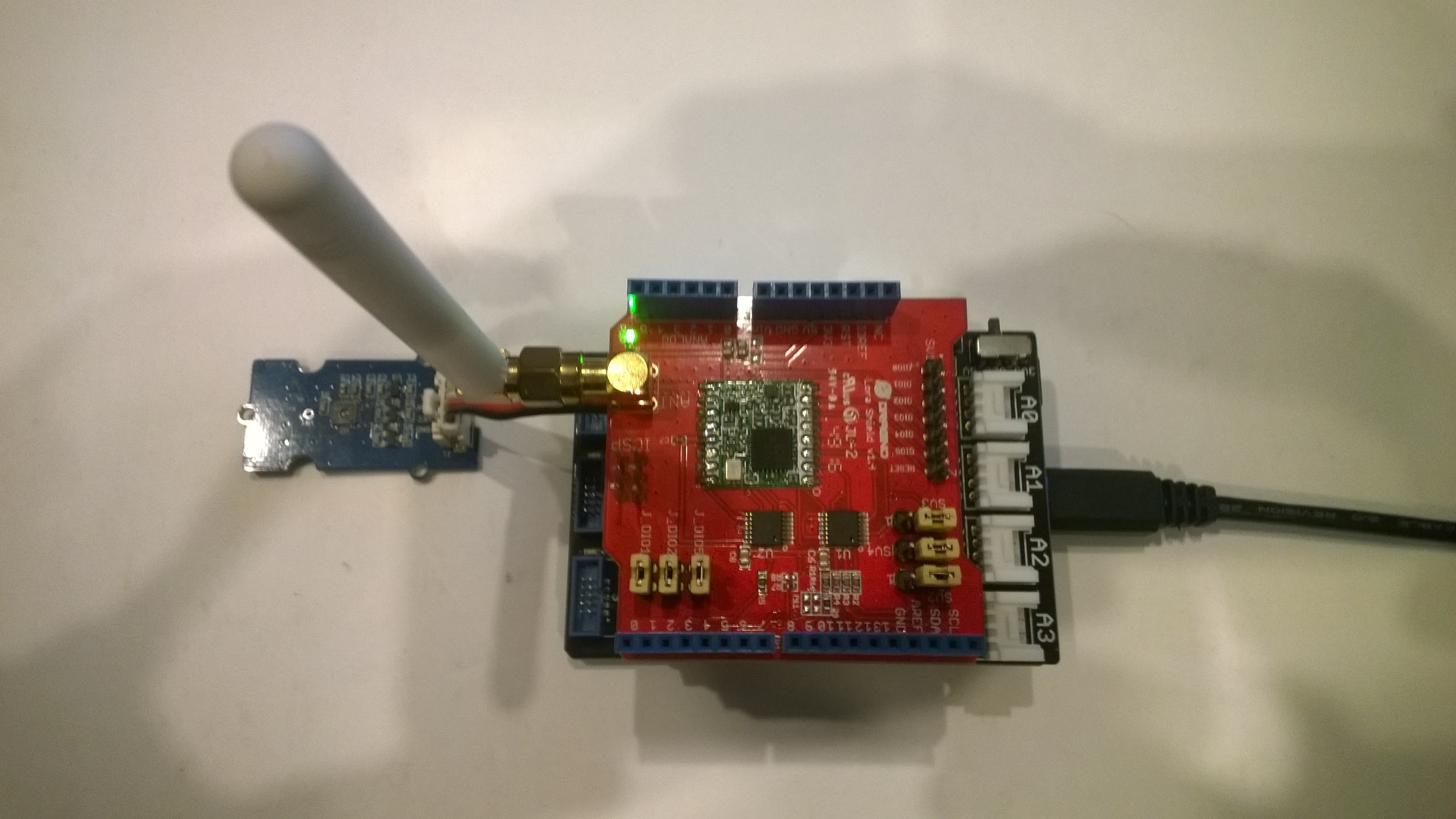
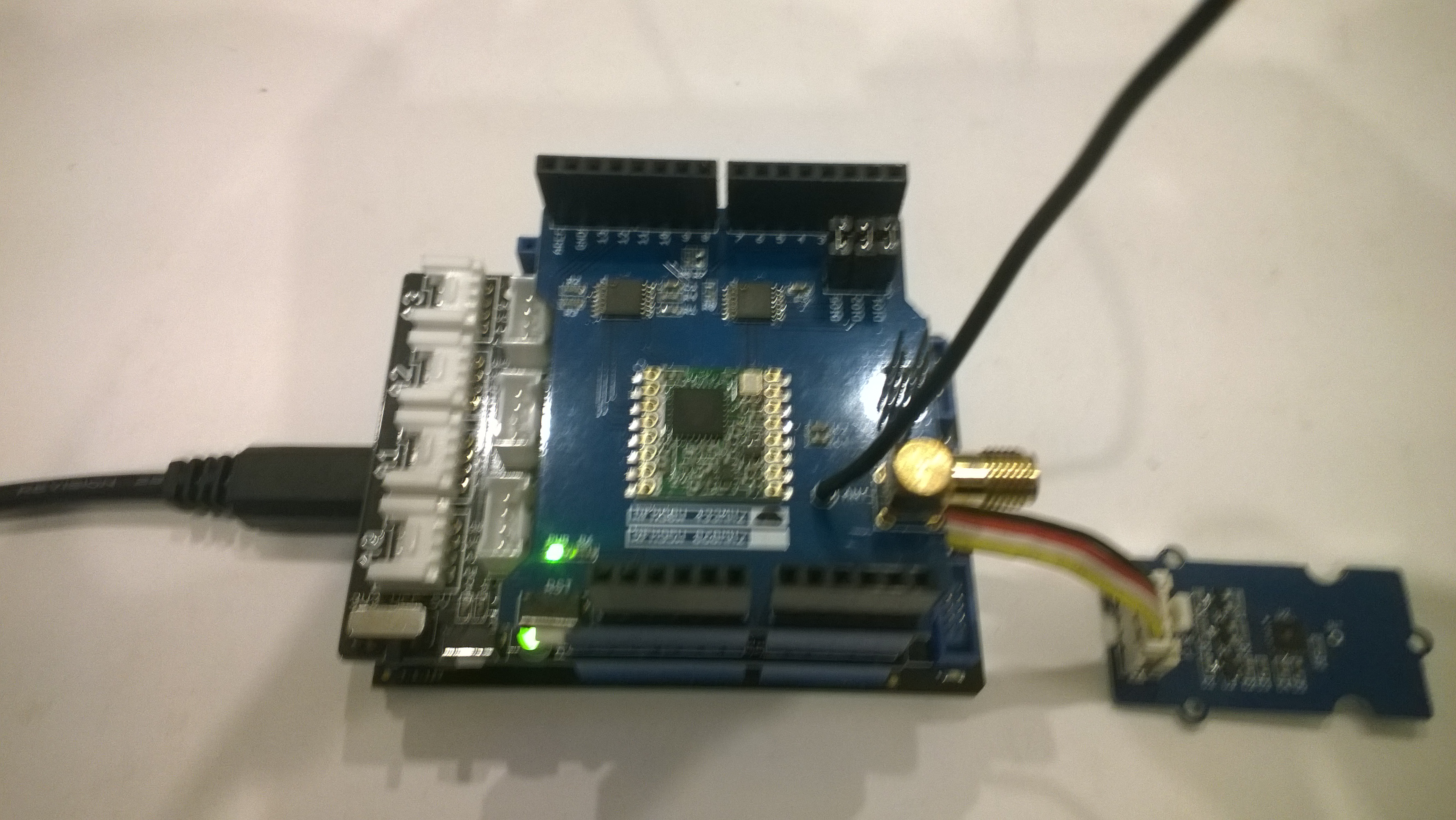
Elecrow shield
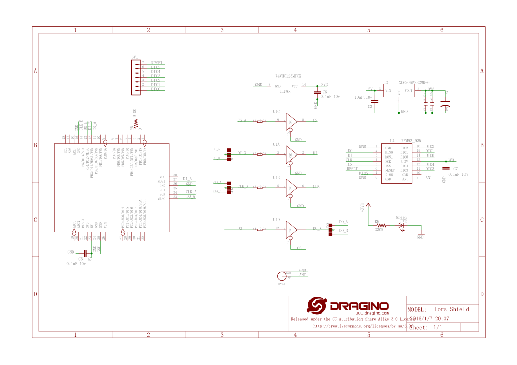
Dragino shield
MakerFabs shield
Net Micro Framework debug output from device
The thread '' (0x2) has exited with code 0 (0x0).
12:00:18 H:96.9 T:19.6
Transmit-Done
12:05:17 H:95.1 T:20.1
Transmit-Done
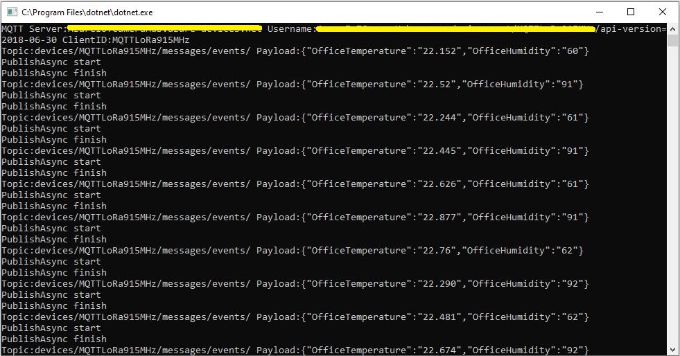
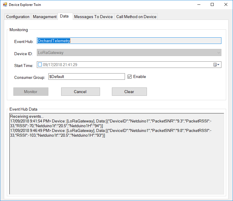
.Net Framework debug output Field Gateway
The thread 0x1550 has exited with code 0 (0x0).
21:21:49-RX From Netduino1 PacketSnr 9.5 Packet RSSI -40dBm RSSI -107dBm = 11 byte message "t 19.6,H 97"
 Sensor Netduino1t Value 19.6
 Sensor Netduino1H Value 97
 AzureIoTHubClient SendEventAsync start
 AzureIoTHubClient SendEventAsync finish
...
21:26:49-RX From Netduino1 PacketSnr 9.5 Packet RSSI -33dBm RSSI -103dBm = 11 byte message "t 20.1,H 95"
 Sensor Netduino1t Value 20.1
 Sensor Netduino1H Value 95
 AzureIoTHubClient SendEventAsync start
 AzureIoTHubClient SendEventAsync finish
The thread 0xfbc has exited with code 0 (0x0).
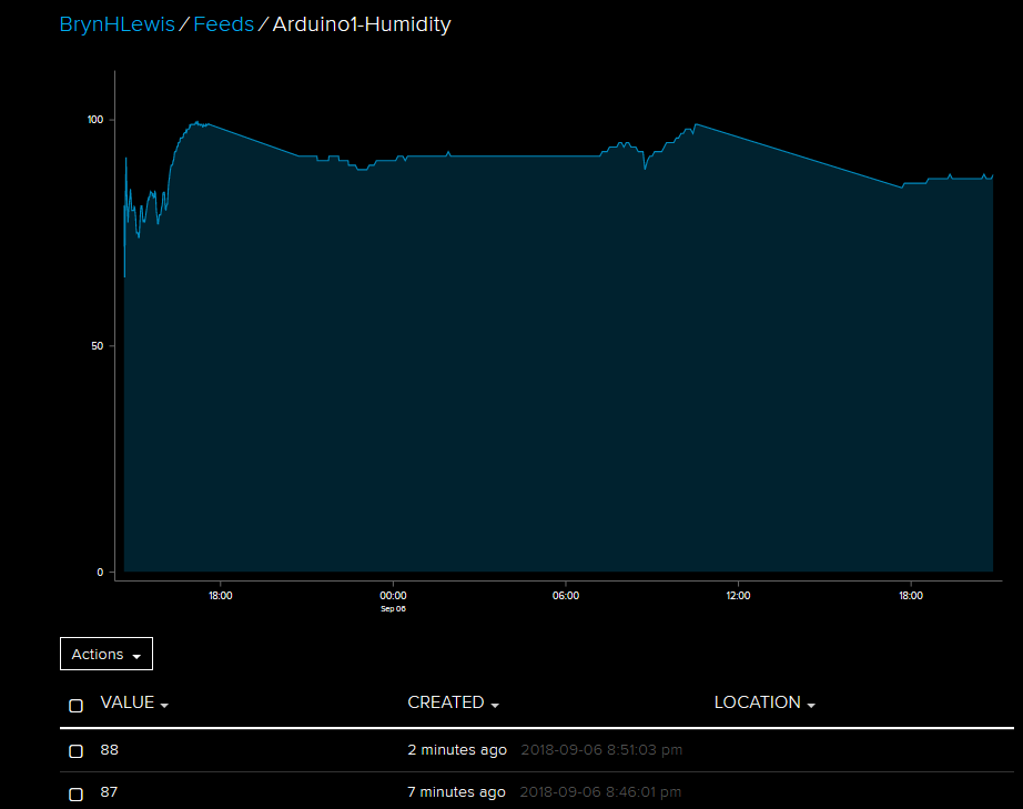
So far battery life and wireless communications range for the Arduino clients is looking pretty good. CRC presence checking and validation is turned so have a look at one of the sample clients.
It took a bit longer than expected as upgrading to the latest version (v1.18.0 as at 12 Sep 2018) of Microsoft.Azure.Devices.Client (from 1.6.3) broke my field gateway with timeouts and exceptions.
I’ll be doing some more testing over the next couple of weeks so it is a work in progress.
While building this AdaFruit.IO LoRa field gateway, and sample clients I revisited my RFM9XLoRa-Net library a couple of times adding functionality and renaming constants to make it more consistent. I made many of the default values public so they could be used in the field gateway config file.
The bare minimum configuration is
I have extended the NetMFsample application and library to show how the conditional compilation directive ADDRESSED_MESSAGES_PAYLOAD controls the configuration.
When the application is started the RFM9X is in sleep mode, then when the Receive method is called the device is set to ReceiveContinuous.
//---------------------------------------------------------------------------------
// Copyright (c) August 2018, devMobile Software
//
// Licensed under the Apache License, Version 2.0 (the "License");
// you may not use this file except in compliance with the License.
// You may obtain a copy of the License at
//
//     http://www.apache.org/licenses/LICENSE-2.0
//
// Unless required by applicable law or agreed to in writing, software
// distributed under the License is distributed on an "AS IS" BASIS,
// WITHOUT WARRANTIES OR CONDITIONS OF ANY KIND, either express or implied.
// See the License for the specific language governing permissions and
// limitations under the License.
//
//---------------------------------------------------------------------------------
namespace devMobile.IoT.NetMF.Rfm9X.Client
{
   using System;
   using System.Text;
   using System.Threading;
   using devMobile.IoT.NetMF.ISM;
   using Microsoft.SPOT;
   using SecretLabs.NETMF.Hardware.Netduino;

   public class Program
   {
      public static void Main()
      {
         Rfm9XDevice rfm9XDevice = new Rfm9XDevice(Pins.GPIO_PIN_D10, Pins.GPIO_PIN_D9, Pins.GPIO_PIN_D2);
         byte MessageCount = Byte.MinValue;

         rfm9XDevice.Initialise( frequency:915000000, paBoost: true, rxPayloadCrcOn: true);
#if ADDRESSED_MESSAGES
         rfm9XDevice.Receive(Encoding.UTF8.GetBytes("Netduino"));
#else
         rfm9XDevice.Receive();
#endif
         rfm9XDevice.OnDataReceived += rfm9XDevice_OnDataReceived;
         rfm9XDevice.OnTransmit += rfm9XDevice_OnTransmit;

         while (true)
         {
            string messageText = "Hello NetMF LoRa! " + MessageCount.ToString();
            MessageCount += 1;
            byte[] messageBytes = UTF8Encoding.UTF8.GetBytes(messageText);
            Debug.Print("Sending " + messageBytes.Length + " bytes message " + messageText);

#if ADDRESSED_MESSAGES
            rfm9XDevice.Send(UTF8Encoding.UTF8.GetBytes("LoRaIoT1"), messageBytes);
#else
            rfm9XDevice.Send(messageBytes);
#endif
            Thread.Sleep(10000);
         }
      }

      static void rfm9XDevice_OnTransmit()
      {
         Debug.Print("Transmit-Done");
      }

#if ADDRESSED_MESSAGES
      static void rfm9XDevice_OnDataReceived(byte[] address, float packetSnr, int packetRssi, int rssi, byte[] data)
#else
      static void rfm9XDevice_OnDataReceived(float packetSnr, int packetRssi, int rssi,  byte[] data)
#endif
      {
         try
         {
            string messageText = new string(UTF8Encoding.UTF8.GetChars(data));
#if ADDRESSED_MESSAGES
            string addressText = new string(UTF8Encoding.UTF8.GetChars(address));

            Debug.Print(DateTime.UtcNow.ToString("HH:MM:ss") + "-From " + addressText + " PacketSnr " + packetSnr.ToString("F1") + " Packet RSSI " + packetRssi + "dBm RSSI " + rssi + "dBm = " + data.Length + " byte message " + @"""" + messageText + @"""") ;
#else
            Debug.Print(DateTime.UtcNow.ToString("HH:MM:ss") + "-Rfm9X PacketSnr " + packetSnr.ToString("F1") + " Packet RSSI " + packetRssi + "dBm RSSI " + rssi + "dBm = " + data.Length + " byte message " + @"""" + messageText + @"""") ;
#endif
         }
         catch (Exception ex)
         {
            Debug.Print(ex.Message);
         }
      }
   }
}

namespace System.Diagnostics
{
   public enum DebuggerBrowsableState
   {
      Never = 0,
      Collapsed = 2,
      RootHidden = 3
   }
}
The reason for RFM9XLoRaNet was so that I could build a field gateway to upload telemetry data from “cheap n cheerful” *duino devices to Azure IoT Hubs and AdaFruit.IO.
I have extended the Windows10IoTCore sample application and library to show how the conditional compilation directive ADDRESSED_MESSAGES_PAYLOAD controls the configuration.
When the application is started the RFM9X is in sleep mode, then when the Receive method is called the device is set to ReceiveContinuous.
On receipt of a message, the message is parsed and the to/from addresses and payload extracted (ADDRESSED_MESSAGES defined) or passed to the client application for processing.