After debugging Windows 10 IoT Core, .NetMF and Wilderness Labs Meadow nRF24L01P libraries I figured yet another port, this time to a GHI Electronics Tiny CLR V2 powered device shouldn’t be “rocket science”.
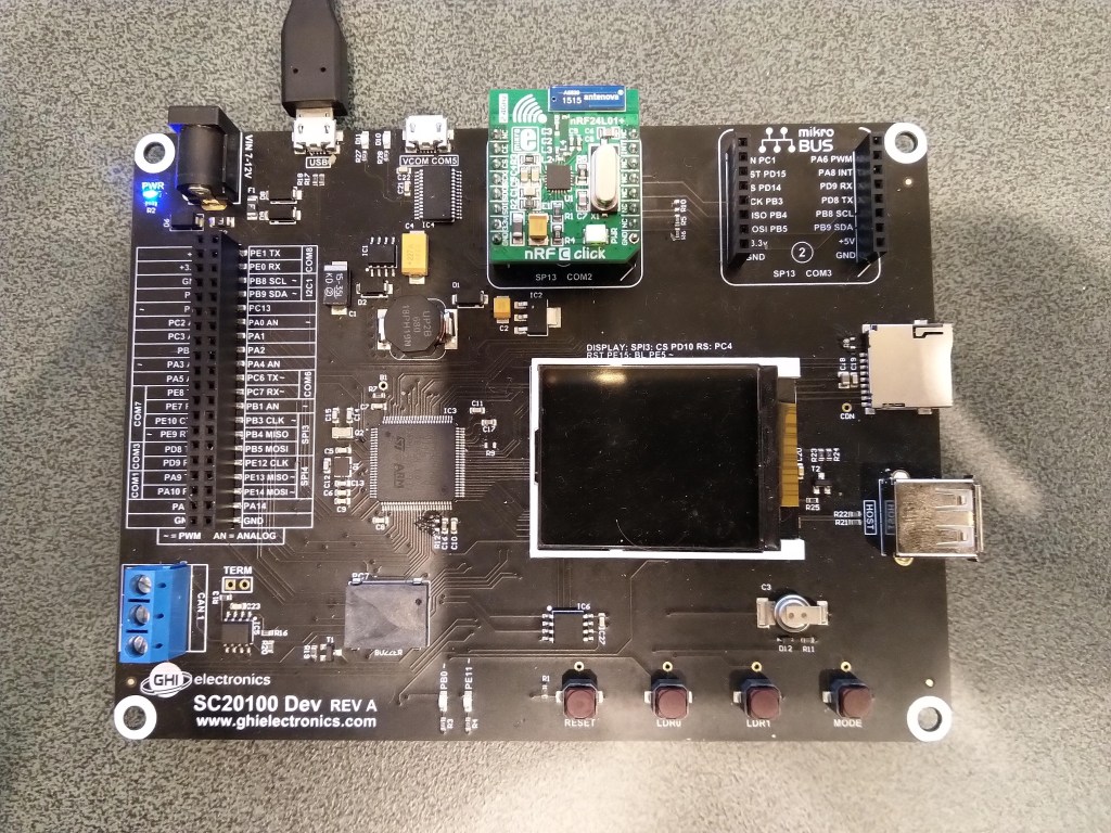
This test rig uses SC20100S Dev and MikroE nRF C Click boards.
//---------------------------------------------------------------------------------
// Copyright (c) May 2020, devMobile Software
//
// Licensed under the Apache License, Version 2.0 (the "License");
// you may not use this file except in compliance with the License.
// You may obtain a copy of the License at
//
//     http://www.apache.org/licenses/LICENSE-2.0
//
// Unless required by applicable law or agreed to in writing, software
// distributed under the License is distributed on an "AS IS" BASIS,
// WITHOUT WARRANTIES OR CONDITIONS OF ANY KIND, either express or implied.
// See the License for the specific language governing permissions and
// limitations under the License.
//
//---------------------------------------------------------------------------------
namespace devMobile.IoT.nRf24L01.ModuleSPI
{
   using System;
   using System.Diagnostics;
   using System.Reflection;
   using System.Text;
   using System.Threading;

   using GHIElectronics.TinyCLR.Devices.Gpio;
   using GHIElectronics.TinyCLR.Devices.Spi;
   using GHIElectronics.TinyCLR.Pins;

   class Program
   {
      const byte SETUP_AW = 0x03;
      const byte RF_CH = 0x05;
      const byte RX_ADDR_P0 = 0x0A;
      const byte R_REGISTER = 0b00000000;
      const byte W_REGISTER = 0b00100000;
      const string P0_Address = "ZYXWV";
      static SpiDevice nrf24L01Device;

      static void Main()
      {
         try
         {
            GpioController gpioController = GpioController.GetDefault();

            var settings = new SpiConnectionSettings()
            {
               ChipSelectType = SpiChipSelectType.Gpio,
               //ChipSelectLine = FEZ.GpioPin.D10,
               ChipSelectLine = gpioController.OpenPin(SC20100.GpioPin.PD3),
               Mode = SpiMode.Mode0,
               //Mode = SpiMode.Mode1,
               //Mode = SpiMode.Mode2,
               //Mode = SpiMode.Mode3,
               ClockFrequency = 500000,
               //ChipSelectActiveState = true
               ChipSelectActiveState = false,
               //ChipSelectHoldTime = new TimeSpan(0, 0, 0, 0, 500),
               //ChipSelectSetupTime = new TimeSpan(0, 0, 0, 0, 500),
            };

            var spiController = SpiController.FromName(SC20100.SpiBus.Spi3);

            Debug.WriteLine("nrf24L01Device Device...");
            nrf24L01Device = spiController.GetDevice(settings);
            if (nrf24L01Device == null)
            {
               Debug.WriteLine("nrf24L01Device == null");
            }

            Thread.Sleep(100);

            Debug.WriteLine("ConfigureSpiPort Done...");
            Debug.WriteLine("");

            Thread.Sleep(500);
         }
         catch (Exception ex)
         {
            Debug.WriteLine("Configure SpiPort " + ex.Message);
         }

         try
         {
            // Read the Address width
            Debug.WriteLine("Read address width");
            byte[] txBuffer1 = new byte[] { SETUP_AW | R_REGISTER, 0x0 };
            byte[] rxBuffer1 = new byte[txBuffer1.Length];

            Debug.WriteLine(" nrf24L01Device.TransferFullDuplex...SETUP_AW");
            Debug.WriteLine(" txBuffer:" + BitConverter.ToString(txBuffer1));
            nrf24L01Device.TransferFullDuplex(txBuffer1, rxBuffer1);
            Debug.WriteLine(" rxBuffer:" + BitConverter.ToString(rxBuffer1));

            // Extract then adjust the address width
            byte addressWidthValue = rxBuffer1[1];
            addressWidthValue &= 0b00000011;
            addressWidthValue += 2;
            Debug.WriteLine($"Address width 0x{SETUP_AW:x2} - Value 0X{rxBuffer1[1]:x2} Value adjusted {addressWidthValue}");
            Debug.WriteLine("");

            // Write Pipe0 Receive address
            Debug.WriteLine($"Write Pipe0 Receive Address {P0_Address}");
            byte[] txBuffer2 = new byte[addressWidthValue + 1];
            txBuffer2[0] = RX_ADDR_P0 | W_REGISTER;
            Array.Copy(Encoding.UTF8.GetBytes(P0_Address), 0, txBuffer2, 1, addressWidthValue);

            Debug.WriteLine(" nrf24L01Device.Write...RX_ADDR_P0");
            Debug.WriteLine(" txBuffer:" + BitConverter.ToString(txBuffer2));
            nrf24L01Device.Write(txBuffer2);
            Debug.WriteLine("");

            // Read Pipe0 Receive address
            Debug.WriteLine("Read Pipe0 Receive address");
            byte[] txBuffer3 = new byte[addressWidthValue + 1];
            txBuffer3[0] = RX_ADDR_P0 | R_REGISTER;
            byte[] rxBuffer3 = new byte[txBuffer3.Length];

            Debug.WriteLine(" nrf24L01Device.TransferFullDuplex...RX_ADDR_P0");
            Debug.WriteLine(" txBuffer:" + BitConverter.ToString(txBuffer3));
            nrf24L01Device.TransferFullDuplex(txBuffer3, rxBuffer3);
            Debug.WriteLine(" rxBuffer:" + BitConverter.ToString(rxBuffer3));
            Debug.WriteLine($"Address 0x{RX_ADDR_P0:x2} Address {UTF8Encoding.UTF8.GetString(rxBuffer3, 1, addressWidthValue)}");
            Debug.WriteLine("");

            // Read the RF Channel
            Debug.WriteLine("RF Channel read 1");
            byte[] txBuffer4 = new byte[] { RF_CH | R_REGISTER, 0x0 };
            byte[] rxBuffer4 = new byte[txBuffer4.Length];

            Debug.WriteLine(" nrf24L01Device.TransferFullDuplex...RF_CH");
            Debug.WriteLine(" txBuffer:" + BitConverter.ToString(txBuffer4));
            nrf24L01Device.TransferFullDuplex(txBuffer4, rxBuffer4);
            Debug.WriteLine(" rxBuffer:" + BitConverter.ToString(rxBuffer4));

            ushort rfChannel1 = rxBuffer4[1];
            rfChannel1 += 2400;
            Debug.WriteLine($"RF Channel 1 0x{RF_CH:x2} - Value 0X{rxBuffer4[1]:x2} - Value adjusted {rfChannel1}");
            Debug.WriteLine("");

            // Write the RF Channel
            Debug.WriteLine("RF Channel write");
            byte[] txBuffer5 = new byte[] { RF_CH | W_REGISTER, rxBuffer4[1]+=1};

            Debug.WriteLine(" nrf24L01Device.Write...RF_CH");
            Debug.WriteLine(" txBuffer:" + BitConverter.ToString(txBuffer5));
            nrf24L01Device.Write(txBuffer5);
            Debug.WriteLine("");

            // Read the RF Channel
            Debug.WriteLine("RF Channel read 2");
            byte[] txBuffer6 = new byte[] { RF_CH | R_REGISTER, 0x0 };
            byte[] rxBuffer6 = new byte[txBuffer6.Length];

            Debug.WriteLine(" nrf24L01Device.TransferFullDuplex...RF_CH");
            Debug.WriteLine(" txBuffer:" + BitConverter.ToString(txBuffer6));
            nrf24L01Device.TransferFullDuplex(txBuffer6, rxBuffer6);
            Debug.WriteLine(" rxBuffer:" + BitConverter.ToString(rxBuffer6));

            ushort rfChannel2 = rxBuffer6[1];
            rfChannel2 += 2400;
            Debug.WriteLine($"RF Channel 2 0x{RF_CH:x2} - Value 0X{rxBuffer6[1]:x2} - Value adjusted {rfChannel2}");
            Debug.WriteLine("");
         }
         catch (Exception ex)
         {
            Debug.WriteLine("Configure Port0 " + ex.Message);
         }
      }
   }
}
After lots of tinkering with SPI configuration options I can read and write my nRF24L01 device receive port address
The thread '<No Name>' (0x2) has exited with code 0 (0x0).
nrf24L01Device Device...
ConfigureSpiPort Done...

Read address width
 nrf24L01Device.TransferFullDuplex...SETUP_AW
 txBuffer:03-00
 rxBuffer:0E-03
Address width 0x03 - Value 0X03 Value adjusted 5

Write Pipe0 Receive Address ZYXWV
 nrf24L01Device.Write...RX_ADDR_P0
 txBuffer:2A-5A-59-58-57-56

Read Pipe0 Receive address
 nrf24L01Device.TransferFullDuplex...RX_ADDR_P0
 txBuffer:0A-00-00-00-00-00
 rxBuffer:0E-5A-59-58-57-56
Address 0x0a Address ZYXWV

RF Channel read 1
 nrf24L01Device.TransferFullDuplex...RF_CH
 txBuffer:05-00
 rxBuffer:0E-15
RF Channel 1 0x05 - Value 0X15 - Value adjusted 2421

RF Channel write
 nrf24L01Device.Write...RF_CH
 txBuffer:25-16

RF Channel read 2
 nrf24L01Device.TransferFullDuplex...RF_CH
 txBuffer:05-00
 rxBuffer:0E-16
RF Channel 2 0x05 - Value 0X16 - Value adjusted 2422

Pingback: TinyCLR OS V2 nRF24L01 library Part2 | devMobile's blog
Pingback: nanoFramework nRF24L01 library Part2 | devMobile's blog