Random wanderings through Microsoft Azure esp. PaaS plumbing, the IoT bits, AI on Micro controllers, AI on Edge Devices, .NET nanoFramework, .NET Core on *nix and ML.NET+ONNX
I have included sample application to show how to use the library
namespace devMobile.IoT.NetCore.GroveBaseHat
{
	using System;
	using System.Device.I2c;
	using System.Threading;

	class Program
	{
		static void Main(string[] args)
		{
			// bus id on the raspberry pi 3
			const int busId = 1;

			I2cConnectionSettings i2cConnectionSettings = new(busId, AnalogPorts.DefaultI2cAddress);

			using (I2cDevice i2cDevice = I2cDevice.Create(i2cConnectionSettings))
			using (AnalogPorts AnalogPorts = new AnalogPorts(i2cDevice))
			{
				Console.WriteLine($"{DateTime.Now:HH:mm:SS} Version:{AnalogPorts.Version()}");
				Console.WriteLine();

				double powerSupplyVoltage = AnalogPorts.PowerSupplyVoltage();
				Console.WriteLine($"{DateTime.Now:HH:mm:SS} Power Supply Voltage:{powerSupplyVoltage:F2}v");

				while (true)
				{
					double value = AnalogPorts.Read(AnalogPorts.AnalogPort.A0);
					double rawValue = AnalogPorts.ReadRaw(AnalogPorts.AnalogPort.A0);
					double voltageValue = AnalogPorts.ReadVoltage(AnalogPorts.AnalogPort.A0);

					Console.WriteLine($"{DateTime.Now:HH:mm:SS} Value:{value:F2} Raw:{rawValue:F2} Voltage:{voltageValue:F2}v");
					Console.WriteLine();

					Thread.Sleep(1000);
				}
			}
		}
	}
}
The GROVE_BASE_HAT_RPI and GROVE_BASE_HAT_RPI_ZERO are used to specify the number of available analog ports.
The next step was to figure out how to configure a Pulse Width Modulation (PWM) output and an Analog Input so I could adjust the duty cycle and control the brightness of a Light Emitting Diode(LED).
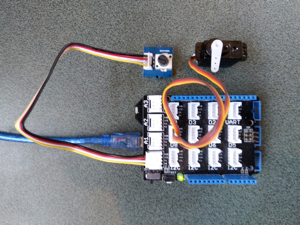
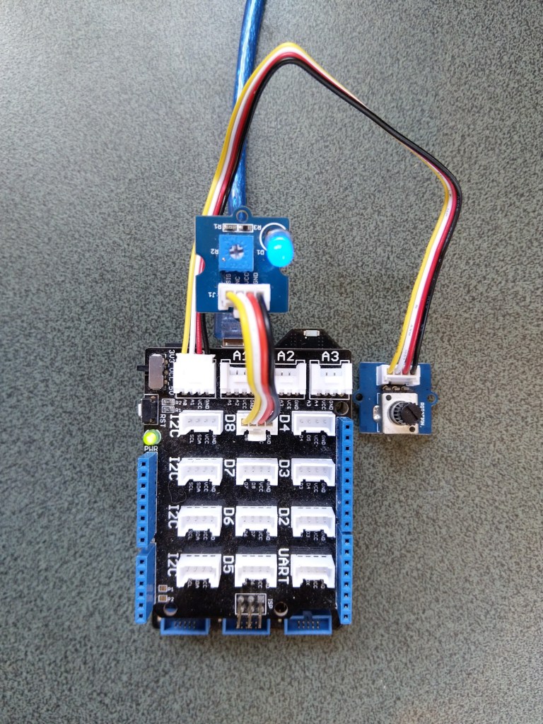
Netduino 3 ADC & PWN test rig
My test rig uses (prices as at Aug 2020) the following parts
 public class Program
   {
      public static void Main()
      {
         Debug.WriteLine("devMobile.Longboard.AdcTest starting");
         Debug.WriteLine(AdcController.GetDeviceSelector());

         try
         {
            AdcController adc = AdcController.GetDefault();
            AdcChannel adcChannel = adc.OpenChannel(0);

            while (true)
            {
               double value = adcChannel.ReadRatio();

               Debug.WriteLine($"Value: {value:F2}");

               Thread.Sleep(100);
            }
         }
         catch (Exception ex)
         {
            Debug.WriteLine(ex.Message);
         }
      }
   }
The nanoFramework code polls for the rotary angle sensor for its position value every 100mSec.
The setup to use for the Analog to Digital Convertor(ADC) port was determined by looking at the board.h and target_windows_devices_adc_config.cpp file.
//
// Copyright (c) 2018 The nanoFramework project contributors
// See LICENSE file in the project root for full license information.
//

#include <win_dev_adc_native_target.h>

const NF_PAL_ADC_PORT_PIN_CHANNEL AdcPortPinConfig[] = {

    // ADC1
    {1, GPIOC, 0, ADC_CHANNEL_IN10},
    {1, GPIOC, 1, ADC_CHANNEL_IN11},

    // ADC2
    {2, GPIOC, 2, ADC_CHANNEL_IN14},
    {2, GPIOC, 3, ADC_CHANNEL_IN15},

    // ADC3
    {3, GPIOC, 4, ADC_CHANNEL_IN12},
    {3, GPIOC, 5, ADC_CHANNEL_IN13},

    // these are the internal sources, available only at ADC1
    {1, NULL, 0, ADC_CHANNEL_SENSOR},
    {1, NULL, 0, ADC_CHANNEL_VREFINT},
    {1, NULL, 0, ADC_CHANNEL_VBAT},
};

const int AdcChannelCount = ARRAYSIZE(AdcPortPinConfig);
The call to AdcController.GetDeviceSelector() only returned one controller
The thread '<No Name>' (0x2) has exited with code 0 (0x0).
devMobile.Longboard.AdcTest starting
ADC1
After some experimentation it appears that only A0 & A1 work on a Netduino. (Aug 2020).
My PWM test harness
public class Program
{
   public static void Main()
   {
      Debug.WriteLine("devMobile.Longboard.PwmTest starting");
      Debug.WriteLine(PwmController.GetDeviceSelector());

      try
      {
         PwmController pwm = PwmController.FromId("TIM5");
         AdcController adc = AdcController.GetDefault();
         AdcChannel adcChannel = adc.OpenChannel(0);

         PwmPin pwmPin = pwm.OpenPin(PinNumber('A', 0));
         pwmPin.Controller.SetDesiredFrequency(1000);
         pwmPin.Start();

         while (true)
         {
            double value = adcChannel.ReadRatio();

            Debug.WriteLine(value.ToString("F2"));

            pwmPin.SetActiveDutyCyclePercentage(value);

            Thread.Sleep(100);
         }
      }
      catch (Exception ex)
      {
         Debug.WriteLine(ex.Message);
      }
   }

   private static int PinNumber(char port, byte pin)
   {
      if (port < 'A' || port > 'J')
         throw new ArgumentException();
      return ((port - 'A') * 16) + pin;
   }
}
I had to refer to the Netduino schematic to figure out pin mapping
With my test rig (with easy access to D0 thru D8) I found that only D2,D3,D7 and D8 work as PWM outputs.
I had previously have measured the AnalogInput read rate of my Netduino devices and was surprised by some of the numbers. Now, I have another project in the planning phase which will be using a GHI Electronics Fez Lemur or Fez Panda III device and had time for a quick test.
This is just a simple test, not terribly representative of real world just to get comparable numbers.
public static void Main()
{
   int value;
   AnalogInput x1 = new AnalogInput(FEZLemur.AnalogInput.A0);
   Stopwatch stopwatch = Stopwatch.StartNew();

   Debug.Print("Starting");

   stopwatch.Start();
   for (int i = 0; i < SampleCount; i++)
   {
      value = x1.ReadRaw();
   }
   stopwatch.Stop();

   Debug.Print("Duration = " + stopwatch.ElapsedMilliseconds.ToString() + " mSec " + (SampleCount * 1000 / stopwatch.ElapsedMilliseconds).ToString() + "/sec");
}