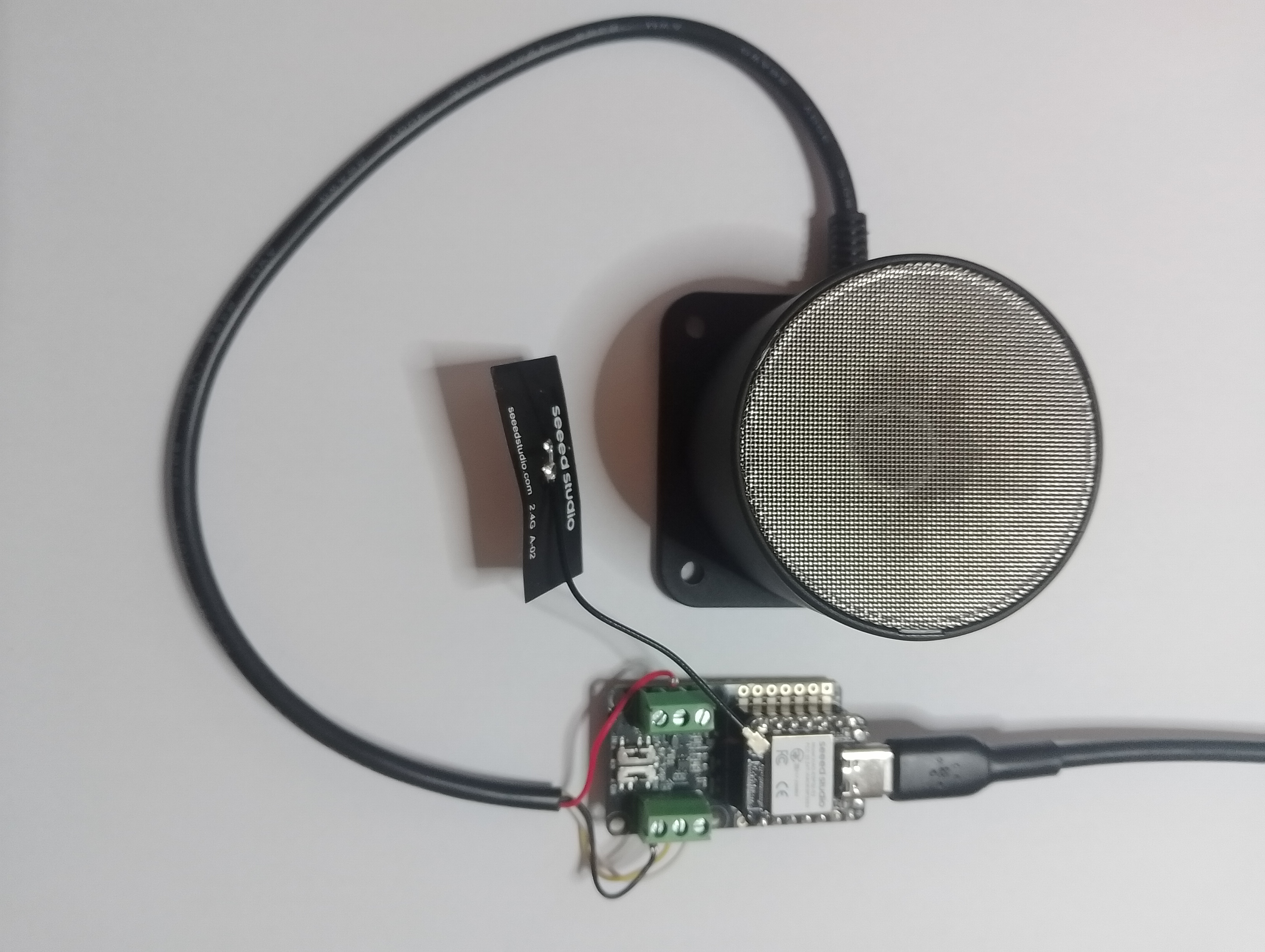
As part of this series of samples comparing Arduino to nanoFramework to .NET IoT Device “Proof of Concept (PoC) applications, several posts use a SenseCap Industrial Light Intensity Sensor (SKU314990739 or SKU 314990740)
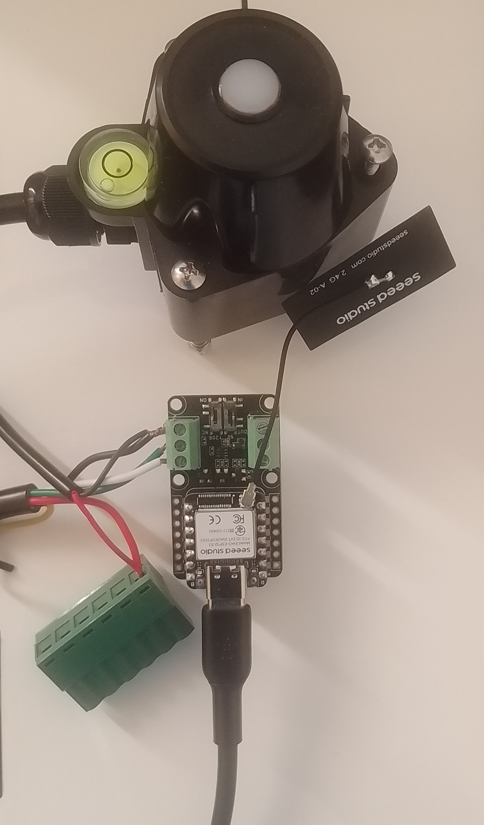
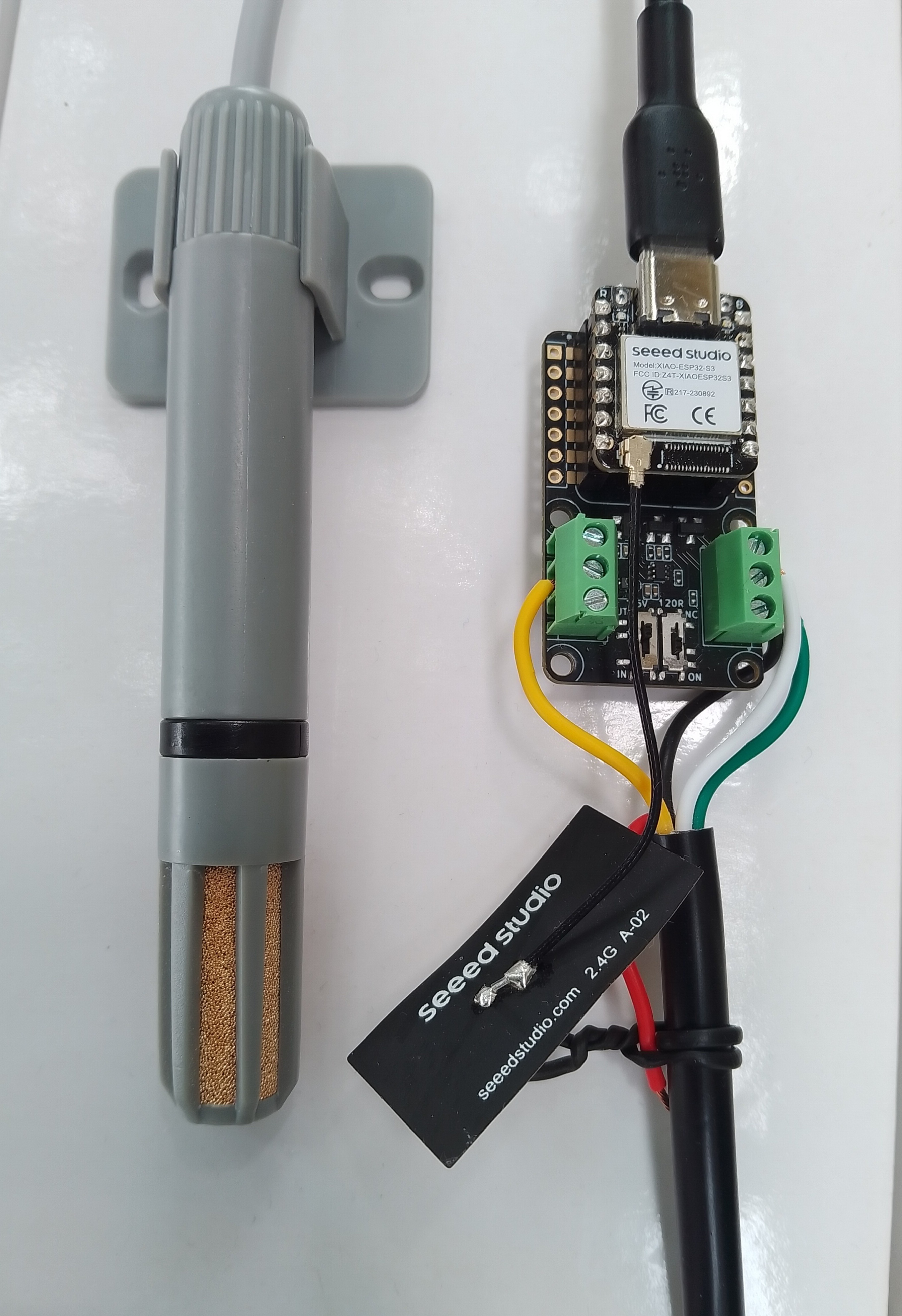
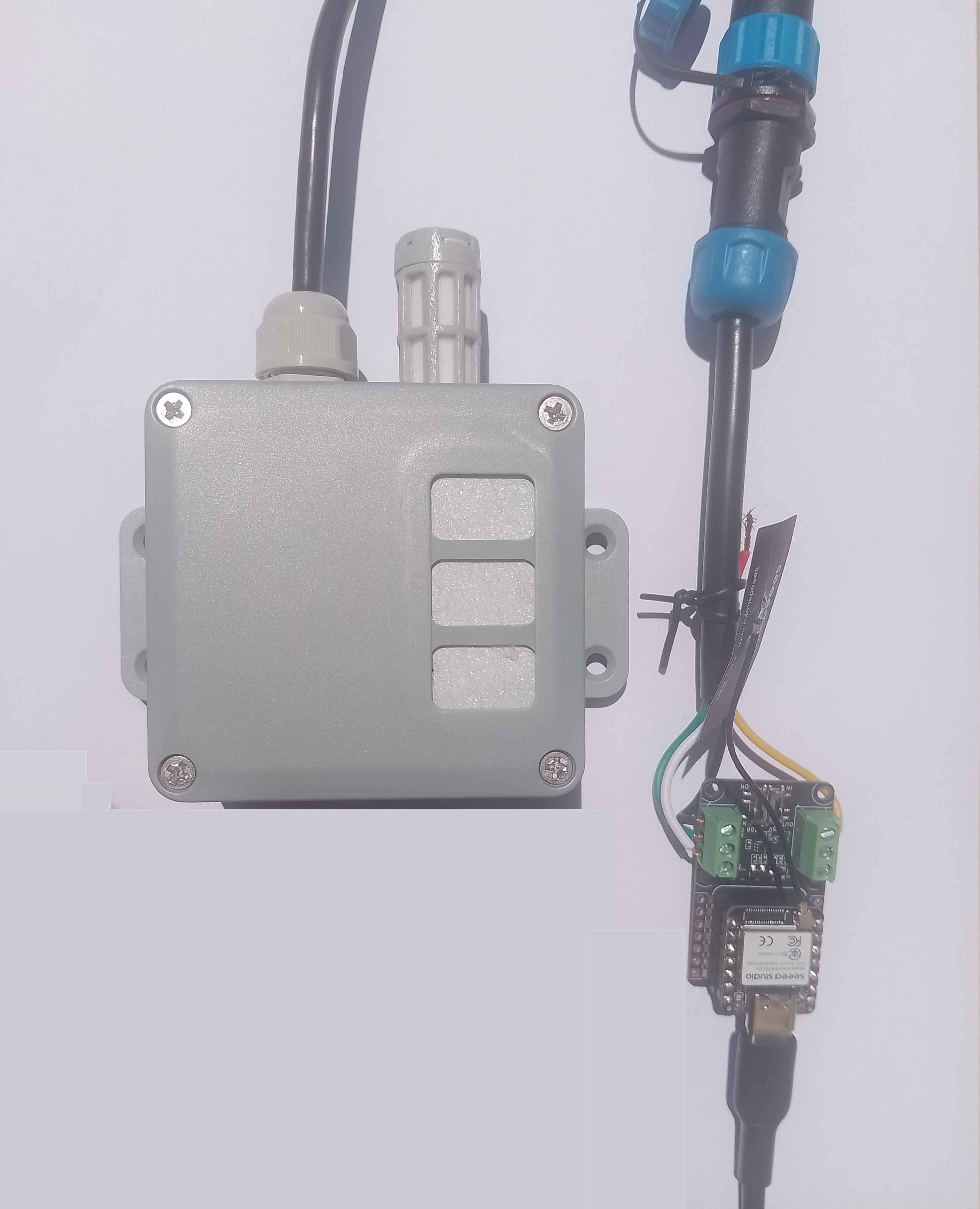
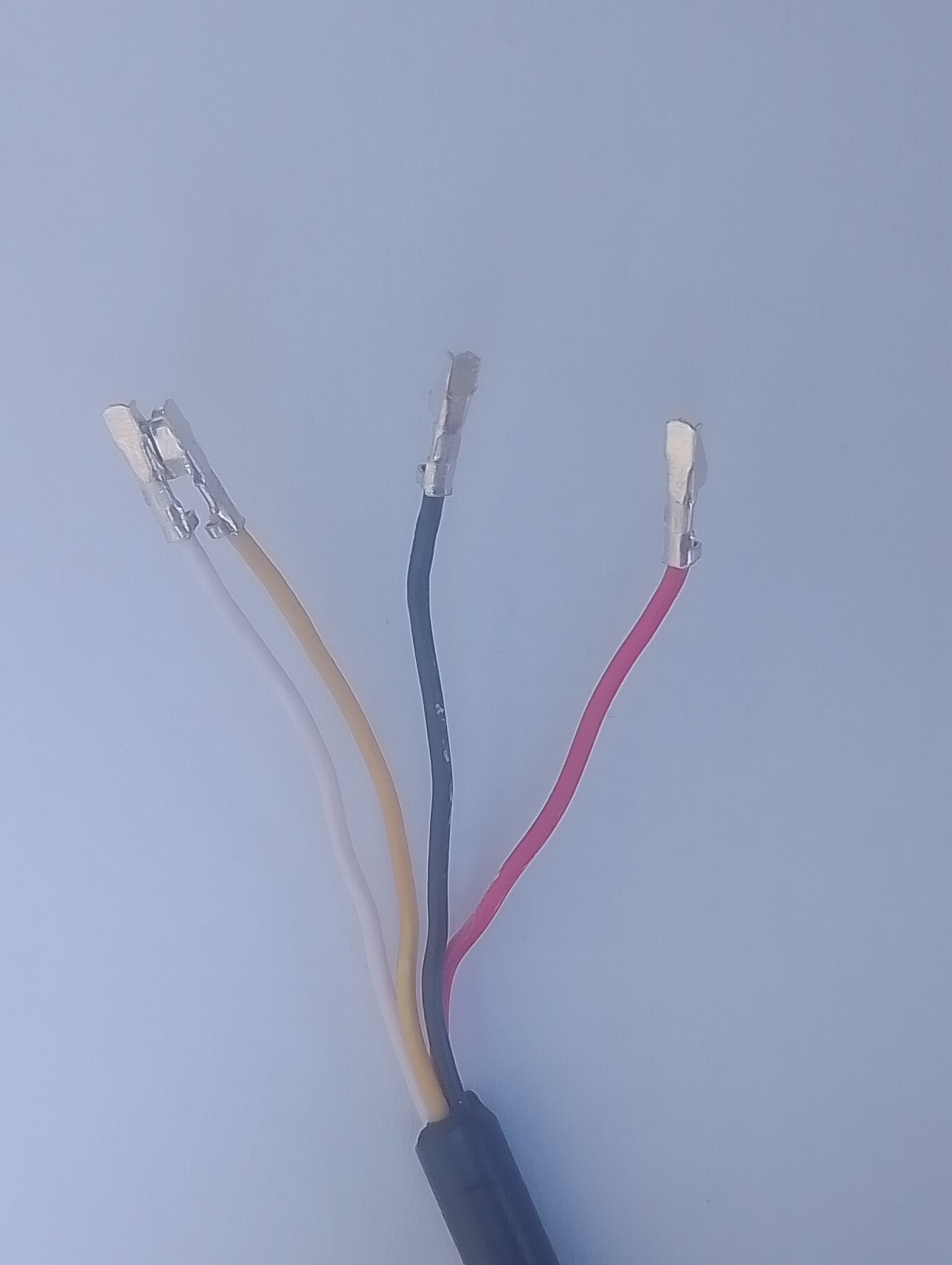
I cut one of the cables of a spare Industrial IP68 Modbus RS485 1-to-4 Splitter/Hub to connect the sensor to the RS485 breakout board. The sensor has an operating voltage of 3.6-30V but it is connected to the 12V supply pin. Initially, I had the sensor connected to the 5V output of the RS485 Breakout Board for Seeed Studio XIAO (SKU 113991354) so it didn’t work.
HardwareSerial RS485Serial(1);
ModbusMaster node;
// -----------------------------
// RS485 Pin Assignments (Corrected)
// -----------------------------
const int RS485_RX = 6; // UART1 RX
const int RS485_TX = 5; // UART1 TX
const int RS485_EN = D2;
// Sensor/Modbus parameters (from datasheet)
#define MODBUS_SLAVE_ID 0x0d
#define NUMBER_OF_REGISTERS_TO_READ 0x03
#define REG_LUX_HIGH 0x0000
#define REG_LUX_LOW 0x0001
#define REG_STATUS 0x0002
// Forward declarations for ModbusMaster callbacks
void preTransmission();
void postTransmission();
void setup() {
Serial.begin(9600);
delay(5000);
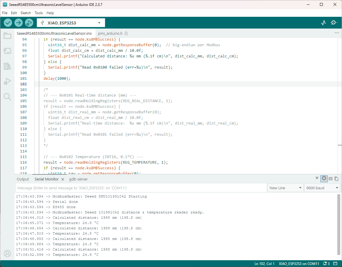
Serial.println("ModbusMaster: Seeed SKU 314990740 starting");
// Wait for the hardware serial to be ready
while (!Serial)
;
Serial.println("Serial done");
pinMode(RS485_EN, OUTPUT);
digitalWrite(RS485_EN, LOW); // Start in RX mode
// Datasheet: 9600 baud, 8N1
RS485Serial.begin(9600, SERIAL_8N1, RS485_RX, RS485_TX);
while (!RS485Serial)
;
Serial.println("RS485 done");
// Tie ModbusMaster to the UART we just configured
node.begin(MODBUS_SLAVE_ID, RS485Serial);
// Register callbacks for half-duplex direction control
node.preTransmission(preTransmission);
node.postTransmission(postTransmission);
}
// Toggle DE/RE around TX per ModbusMaster design
void preTransmission() {
digitalWrite(RS485_EN, HIGH); // enable driver (TX)
delayMicroseconds(250); // transceiver turn-around margin
}
void postTransmission() {
delayMicroseconds(250); // ensure last bit left the wire
digitalWrite(RS485_EN, LOW); // back to receive
}
void loop() {
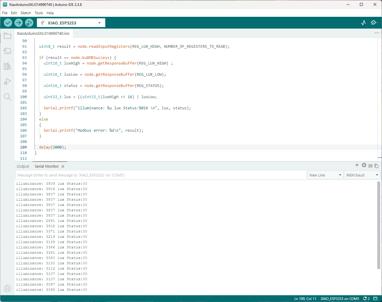
uint8_t result = node.readInputRegisters(REG_LUX_HIGH, NUMBER_OF_REGISTERS_TO_READ);
if (result == node.ku8MBSuccess) {
uint16_t luxHigh = node.getResponseBuffer(REG_LUX_HIGH) ;
uint16_t luxLow = node.getResponseBuffer(REG_LUX_LOW);
uint16_t status = node.getResponseBuffer(REG_STATUS);
uint32_t lux = ((uint32_t)luxHigh << 16) | luxLow;
Serial.printf("illuminance: %u lux Status:%02X \n", lux, status);
}
else
{
Serial.printf("Modbus error: %d\n", result);
}
delay(60000);
}
I do wonder how “accurately” the sensor has to be mounted because it has a level indicator and spring-loaded bolts.