Random wanderings through Microsoft Azure esp. PaaS plumbing, the IoT bits, AI on Micro controllers, AI on Edge Devices, .NET nanoFramework, .NET Core on *nix and ML.NET+ONNX
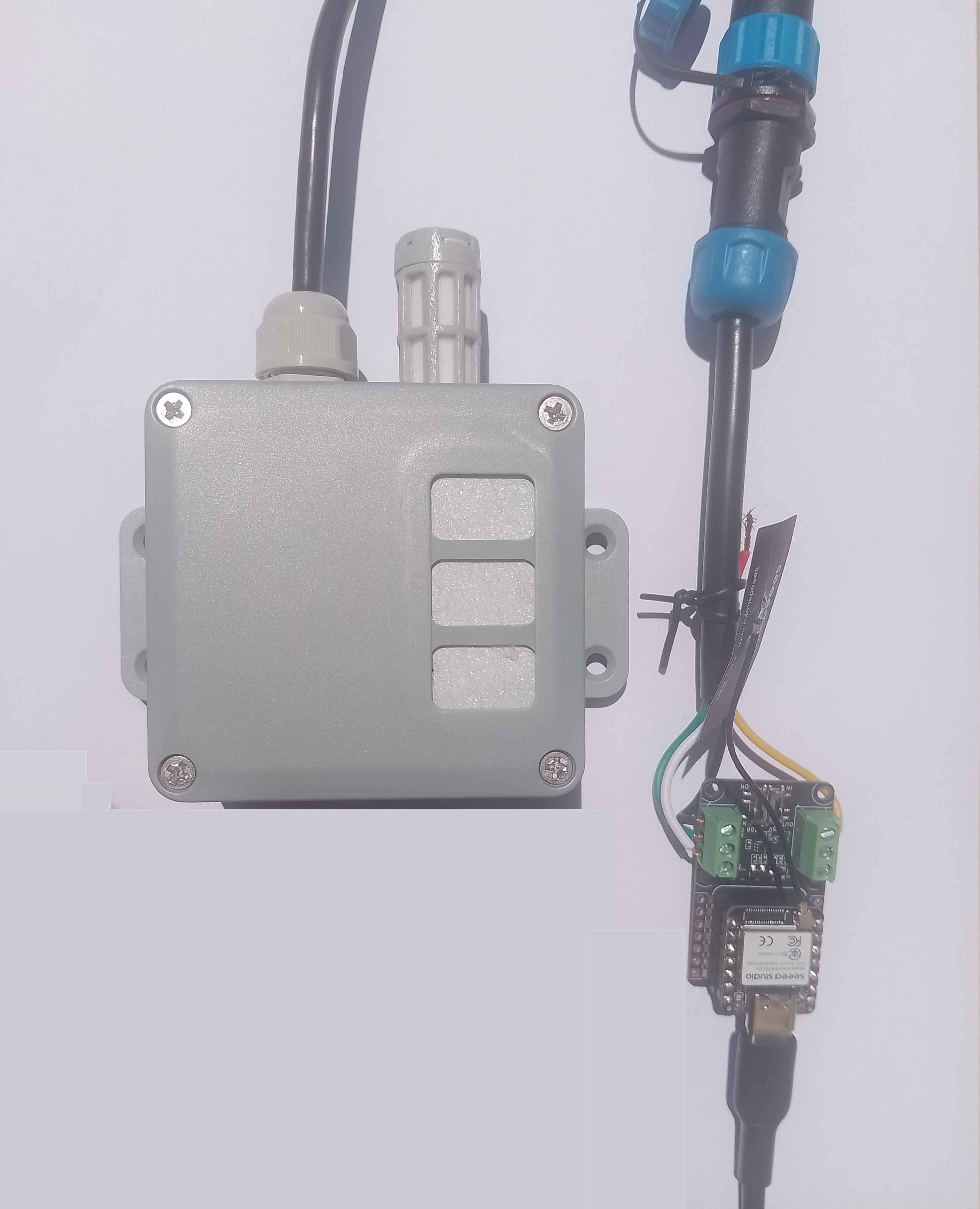
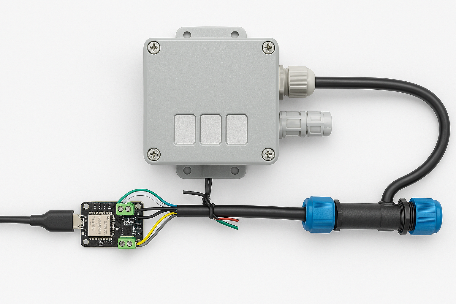
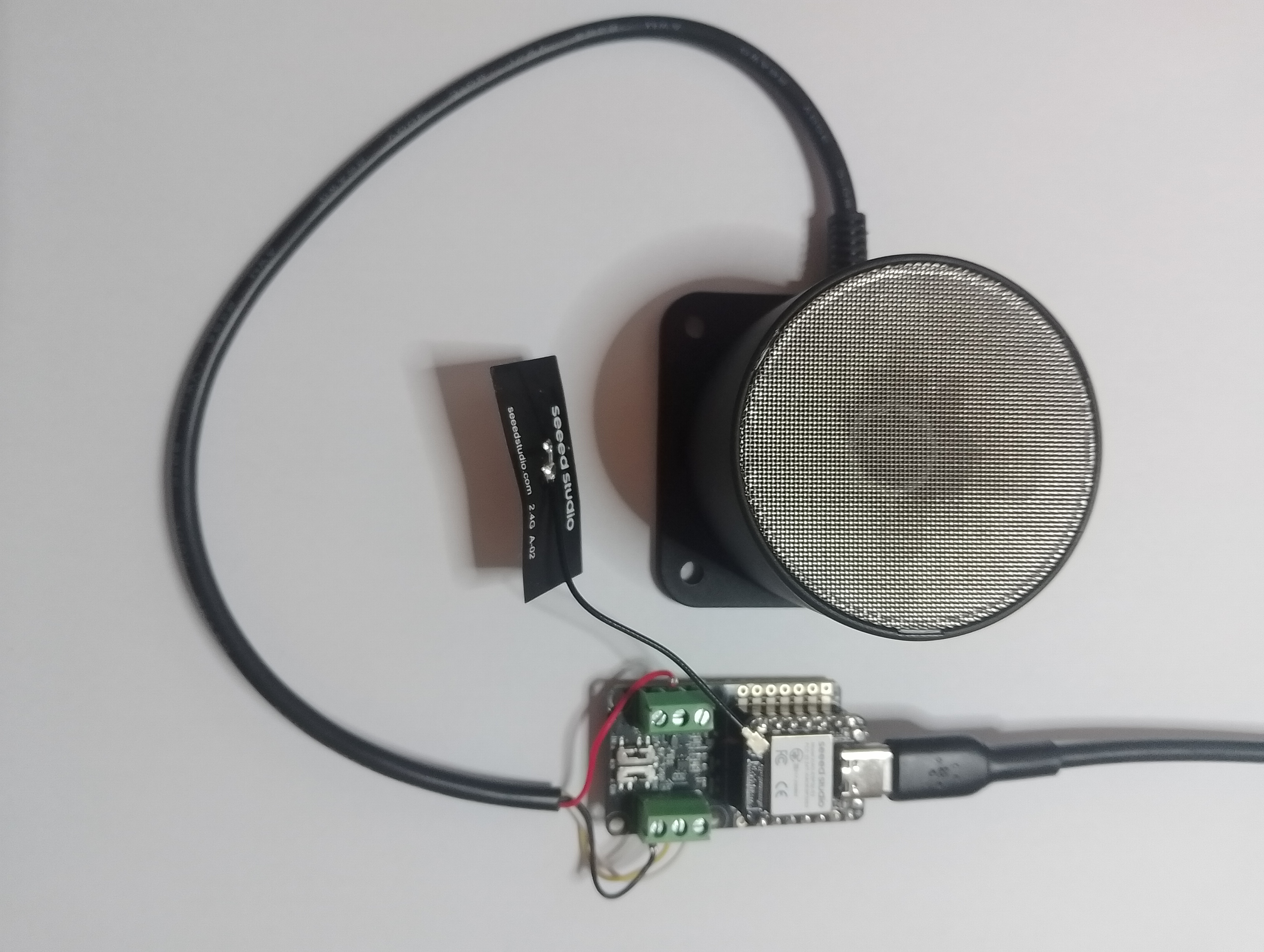
// XIAO ESP32S3 + RS485 breakout + Seeed 101991042 (RS-485 Modbus RTU)
// Reads: 0x0100 (calculated distance, mm), 0x0101 (real-time distance, mm),
// 0x0102 (temperature, 0.1°C). Can write 0x0200 (slave address).
// Serial: 9600 8N1 per datasheet. (Default slave addr = 0x01)
//Iot.Device.Modbus (namespace Iot.Device.Modbus.Client)
//using Iot.Device.Modbus;
using Iot.Device.Modbus.Client;
//using Microsoft.Extensions.Logging;
using nanoFramework.Hardware.Esp32;
//using nanoFramework.Logging.Debug;
using System;
using System.Diagnostics;
using System.IO.Ports;
using System.Threading;
namespace SeeedRS485500cmUltrasonicLevelSensor
{
public class Program
{
// === Sensor Modbus params (from Seeed datasheet) ===
private const byte SlaveAddress = 0x01; // default
private const ushort RegCalcDistance = 0x0100;// mm, ~500ms processing
//private const ushort RegRealDistance = 0x0101;// mm, ~100ms
private const ushort RegTemperature = 0x0102;// INT16, 0.1°C units
private const ushort RegSlaveAddress = 0x0200;// R/W address register
public static void Main()
{
ModbusClient _client;
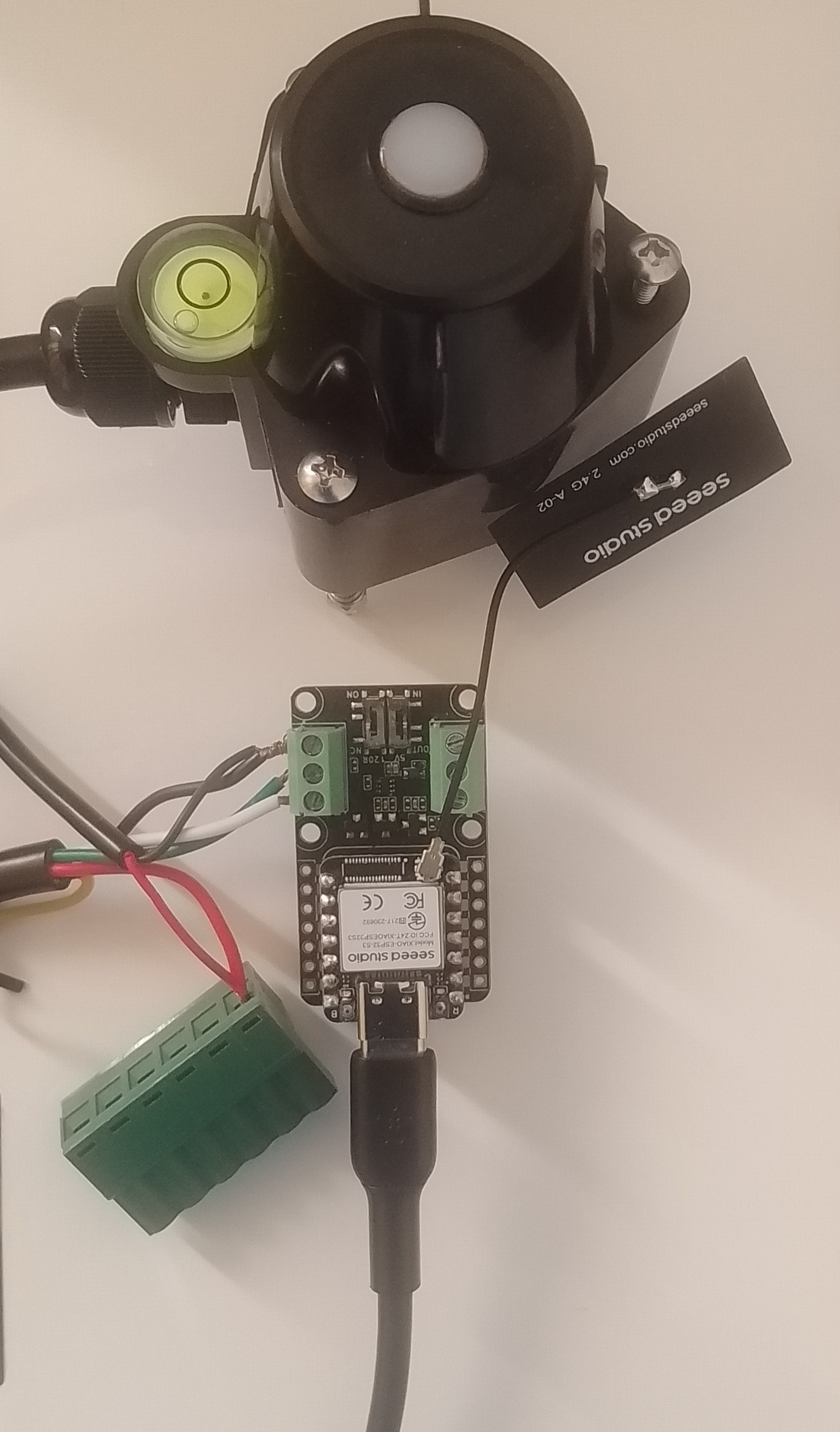
Console.WriteLine("Modbus: Seeed SKU101991042 Starting");
Configuration.SetPinFunction(Gpio.IO06, DeviceFunction.COM2_RX);
Configuration.SetPinFunction(Gpio.IO05, DeviceFunction.COM2_TX);
// This port number is a bit weird, need to double check in RS485 Sender/Receiver apps
Configuration.SetPinFunction(Gpio.IO03, DeviceFunction.COM2_RTS);
var ports = SerialPort.GetPortNames();
Debug.WriteLine("Available ports: ");
foreach (string port in ports)
{
Debug.WriteLine($" {port}");
}
using (_client = new ModbusClient("COM2"))
{
_client.ReadTimeout = _client.WriteTimeout = 2000;
//_client.Logger = new DebugLogger("ModbusClient")
//{
// MinLogLevel = LogLevel.Debug
//};
while (true)
{
try
{
// 0x0100 Calculated distance (mm). Takes ~500ms to compute per datasheet.
short[] calc = _client.ReadHoldingRegisters(SlaveAddress, RegCalcDistance, 1);
ushort calcMm = (ushort)calc[0];
float calcCm = calcMm / 10.0f;
Console.WriteLine($"Calculated distance: {calcMm} mm ({calcCm:F1} cm)");
/*
// 0x0101 Real-time distance (mm). Faster ~100ms response.
short[] real = _client.ReadHoldingRegisters(SlaveAddress, RegRealDistance, 1);
short realMm = real[0];
float realCm = realMm / 10.0f;
Console.WriteLine($"Real-time distance: {realMm} mm ({realCm:F1} cm)");
*/
// 0x0102 Temperature (INT16, 0.1°C)
short[] temp = _client.ReadHoldingRegisters(SlaveAddress, RegTemperature, 1);
short tempRaw = unchecked((short)temp[0]); // signed per datasheet
float tempC = tempRaw / 10.0f;
Console.WriteLine($"Temperature: {tempC:F1} °C");
}
catch (Exception ex)
{
Console.WriteLine($"Modbus read failed: {ex.Message}");
}
Thread.Sleep(10000);
}
}
}
}
}
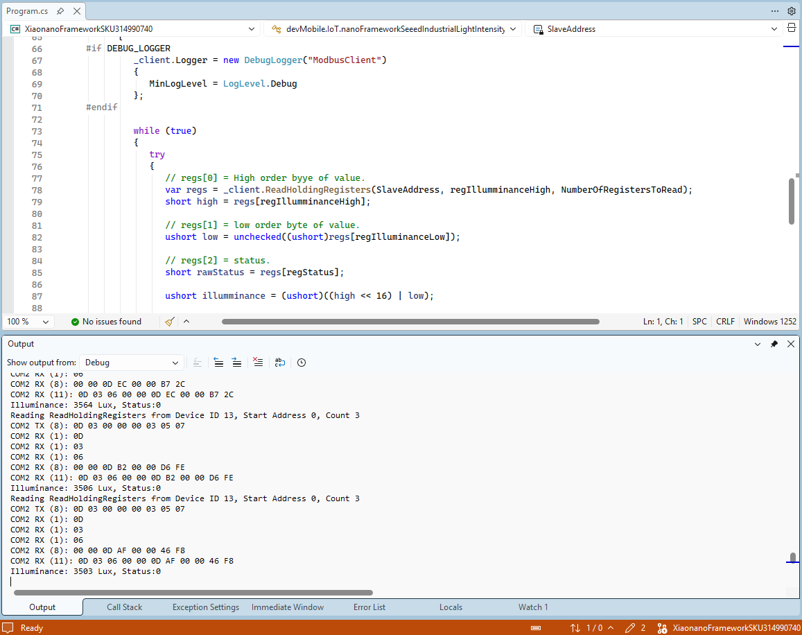
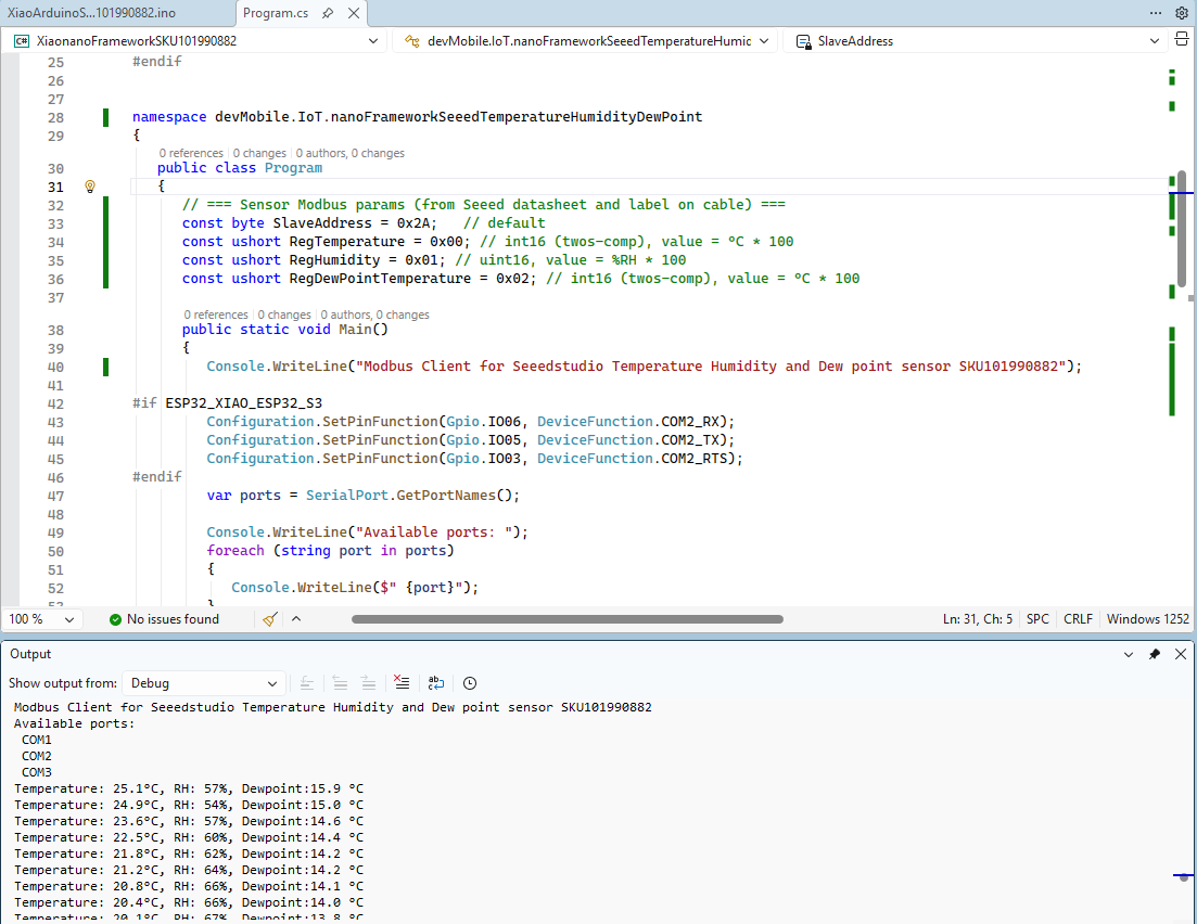
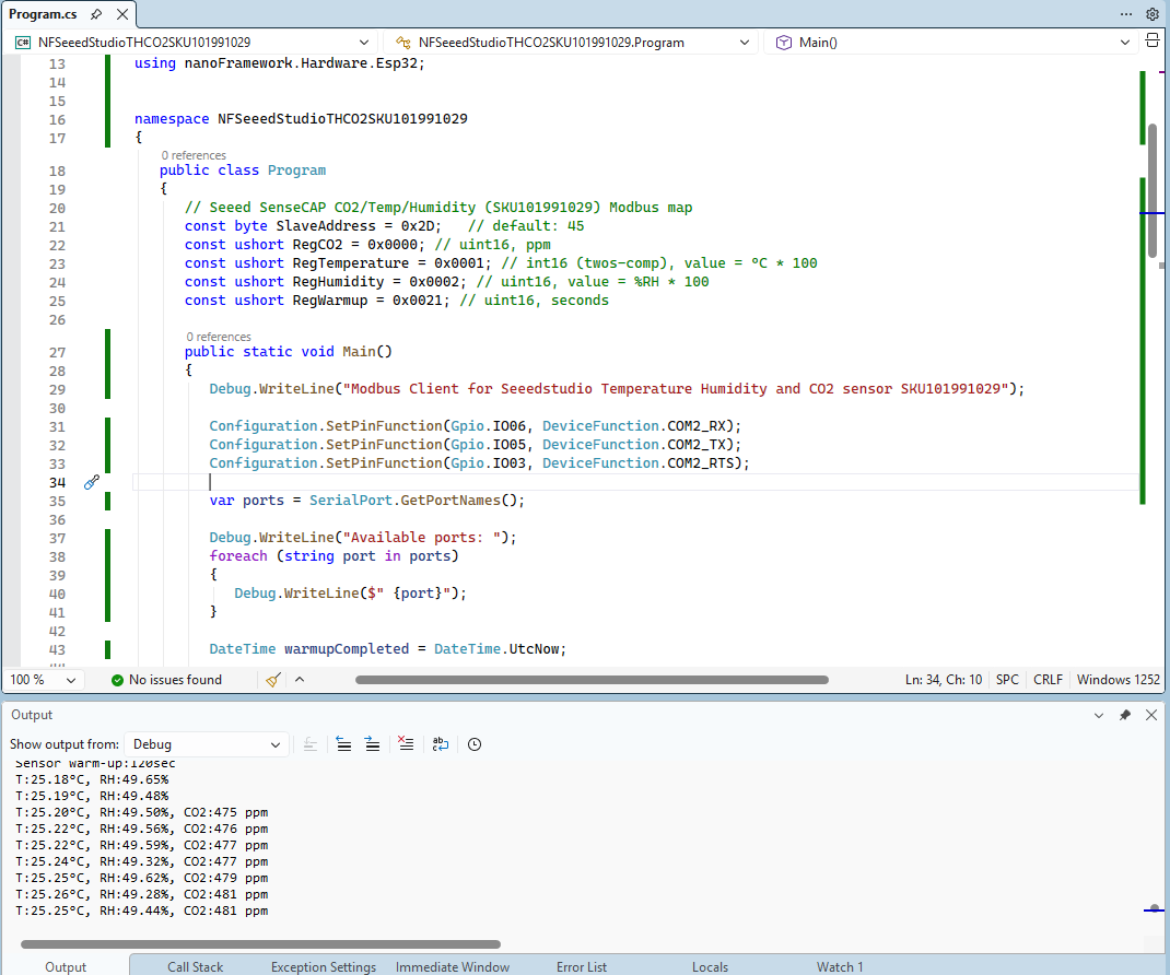
The nanoFramework logging support made debugging connectivity issues much faster. So much so I started with the nanoFramework application then progressed to the Arduino version.
I had to add a short delay between each Modbus sensor value read to stop timeout errors.
The PEM encoded root CA certificate chain that is used to validate the server
public const string CA_ROOT_PEM = @"-----BEGIN CERTIFICATE-----
CN: CN = Microsoft Azure ECC TLS Issuing CA 03
-----END CERTIFICATE-----
-----BEGIN CERTIFICATE-----
CN: CN = DigiCert Global Root G3
-----END CERTIFICATE-----";

The PEM encoded certificate chain that is used to authenticate the device
public const string CLIENT_CERT_PEM_A = @"-----BEGIN CERTIFICATE-----
-----BEGIN CERTIFICATE-----
 CN=Self signed device certificate
-----END CERTIFICATE-----
-----BEGIN CERTIFICATE-----
 CN=Self signed Intermediate certificate
-----END CERTIFICATE-----";

 The PEM encoded private key of device
public const string CLIENT_KEY_PEM_A = @"-----BEGIN EC PRIVATE KEY-----
-----END EC PRIVATE KEY-----";
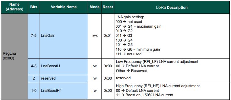
Every so often I print my code out (landscape for notes in margin, double sided to save paper, and colour so it looks like Visual Studio 2022) and within 100 lines noticed the first of no doubt many issues. The SX127X RegLNA enumeration was wrong.
The LnaGain value is bits 5-7 rather than rather than bits 0-2 which could be a problem if the specified lnaGain and lnaBoost values are not the default values.
// Set RegLna if any of the settings not defaults
if ((lnaGain != Configuration.LnaGainDefault) || (lnaBoost != Configuration.LnaBoostDefault))
{
	byte regLnaValue = (byte)lnaGain;

	regLnaValue |= Configuration.RegLnaLnaBoostLfDefault;
	regLnaValue |= Configuration.RegLnaLnaBoostHfDefault;

	if (lnaBoost)
	{
		if (_frequency > Configuration.SX127XMidBandThreshold)
		{
			regLnaValue |= Configuration.RegLnaLnaBoostHfOn;
		}
		else
		{
			regLnaValue |= Configuration.RegLnaLnaBoostLfOn;
		}
	}
	_registerManager.WriteByte((byte)Configuration.Registers.RegLna, regLnaValue);
}
The default lnaGain is G1 and the default lnaBoost is false so if the gain was set to G3(011) then LnaBoostHf current would be 150% and LnaGain would be 000 which is a reserved value.
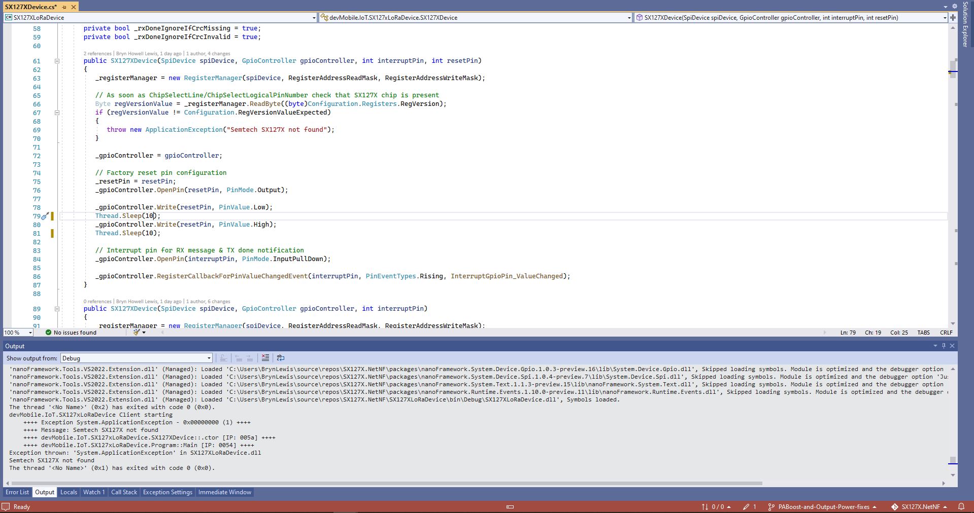
One afternoon the issue occurred several times in a row, the application wouldn’t startup because the SX127X device detection failed and message transmission was also not being confirmed.(TX Done).
Visual Studio output windows with SX127X detection failure
Visual Studio output windows with no Transmit confirmations
public SX127XDevice(SpiDevice spiDevice, GpioController gpioController, int interruptPin, int resetPin)
{
	_gpioController = gpioController;

	// Factory reset pin configuration
	_resetPin = resetPin;
	_gpioController.OpenPin(resetPin, PinMode.Output);

	_gpioController.Write(resetPin, PinValue.Low);
	Thread.Sleep(20);
	_gpioController.Write(resetPin, PinValue.High);
	Thread.Sleep(100);

	_registerManager = new RegisterManager(spiDevice, RegisterAddressReadMask, RegisterAddressWriteMask);

	// Once the pins setup check that SX127X chip is present
	Byte regVersionValue = _registerManager.ReadByte((byte)Configuration.Registers.RegVersion);
	if (regVersionValue != Configuration.RegVersionValueExpected)
	{
		throw new ApplicationException("Semtech SX127X not found");
	}

	// Interrupt pin for RX message & TX done notification
	_gpioController.OpenPin(interruptPin, PinMode.InputPullDown);

	_gpioController.RegisterCallbackForPinValueChangedEvent(interruptPin, PinEventTypes.Rising, InterruptGpioPin_ValueChanged);
}
I could single step through the code and inspect variables with the debugger and it looks like a timing issue with order of the strobing of the reset pin and the initialisation of the RegisterManager. I’ll spend and hour starting and stopping the application, then smoke test the code for 24 hours with a couple of other devices generating traffic just to check.
namespace devMobile.IoT.SX127xLoRaDevice
{
	using System;
	using System.Text;
	using System.Threading;

	class Program
	{
		private const double Frequency = 915000000.0;
#if ESP32_WROOM_32_LORA_1_CHANNEL
      private const int SpiBusId = 1;
#endif
#if NETDUINO3_WIFI
		private const int SpiBusId = 2;
#endif
#if ST_STM32F769I_DISCOVERY
		private const int SpiBusId = 2;
#endif
		private static SX127XDevice sx127XDevice;

		static void Main(string[] args)
		{
			int SendCount = 0;
#if ESP32_WROOM_32_LORA_1_CHANNEL // No reset line for this device as it isn't connected on SX127X
			int chipSelectLine = Gpio.IO16;
			int interruptPinNumber = Gpio.IO26;
#endif
#if NETDUINO3_WIFI
			// Arduino D10->PB10
			int chipSelectLine = PinNumber('B', 10);
			// Arduino D9->PE5
			int resetPinNumber = PinNumber('E', 5);
			// Arduino D2 -PA3
			int interruptPinNumber = PinNumber('A', 3);
#endif
#if ST_STM32F769I_DISCOVERY
			// Arduino D10->PA11
			int chipSelectLine = PinNumber('A', 11);
			// Arduino D9->PH6
			int resetPinNumber = PinNumber('H', 6);
			// Arduino D2->PA4
			int interruptPinNumber = PinNumber('J', 1);
#endif
			Console.WriteLine("devMobile.IoT.SX127xLoRaDevice Client starting");

			try
			{
#if ESP32_WROOM_32_LORA_1_CHANNEL
				Configuration.SetPinFunction(Gpio.IO12, DeviceFunction.SPI1_MISO);
				Configuration.SetPinFunction(Gpio.IO13, DeviceFunction.SPI1_MOSI);
				Configuration.SetPinFunction(Gpio.IO14, DeviceFunction.SPI1_CLOCK);

				sx127XDevice = new SX127XDevice(SpiBusId, chipSelectLine, interruptPinNumber);
#endif
#if NETDUINO3_WIFI || ST_STM32F769I_DISCOVERY
				sx127XDevice = new SX127XDevice(SpiBusId, chipSelectLine, interruptPinNumber, resetPinNumber);
#endif

				sx127XDevice.Initialise(SX127XDevice.RegOpModeMode.ReceiveContinuous,
							Frequency,
							lnaGain: SX127XDevice.RegLnaLnaGain.G3,
							lnaBoost:true,
							powerAmplifier: SX127XDevice.PowerAmplifier.PABoost,
							rxPayloadCrcOn: true,
							rxDoneignoreIfCrcMissing: false
							);

#if DEBUG
				sx127XDevice.RegisterDump();
#endif

				sx127XDevice.OnReceive += SX127XDevice_OnReceive;
				sx127XDevice.Receive();
				sx127XDevice.OnTransmit += SX127XDevice_OnTransmit;

				Thread.Sleep(500);

				while (true)
				{
					string messageText = $"Hello LoRa from .NET nanoFramework {SendCount += 1}!";

					byte[] messageBytes = UTF8Encoding.UTF8.GetBytes(messageText);
					//Console.WriteLine($"{DateTime.UtcNow:HH:mm:ss}-TX {messageBytes.Length} byte message {messageText}");
					//sx127XDevice.Send(messageBytes);

					Thread.Sleep(50000);
				}
			}
			catch (Exception ex)
			{
				Console.WriteLine(ex.Message);
			}
		}

		private static void SX127XDevice_OnReceive(object sender, SX127XDevice.OnDataReceivedEventArgs e)
		{
			try
			{
				// Remove unprintable characters from messages
				for (int index = 0; index < e.Data.Length; index++)
				{
					if ((e.Data[index] < 0x20) || (e.Data[index] > 0x7E))
					{
						e.Data[index] = 0x7C;
					}
				}

				string messageText = UTF8Encoding.UTF8.GetString(e.Data, 0, e.Data.Length);

				Console.WriteLine($"{DateTime.UtcNow:HH:mm:ss}-RX PacketSnr {e.PacketSnr:0.0} Packet RSSI {e.PacketRssi}dBm RSSI {e.Rssi}dBm = {e.Data.Length} byte message {messageText}");
			}
			catch (Exception ex)
			{
				Console.WriteLine(ex.Message);
			}
		}

		private static void SX127XDevice_OnTransmit(object sender, SX127XDevice.OnDataTransmitedEventArgs e)
		{
			sx127XDevice.SetMode(SX127XDevice.RegOpModeMode.ReceiveContinuous);

			Console.WriteLine($"{DateTime.UtcNow:HH:mm:ss}-TX Done");
		}

#if NETDUINO3_WIFI || ST_STM32F769I_DISCOVERY
		static int PinNumber(char port, byte pin)
		{
			if (port < 'A' || port > 'J')
				throw new ArgumentException();

			return ((port - 'A') * 16) + pin;
		}
#endif
	}
}
The sample application shows how to configure the library for different devices (SPI port, interrupt pin and optional reset pin) then send/receive payloads. The library is intended to be initialised then run for long periods of time (I’m looking at a month long soak test next) rather than changing configuration while running. The initialise method has many parameters which have “reasonable” default values. (Posts coming about optimising power consumption and range).
The TransmitInterrupt application loads the message to be sent into the First In First Out(FIFO) buffer, RegDioMapping1 is set to interrupt onTxDone(PacketSent-00), then RegRegOpMode-Mode is set to Transmit. When the message has been sent InterruptGpioPin_ValueChanged is called, and the TxDone(0b00001000) flag is set in the RegIrqFlags register.
The ReceiveInterrupt application sets the RegDioMapping1 to interrupt on RxDone(PacketReady-00), then the RegRegOpMode-Mode is set to Receive(TX-101). When a message is received InterruptGpioPin_ValueChanged is called, with the RxDone(0b00001000) flag set in the RegIrqFlags register, and then the message is read from First In First Out(FIFO) buffer.
namespace devMobile.IoT.SX127x.ReceiveTransmitInterrupt
{
...
   public sealed class SX127XDevice
   {
...
      public SX127XDevice(int busId, int chipSelectLine, int interruptPin, int resetPin)
      {
         var settings = new SpiConnectionSettings(busId, chipSelectLine)
         {
            ClockFrequency = 1000000,
            Mode = SpiMode.Mode0,// From SemTech docs pg 80 CPOL=0, CPHA=0
            SharingMode = SpiSharingMode.Shared
         };

         SX127XTransceiver = new SpiDevice(settings);

         GpioController gpioController = new GpioController();


         // Factory reset pin configuration
         gpioController.OpenPin(resetPin, PinMode.Output);

         gpioController.Write(resetPin, PinValue.Low);
         Thread.Sleep(20);
         gpioController.Write(resetPin, PinValue.High);
         Thread.Sleep(20);

         // Interrupt pin for RX message & TX done notification
         gpioController.OpenPin(interruptPin, PinMode.InputPullDown);

         gpioController.RegisterCallbackForPinValueChangedEvent(interruptPin, PinEventTypes.Rising, InterruptGpioPin_ValueChanged);
      }
...
   }

      private void InterruptGpioPin_ValueChanged(object sender, PinValueChangedEventArgs e)
      {
         byte irqFlags = this.ReadByte(0x12); // RegIrqFlags
         Debug.WriteLine($"RegIrqFlags 0X{irqFlags:x2}");

         if ((irqFlags & 0b01000000) == 0b01000000)  // RxDone
         {
            Debug.WriteLine("Receive-Message");
            byte currentFifoAddress = this.ReadByte(0x10); // RegFifiRxCurrent
            this.WriteByte(0x0d, currentFifoAddress); // RegFifoAddrPtr

            byte numberOfBytes = this.ReadByte(0x13); // RegRxNbBytes

            // Allocate buffer for message
            byte[] messageBytes = this.ReadBytes(0X0, numberOfBytes);

            // Remove unprintable characters from messages
            for (int index = 0; index < messageBytes.Length; index++)
            {
               if ((messageBytes[index] < 0x20) || (messageBytes[index] > 0x7E))
               {
                  messageBytes[index] = 0x20;
               }
            }

            string messageText = UTF8Encoding.UTF8.GetString(messageBytes, 0, messageBytes.Length);
            Debug.WriteLine($"Received {messageBytes.Length} byte message {messageText}");
         }

         if ((irqFlags & 0b00001000) == 0b00001000)  // TxDone
         {
            this.WriteByte(0x01, 0b10000101); // RegOpMode set LoRa & RxContinuous
            Debug.WriteLine("Transmit-Done");
         }

         this.WriteByte(0x40, 0b00000000); // RegDioMapping1 0b00000000 DI0 RxReady & TxReady
         this.WriteByte(0x12, 0xff);// RegIrqFlags
      }

   public class Program
   {
...
   #if NETDUINO3_WIFI
      private const int SpiBusId = 2;
#endif
...

      public static void Main()
      {
         int SendCount = 0;
...
#if NETDUINO3_WIFI
         // Arduino D10->PB10
         int chipSelectLine = PinNumber('B', 10);
         // Arduino D9->PE5
         int resetPinNumber = PinNumber('E', 5);
         // Arduino D2 -PA3
         int interruptPinNumber = PinNumber('A', 3);
#endif
...

       Debug.WriteLine("devMobile.IoT.SX127x.ReceiveTransmitInterrupt starting");

         try
         {
...
#if NETDUINO3_WIFI || ST_STM32F769I_DISCOVERY
            SX127XDevice sx127XDevice = new SX127XDevice(SpiBusId, chipSelectLine, interruptPinNumber, resetPinNumber);
#endif
            Thread.Sleep(500);

            // Put device into LoRa + Sleep mode
            sx127XDevice.WriteByte(0x01, 0b10000000); // RegOpMode

            // Set the frequency to 915MHz
            byte[] frequencyWriteBytes = { 0xE4, 0xC0, 0x00 }; // RegFrMsb, RegFrMid, RegFrLsb
            sx127XDevice.WriteBytes(0x06, frequencyWriteBytes);

            // More power PA Boost
            sx127XDevice.WriteByte(0x09, 0b10000000); // RegPaConfig

            sx127XDevice.WriteByte(0x01, 0b10000101); // RegOpMode set LoRa & RxContinuous

            while (true)
            {
               // Set the Register Fifo address pointer
               sx127XDevice.WriteByte(0x0E, 0x00); // RegFifoTxBaseAddress

               // Set the Register Fifo address pointer
               sx127XDevice.WriteByte(0x0D, 0x0); // RegFifoAddrPtr

               string messageText = $"Hello LoRa {SendCount += 1}!";

               // load the message into the fifo
               byte[] messageBytes = UTF8Encoding.UTF8.GetBytes(messageText);
               sx127XDevice.WriteBytes(0x0, messageBytes); // RegFifo

               // Set the length of the message in the fifo
               sx127XDevice.WriteByte(0x22, (byte)messageBytes.Length); // RegPayloadLength
               sx127XDevice.WriteByte(0x40, 0b01000000); // RegDioMapping1 0b00000000 DI0 RxReady & TxReady
               sx127XDevice.WriteByte(0x01, 0b10000011); // RegOpMode

               Debug.WriteLine($"Sending {messageBytes.Length} bytes message {messageText}");

               Thread.Sleep(10000);
            }
         }
         catch (Exception ex)
         {
            Debug.WriteLine(ex.Message);
         }
      }
...
   }
}
ReceiveTransmitInterrupt application output
The ReceiveTransmitInterrupt application combines the functionality TransmitInterrupt and ReceiveInterrupt programs. The key differences are the RegDioMapping1 setup and in InterruptGpioPin_ValueChanged where the TxDone & RxDone flags in the RegIrqFlags register specify how the interrupt is handled.