Random wanderings through Microsoft Azure esp. PaaS plumbing, the IoT bits, AI on Micro controllers, AI on Edge Devices, .NET nanoFramework, .NET Core on *nix and ML.NET+ONNX
I modified the code to allow the Instrumentation Key input via a command line parameter or from the ApplicationInsights.config file.
class Program
{
   private static ILog log = log4net.LogManager.GetLogger(System.Reflection.MethodBase.GetCurrentMethod().DeclaringType);

   static void Main(string[] args)
   {
      if (( args.Length != 0) && (args.Length != 1 ))
      {
         Console.WriteLine("Usage AzureApplicationInsightsClientConsole");
         Console.WriteLine("      AzureApplicationInsightsClientConsole <instrumentationKey>");
         return;
      }

      if (args.Length == 1)
      {
         TelemetryConfiguration.Active.InstrumentationKey = args[0];
      }

      log.Debug("This is a Log4Net Debug message");
      log.Info("This is a Log4Net Info message");
      log.Warn("This is a Log4Net Warning message");
      log.Error("This is an Log4Net Error message");
      log.Fatal("This is a Log4Net Fatal message");

      TelemetryConfiguration.Active.TelemetryChannel.Flush();

      Console.WriteLine("Press <enter> to exit>");
      Console.ReadLine();
   }
}
I updated the Log4Net setup to use the ManagedColoredConsoleAppender which required a couple of modifications to the Log4Net.config file. (I had to remove HighIntensity)
This post revisits a previous post “Don’t forget to flush” Application insights and shows how to configure the instrumentation key in code or via the ApplicationInsights.config file.
 class Program
   {
      static void Main(string[] args)
      {
#if INSTRUMENTATION_KEY_TELEMETRY_CONFIGURATION
         if (args.Length != 1)
         {
            Console.WriteLine("Usage AzureApplicationInsightsClientConsole <instrumentationKey>");
            return;
         }

         TelemetryConfiguration telemetryConfiguration = new TelemetryConfiguration(args[0]);
         TelemetryClient telemetryClient = new TelemetryClient(telemetryConfiguration);
         telemetryClient.TrackTrace("INSTRUMENTATION_KEY_TELEMETRY_CONFIGURATION", SeverityLevel.Information);
#endif
#if INSTRUMENTATION_KEY_APPLICATION_INSIGHTS_CONFIG
         TelemetryClient telemetryClient = new TelemetryClient();
         telemetryClient.TrackTrace("INSTRUMENTATION_KEY_APPLICATION_INSIGHTS_CONFIG", SeverityLevel.Information);
#endif
         telemetryClient.TrackTrace("This is an AI API Verbose message", SeverityLevel.Verbose);
         telemetryClient.TrackTrace("This is an AI API Information message", SeverityLevel.Information);
         telemetryClient.TrackTrace("This is an AI API Warning message", SeverityLevel.Warning);
         telemetryClient.TrackTrace("This is an AI API Error message", SeverityLevel.Error);
         telemetryClient.TrackTrace("This is an AI API Critical message", SeverityLevel.Critical);

         telemetryClient.Flush();

         Console.WriteLine("Press <enter> to exit");
         Console.ReadLine();
      }
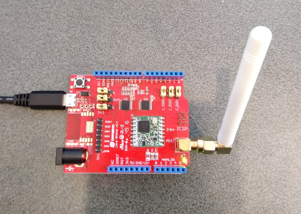
Dragino LoRa Shield for Arduino based test harness
A sample application which shows how to send/receive address/un-addresses payloads
//---------------------------------------------------------------------------------
// Copyright (c) March 2020, devMobile Software
//
// Licensed under the Apache License, Version 2.0 (the "License");
// you may not use this file except in compliance with the License.
// You may obtain a copy of the License at
//
//     http://www.apache.org/licenses/LICENSE-2.0
//
// Unless required by applicable law or agreed to in writing, software
// distributed under the License is distributed on an "AS IS" BASIS,
// WITHOUT WARRANTIES OR CONDITIONS OF ANY KIND, either express or implied.
// See the License for the specific language governing permissions and
// limitations under the License.
//
//---------------------------------------------------------------------------------
namespace devMobile.IoT.Rfm9x.LoRaDeviceClient
{
   using System;
   using System.Diagnostics;
   using System.Text;
   using System.Threading;

   using GHIElectronics.TinyCLR.Pins;

   using devMobile.IoT.Rfm9x;

   class Program
   {
      static void Main()
      {
			const string DeviceName = "FEZLoRa";
#if ADDRESSED_MESSAGES_PAYLOAD
			const string HostName = "LoRaIoT1";
#endif
			const double Frequency = 915000000.0;
			byte MessageCount = System.Byte.MaxValue;
			Rfm9XDevice rfm9XDevice = new Rfm9XDevice(FEZ.GpioPin.D10, FEZ.GpioPin.D9, FEZ.GpioPin.D2);

			rfm9XDevice.Initialise(Frequency, paBoost: true, rxPayloadCrcOn: true);
#if DEBUG
			rfm9XDevice.RegisterDump();
#endif

			rfm9XDevice.OnReceive += Rfm9XDevice_OnReceive;
#if ADDRESSED_MESSAGES_PAYLOAD
			rfm9XDevice.Receive(UTF8Encoding.UTF8.GetBytes(DeviceName));
#else
			rfm9XDevice.Receive();
#endif
			rfm9XDevice.OnTransmit += Rfm9XDevice_OnTransmit;

			Thread.Sleep(10000);

			while (true)
			{
				string messageText = string.Format("Hello from {0} ! {1}", DeviceName, MessageCount);
				MessageCount -= 1;

				byte[] messageBytes = UTF8Encoding.UTF8.GetBytes(messageText);
				Debug.WriteLine($"{DateTime.Now:HH:mm:ss}-TX {messageBytes.Length} byte message {messageText}");
#if ADDRESSED_MESSAGES_PAYLOAD
				rfm9XDevice.Send(UTF8Encoding.UTF8.GetBytes(HostName), messageBytes);
#else
				rfm9XDevice.Send(messageBytes);
#endif
				Thread.Sleep(10000);
			}
		}

		private static void Rfm9XDevice_OnReceive(object sender, Rfm9XDevice.OnDataReceivedEventArgs e)
		{
			try
			{
				string messageText = UTF8Encoding.UTF8.GetString(e.Data);

#if ADDRESSED_MESSAGES_PAYLOAD
				string addressText = UTF8Encoding.UTF8.GetString(e.Address);

				Debug.WriteLine($@"{DateTime.Now:HH:mm:ss}-RX From {addressText} PacketSnr {e.PacketSnr} Packet RSSI {e.PacketRssi}dBm RSSI {e.Rssi}dBm = {e.Data.Length} byte message ""{messageText}""");
#else
				Debug.WriteLine($@"{DateTime.Now:HH:mm:ss}-RX PacketSnr {e.PacketSnr} Packet RSSI {e.PacketRssi}dBm RSSI {e.Rssi}dBm = {e.Data.Length} byte message ""{messageText}""");
#endif
			}
			catch (Exception ex)
			{
				Debug.WriteLine(ex.Message);
			}
		}

		private static void Rfm9XDevice_OnTransmit(object sender, Rfm9XDevice.OnDataTransmitedEventArgs e)
		{
			Debug.WriteLine($"{DateTime.Now:HH:mm:ss}-TX Done");
		}
	}
}
For the final iteration of the “nasty” test harness I got the interrupts working for the transmitting and receiving of messages. It’s not quite simultaneous, the code sends a message every 10 seconds then goes back to receive continuous mode after each message has been sent.
      public Rfm9XDevice(int chipSelectPin, int resetPin, int interruptPin)
      {
         var settings = new SpiConnectionSettings()
         {
            ChipSelectType = SpiChipSelectType.Gpio,
            ChipSelectLine = chipSelectPin,
            Mode = SpiMode.Mode0,
            ClockFrequency = 500000,
            DataBitLength = 8,
            ChipSelectActiveState = false,
         };

         SpiController spiCntroller = SpiController.FromName(FEZ.SpiBus.Spi1);

         rfm9XLoraModem = spiCntroller.GetDevice(settings);

         // Factory reset pin configuration
         GpioController gpioController = GpioController.GetDefault();
         GpioPin resetGpioPin = gpioController.OpenPin(resetPin);
         resetGpioPin.SetDriveMode(GpioPinDriveMode.Output);
         resetGpioPin.Write(GpioPinValue.Low);
         Thread.Sleep(10);
         resetGpioPin.Write(GpioPinValue.High);
         Thread.Sleep(10);

         // Interrupt pin for RX message & TX done notification
         InterruptGpioPin = gpioController.OpenPin(interruptPin);
         resetGpioPin.SetDriveMode(GpioPinDriveMode.Input);

         InterruptGpioPin.ValueChanged += InterruptGpioPin_ValueChanged;
      }

      private void InterruptGpioPin_ValueChanged(GpioPin sender, GpioPinValueChangedEventArgs e)
      {
         if (e.Edge != GpioPinEdge.RisingEdge)
         {
            return;
         }

         byte irqFlags = this.RegisterReadByte(0x12); // RegIrqFlags
         Debug.WriteLine($"RegIrqFlags 0X{irqFlags:x2}");

         if ((irqFlags & 0b01000000) == 0b01000000)  // RxDone
         {
            Debug.WriteLine("Receive-Message");
            byte currentFifoAddress = this.RegisterReadByte(0x10); // RegFifiRxCurrent
            this.RegisterWriteByte(0x0d, currentFifoAddress); // RegFifoAddrPtr

            byte numberOfBytes = this.RegisterReadByte(0x13); // RegRxNbBytes

            // Allocate buffer for message
            byte[] messageBytes = this.RegisterRead(0X0, numberOfBytes);

            string messageText = UTF8Encoding.UTF8.GetString(messageBytes);
            Debug.WriteLine($"Received {messageBytes.Length} byte message {messageText}");
         }

         if ((irqFlags & 0b00001000) == 0b00001000)  // TxDone
         {
            this.RegisterWriteByte(0x01, 0b10000101); // RegOpMode set LoRa & RxContinuous
            Debug.WriteLine("Transmit-Done");
         }

         this.RegisterWriteByte(0x40, 0b00000000); // RegDioMapping1 0b00000000 DI0 RxReady & TxReady
         this.RegisterWriteByte(0x12, 0xff);// RegIrqFlags
      }

…

      public void RegisterDump()
      {
         Debug.WriteLine("Register dump");
         for (byte registerIndex = 0; registerIndex <= 0x42; registerIndex++)
         {
            byte registerValue = this.RegisterReadByte(registerIndex);

            Debug.WriteLine($"Register 0x{registerIndex:x2} - Value 0X{registerValue:x2}");
         }
      }
   }

   class Program
   {
      static void Main()
      {
         Rfm9XDevice rfm9XDevice = new Rfm9XDevice(FEZ.GpioPin.D10, FEZ.GpioPin.D9, FEZ.GpioPin.D2);
         int sendCount = 0;

         // Put device into LoRa + Sleep mode
         rfm9XDevice.RegisterWriteByte(0x01, 0b10000000); // RegOpMode

         // Set the frequency to 915MHz
         byte[] frequencyWriteBytes = { 0xE4, 0xC0, 0x00 }; // RegFrMsb, RegFrMid, RegFrLsb
         rfm9XDevice.RegisterWrite(0x06, frequencyWriteBytes);

         rfm9XDevice.RegisterWriteByte(0x0F, 0x0); // RegFifoRxBaseAddress

         // More power PA Boost
         rfm9XDevice.RegisterWriteByte(0x09, 0b10000000); // RegPaConfig

         rfm9XDevice.RegisterWriteByte(0x01, 0b10000101); // RegOpMode set LoRa & RxContinuous

         while (true)
         {
            rfm9XDevice.RegisterWriteByte(0x0E, 0x0); // RegFifoTxBaseAddress

            // Set the Register Fifo address pointer
            rfm9XDevice.RegisterWriteByte(0x0D, 0x0); // RegFifoAddrPtr

            string messageText = $"Hello LoRa {sendCount += 1}!";

            // load the message into the fifo
            byte[] messageBytes = UTF8Encoding.UTF8.GetBytes(messageText);
            rfm9XDevice.RegisterWrite(0x0, messageBytes); // RegFifo

            // Set the length of the message in the fifo
            rfm9XDevice.RegisterWriteByte(0x22, (byte)messageBytes.Length); // RegPayloadLength
            rfm9XDevice.RegisterWriteByte(0x40, 0b01000000); // RegDioMapping1 0b00000000 DI0 RxReady & TxReady
            rfm9XDevice.RegisterWriteByte(0x01, 0b10000011); // RegOpMode

            Debug.WriteLine($"Sending {messageBytes.Length} bytes message {messageText}");

            Thread.Sleep(10000);
         }
      }
   }
The diagnostic output shows inbound and outbound messages (Arduino then Meadow diagnostics)
Starting with the TransmitBasic sample application I modified the code so that a hardware interrupt (specified in RegDioMapping1) was generated on TxDone (FIFO Payload Transmission completed).
The application inserts a message into the RFM95 transmit FIFO every 10 seconds with confirmation of transmission displayed shortly afterwards
      public Rfm9XDevice(int chipSelectPin, int resetPin, int interruptPin)
      {
         var settings = new SpiConnectionSettings()
         {
            ChipSelectType = SpiChipSelectType.Gpio,
            ChipSelectLine = chipSelectPin,
            Mode = SpiMode.Mode0,
            ClockFrequency = 500000,
            DataBitLength = 8,
            ChipSelectActiveState = false,
         };

         SpiController spiCntroller = SpiController.FromName(FEZ.SpiBus.Spi1);

         rfm9XLoraModem = spiCntroller.GetDevice(settings);

         // Factory reset pin configuration
         GpioController gpioController = GpioController.GetDefault();
         GpioPin resetGpioPin = gpioController.OpenPin(resetPin);
         resetGpioPin.SetDriveMode(GpioPinDriveMode.Output);
         resetGpioPin.Write(GpioPinValue.Low);
         Thread.Sleep(10);
         resetGpioPin.Write(GpioPinValue.High);
         Thread.Sleep(10);

         // Interrupt pin for RX message & TX done notification
         InterruptGpioPin = gpioController.OpenPin(interruptPin);
         resetGpioPin.SetDriveMode(GpioPinDriveMode.Input);

         InterruptGpioPin.ValueChanged += InterruptGpioPin_ValueChanged;
      }

      private void InterruptGpioPin_ValueChanged(GpioPin sender, GpioPinValueChangedEventArgs e)
      {
         if (e.Edge != GpioPinEdge.RisingEdge)
         {
            return;
         }

         byte irqFlags = this.RegisterReadByte(0x12); // RegIrqFlags
         Debug.WriteLine($"RegIrqFlags 0X{irqFlags:x2}");

         if ((irqFlags & 0b00001000) == 0b00001000)  // TxDone
         {
            Debug.WriteLine("Transmit-Done");
         }

         this.RegisterWriteByte(0x12, 0xff);// RegIrqFlags
      }
…
   class Program
   {
      static void Main()
      {
         Rfm9XDevice rfm9XDevice = new Rfm9XDevice(FEZ.GpioPin.D10, FEZ.GpioPin.D9, FEZ.GpioPin.D2);
         int SendCount = 0;

         // Put device into LoRa + Sleep mode
         rfm9XDevice.RegisterWriteByte(0x01, 0b10000000); // RegOpMode

         // Set the frequency to 915MHz
         byte[] frequencyWriteBytes = { 0xE4, 0xC0, 0x00 }; // RegFrMsb, RegFrMid, RegFrLsb
         rfm9XDevice.RegisterWrite(0x06, frequencyWriteBytes);

         // More power PA Boost
         rfm9XDevice.RegisterWriteByte(0x09, 0b10000000); // RegPaConfig

         // Interrupt on TxDone
         rfm9XDevice.RegisterWriteByte(0x40, 0b01000000); // RegDioMapping1 0b00000000 DI0 TxDone

         while (true)
         {
            // Set the Register Fifo address pointer
            rfm9XDevice.RegisterWriteByte(0x0E, 0x00); // RegFifoTxBaseAddress

            // Set the Register Fifo address pointer
            rfm9XDevice.RegisterWriteByte(0x0D, 0x0); // RegFifoAddrPtr

            string messageText = $"Hello LoRa {SendCount += 1}!";

            // load the message into the fifo
            byte[] messageBytes = UTF8Encoding.UTF8.GetBytes(messageText);
            rfm9XDevice.RegisterWrite(0x0, messageBytes); // RegFifo

            // Set the length of the message in the fifo
            rfm9XDevice.RegisterWriteByte(0x22, (byte)messageBytes.Length); // RegPayloadLength
            Debug.WriteLine($"Sending {messageBytes.Length} bytes message {messageText}");
            rfm9XDevice.RegisterWriteByte(0x01, 0b10000011); // RegOpMode

            Thread.Sleep(10000);
         }
      }
   }
Now that I’m confident my hardware is all working as expected the next step will be building a client which has a receive and transmit interrupt handler.
This proof of concept (PoC) was to confirm I could configure the Semtech 127X then handle the received messages using a TinyCLR GpioPinValueChangedEventHandler.
   public sealed class Rfm9XDevice
   {
      private SpiDevice rfm9XLoraModem;
      private GpioPin InterruptGpioPin = null;
      private const byte RegisterAddressReadMask = 0X7f;
      private const byte RegisterAddressWriteMask = 0x80;

      public Rfm9XDevice(int chipSelectPin, int resetPin, int interruptPin)
      {
         var settings = new SpiConnectionSettings()
         {
            ChipSelectType = SpiChipSelectType.Gpio,
            ChipSelectLine = chipSelectPin,
            Mode = SpiMode.Mode0,
            ClockFrequency = 500000,
            DataBitLength = 8,
            ChipSelectActiveState = false,
         };

         SpiController spiCntroller = SpiController.FromName(FEZ.SpiBus.Spi1);

         rfm9XLoraModem = spiCntroller.GetDevice(settings);

         // Factory reset pin configuration
         GpioController gpioController = GpioController.GetDefault();
         GpioPin resetGpioPin = gpioController.OpenPin(resetPin);
         resetGpioPin.SetDriveMode(GpioPinDriveMode.Output);
         resetGpioPin.Write(GpioPinValue.Low);
         Thread.Sleep(10);
         resetGpioPin.Write(GpioPinValue.High);
         Thread.Sleep(10);

         // Interrupt pin for RX message & TX done notification
         InterruptGpioPin = gpioController.OpenPin(interruptPin);
         resetGpioPin.SetDriveMode(GpioPinDriveMode.Input);

         InterruptGpioPin.ValueChanged += InterruptGpioPin_ValueChanged;
      }

      private void InterruptGpioPin_ValueChanged(GpioPin sender, GpioPinValueChangedEventArgs e)
      {
         if (e.Edge != GpioPinEdge.RisingEdge)
         {
            return;
         }

         byte irqFlags = this.RegisterReadByte(0x12); // RegIrqFlags
         Debug.WriteLine($"RegIrqFlags 0X{irqFlags:x2}");
         if ((irqFlags & 0b01000000) == 0b01000000)  // RxDone
         {
            Debug.WriteLine("Receive-Message");
            byte currentFifoAddress = this.RegisterReadByte(0x10); // RegFifiRxCurrent
            this.RegisterWriteByte(0x0d, currentFifoAddress); // RegFifoAddrPtr

            byte numberOfBytes = this.RegisterReadByte(0x13); // RegRxNbBytes

            // Get number of bytes in the message
            byte[] messageBytes = this.RegisterRead(0x00, numberOfBytes);

            string messageText = UTF8Encoding.UTF8.GetString(messageBytes);
            Debug.WriteLine($"Received {messageBytes.Length} byte message {messageText}");
         }

         this.RegisterWriteByte(0x12, 0xff);// RegIrqFlags
      }
...
   class Program
   {
      static void Main()
      {
         Rfm9XDevice rfm9XDevice = new Rfm9XDevice(FEZ.GpioPin.D10, FEZ.GpioPin.D9, FEZ.GpioPin.D2);

         // Put device into LoRa + Sleep mode
         rfm9XDevice.RegisterWriteByte(0x01, 0b10000000); // RegOpMode

         // Set the frequency to 915MHz
         byte[] frequencyWriteBytes = { 0xE4, 0xC0, 0x00 }; // RegFrMsb, RegFrMid, RegFrLsb
         rfm9XDevice.RegisterWrite(0x06, frequencyWriteBytes);

         rfm9XDevice.RegisterWriteByte(0x0F, 0x0); // RegFifoRxBaseAddress

         rfm9XDevice.RegisterWriteByte(0x40, 0b00000000); // RegDioMapping1 0b00000000 DI0 RxReady & TxReady

         rfm9XDevice.RegisterWriteByte(0x01, 0b10000101); // RegOpMode set LoRa & RxContinuous

         rfm9XDevice.RegisterDump();

         Debug.WriteLine("Receive-Wait");
         Thread.Sleep(Timeout.Infinite);
      }
   }
The output in the output debug window looked like this
'C:\Users\BrynLewis\source\repos\RFM9X.TinyCLR\ReceiveInterrupt\bin\Debug\pe\..\ReceiveInterrupt.exe', Symbols loaded.
The thread '<No Name>' (0x2) has exited with code 0 (0x0).
Register dump
Register 0x00 - Value 0X88
Register 0x01 - Value 0X85
Register 0x02 - Value 0X1a
..
Register 0x41 - Value 0X00
Register 0x42 - Value 0X12
Receive-Wait
RegIrqFlags 0X50
Receive-Message
Received 15 byte message HeLoRa World! 0
RegIrqFlags 0X50
Receive-Message
Received 15 byte message HeLoRa World! 2
RegIrqFlags 0X50
Receive-Message
Received 15 byte message HeLoRa World! 4
RegIrqFlags 0X50
Receive-Message
Received 15 byte message HeLoRa World! 6
RegIrqFlags 0X50
Receive-Message
Received 15 byte message HeLoRa World! 8
RegIrqFlags 0X50
Receive-Message
Received 16 byte message HeLoRa World! 10
RegIrqFlags 0X50
Receive-Message
Received 16 byte message HeLoRa World! 12
Next steps will be wiring up the transmit done interrupt, then building a full featured client based on my Windows 10 IoT Core library.
/*
  LoRa Duplex communication with Sync Word

  Sends a message every half second, and polls continually
  for new incoming messages. Sets the LoRa radio's Sync Word.

  Spreading factor is basically the radio's network ID. Radios with different
  Sync Words will not receive each other's transmissions. This is one way you
  can filter out radios you want to ignore, without making an addressing scheme.

  See the Semtech datasheet, http://www.semtech.com/images/datasheet/sx1276.pdf
  for more on Sync Word.

  created 28 April 2017
  by Tom Igoe
*/
#include <stdlib.h>
#include <LoRa.h>
const int csPin = PA4;          // LoRa radio chip select
const int resetPin = PC13;       // LoRa radio reset
const int irqPin = PA11;         // change for your board; must be a hardware interrupt pin

byte msgCount = 0;            // count of outgoing messages
int interval = 2000;          // interval between sends
long lastSendTime = 0;        // time of last packet send

void setup() {
  Serial.begin(9600);                   // initialize serial
  while (!Serial);

  Serial.println("LoRa Duplex - Set sync word");

  // override the default CS, reset, and IRQ pins (optional)
  LoRa.setPins(csPin, resetPin, irqPin);// set CS, reset, IRQ pin

  if (!LoRa.begin(915E6)) {             // initialize ratio at 915 MHz
    Serial.println("LoRa init failed. Check your connections.");
    while (true);                       // if failed, do nothing
  }

  LoRa.setSyncWord(0x12);           // ranges from 0-0xFF, default 0x34, see API docs

  LoRa.dumpRegisters(Serial);
  Serial.println("LoRa init succeeded.");
}

void loop() {
  if (millis() - lastSendTime > interval) {
    String message = "HeLoRa World! ";   // send a message
    message += msgCount;
    sendMessage(message);
    Serial.println("Sending " + message);
    lastSendTime = millis();            // timestamp the message
    interval = random(1000) + 10000;    // 10-11 seconds
    msgCount++;
  }

  // parse for a packet, and call onReceive with the result:
  onReceive(LoRa.parsePacket());
}

void sendMessage(String outgoing) {
  LoRa.beginPacket();                   // start packet
  LoRa.print(outgoing);                 // add payload
  LoRa.endPacket();                     // finish packet and send it
  msgCount++;                           // increment message ID
}

void onReceive(int packetSize) {
  if (packetSize == 0) return;          // if there's no packet, return

  // read packet header bytes:
  String incoming = "";

  while (LoRa.available()) {
    incoming += (char)LoRa.read();
  }

  Serial.println("Message: " + incoming);
  Serial.println("RSSI: " + String(LoRa.packetRssi()));
  Serial.println("Snr: " + String(LoRa.packetSnr()));
  Serial.println();
}
The FEZT-18N application
   class Program
   {
      static void Main()
      {
         Rfm9XDevice rfm9XDevice = new Rfm9XDevice(FEZ.GpioPin.D10, FEZ.GpioPin.D9);
         int SendCount = 0;

         // Put device into LoRa + Sleep mode
         rfm9XDevice.RegisterWriteByte(0x01, 0b10000000); // RegOpMode

         // Set the frequency to 915MHz
         byte[] frequencyWriteBytes = { 0xE4, 0xC0, 0x00 }; // RegFrMsb, RegFrMid, RegFrLsb
         rfm9XDevice.RegisterWrite(0x06, frequencyWriteBytes);

         // More power PA Boost
         rfm9XDevice.RegisterWriteByte(0x09, 0b10000000); // RegPaConfig

         while (true)
         {
            rfm9XDevice.RegisterWriteByte(0x0E, 0x0); // RegFifoTxBaseAddress

            // Set the Register Fifo address pointer
            rfm9XDevice.RegisterWriteByte(0x0D, 0x0); // RegFifoAddrPtr

            string messageText = $"Hello LoRa {SendCount += 1}!";

            // load the message into the fifo
            byte[] messageBytes = UTF8Encoding.UTF8.GetBytes(messageText);
            rfm9XDevice.RegisterWrite(0x0, messageBytes); // RegFifo

            // Set the length of the message in the fifo
            rfm9XDevice.RegisterWriteByte(0x22, (byte)messageBytes.Length); // RegPayloadLength

            Debug.WriteLine($"Sending {messageBytes.Length} bytes message {messageText}");
            /// Set the mode to LoRa + Transmit
            rfm9XDevice.RegisterWriteByte(0x01, 0b10000011); // RegOpMode

            // Wait until send done, no timeouts in PoC
            Debug.WriteLine("Send-wait");
            byte IrqFlags = rfm9XDevice.RegisterReadByte(0x12); // RegIrqFlags
            while ((IrqFlags & 0b00001000) == 0)  // wait until TxDone cleared
            {
               Thread.Sleep(10);
               IrqFlags = rfm9XDevice.RegisterReadByte(0x12); // RegIrqFlags
               Debug.WriteLine(".");
            }
            rfm9XDevice.RegisterWriteByte(0x12, 0b00001000); // clear TxDone bit
            Debug.WriteLine("Send-Done");

            Thread.Sleep(30000);
         }
      }
Now that I could reliably dump all the Dragino shield registers I wanted to be able to configure the Semtech 1276/7/8/9 device and reset it back to factory settings.
A factory reset is done by strobing the reset pin on the device. To support this my Rfm9XDevice class constructor gained an additional parameter, the reset GPIO pin number (an integer not a “strongly typed” identifier).
Dragino Shield on FEZT18-N
To configure the RFM9X I wrote some wrapper functions for the FEZSPIAPI to read/write byte values, word values and arrays of bytes. The TinyCLR-OS APIs (Mar 2019) return an additional byte at the start of each reply which has to be removed.
Each method was tested by read/writing suitable register(s) in the device configuration (Needed to set it into LoRa mode first).
//---------------------------------------------------------------------------------
// Copyright (c) March 2020, devMobile Software
//
// Licensed under the Apache License, Version 2.0 (the "License");
// you may not use this file except in compliance with the License.
// You may obtain a copy of the License at
//
//     http://www.apache.org/licenses/LICENSE-2.0
//
// Unless required by applicable law or agreed to in writing, software
// distributed under the License is distributed on an "AS IS" BASIS,
// WITHOUT WARRANTIES OR CONDITIONS OF ANY KIND, either express or implied.
// See the License for the specific language governing permissions and
// limitations under the License.
//
//---------------------------------------------------------------------------------
namespace devMobile.IoT.Rfm9x.RegisterReadAndWrite
{
   using System;
   using System.Diagnostics;
   using System.Threading;
   using GHIElectronics.TinyCLR.Devices.Gpio;
   using GHIElectronics.TinyCLR.Devices.Spi;
   using GHIElectronics.TinyCLR.Pins;

   public sealed class Rfm9XDevice
   {
      private SpiDevice rfm9XLoraModem;
      private const byte RegisterAddressReadMask = 0X7f;
      private const byte RegisterAddressWriteMask = 0x80;

      public Rfm9XDevice(int chipSelectPin, int resetPin)
      {
         var settings = new SpiConnectionSettings()
         {
            ChipSelectType = SpiChipSelectType.Gpio,
            ChipSelectLine = chipSelectPin,
            Mode = SpiMode.Mode0,
            ClockFrequency = 500000,
            DataBitLength = 8,
            ChipSelectActiveState = false,
         };

         SpiController spiCntroller = SpiController.FromName(FEZ.SpiBus.Spi1);

         rfm9XLoraModem = spiCntroller.GetDevice(settings);

         // Factory reset pin configuration
         GpioController gpioController = GpioController.GetDefault();
         GpioPin resetGpioPin = gpioController.OpenPin(resetPin);
         resetGpioPin.SetDriveMode(GpioPinDriveMode.Output);
         resetGpioPin.Write(GpioPinValue.Low);
         Thread.Sleep(10);
         resetGpioPin.Write(GpioPinValue.High);
         Thread.Sleep(10);
      }

      public Byte RegisterReadByte(byte registerAddress)
      {
         byte[] writeBuffer = new byte[] { registerAddress &= RegisterAddressReadMask, 0x0 };
         byte[] readBuffer = new byte[writeBuffer.Length];
         Debug.Assert(rfm9XLoraModem != null);

         rfm9XLoraModem.TransferFullDuplex(writeBuffer, readBuffer);

         return readBuffer[1];
      }

      public ushort RegisterReadWord(byte address)
      {
         byte[] writeBuffer = new byte[] { address &= RegisterAddressReadMask, 0x0, 0x0 };
         byte[] readBuffer = new byte[writeBuffer.Length];
         Debug.Assert(rfm9XLoraModem != null);

         rfm9XLoraModem.TransferFullDuplex(writeBuffer, readBuffer);

         return (ushort)(readBuffer[2] + (readBuffer[1] << 8));
      }

      public byte[] RegisterRead(byte address, int length)
      {
         byte[] writeBuffer = new byte[length + 1];
         byte[] readBuffer = new byte[length + 1];
         byte[] repyBuffer = new byte[length];
         Debug.Assert(rfm9XLoraModem != null);

         writeBuffer[0] = address &= RegisterAddressReadMask;

         rfm9XLoraModem.TransferFullDuplex(writeBuffer, readBuffer);

         Array.Copy(readBuffer, 1, repyBuffer, 0, length);

         return repyBuffer;
      }

      public void RegisterWriteByte(byte address, byte value)
      {
         byte[] writeBuffer = new byte[] { address |= RegisterAddressWriteMask, value };
         Debug.Assert(rfm9XLoraModem != null);

         rfm9XLoraModem.Write(writeBuffer);
      }

      public void RegisterWriteWord(byte address, ushort value)
      {
         byte[] valueBytes = BitConverter.GetBytes(value);
         byte[] writeBuffer = new byte[] { address |= RegisterAddressWriteMask, valueBytes[0], valueBytes[1] };
         Debug.Assert(rfm9XLoraModem != null);

         rfm9XLoraModem.Write(writeBuffer);
      }

      public void RegisterWrite(byte address, byte[] bytes)
      {
         byte[] writeBuffer = new byte[1 + bytes.Length];
         Debug.Assert(rfm9XLoraModem != null);

         Array.Copy(bytes, 0, writeBuffer, 1, bytes.Length);
         writeBuffer[0] = address |= RegisterAddressWriteMask;

         rfm9XLoraModem.Write(writeBuffer);
      }

      public void RegisterDump()
      {
         Debug.WriteLine("Register dump");
         for (byte registerIndex = 0; registerIndex <= 0x42; registerIndex++)
         {
            byte registerValue = this.RegisterReadByte(registerIndex);

            Debug.WriteLine($"Register 0x{registerIndex:x2} - Value 0X{registerValue:x2}");
         }
      }
   }

   class Program
   {
      static void Main()
      {
         Rfm9XDevice rfm9XDevice = new Rfm9XDevice(FEZ.GpioPin.D10, FEZ.GpioPin.D9);

         rfm9XDevice.RegisterDump();

         while (true)
         {
            Debug.WriteLine("Read RegOpMode (read byte)");
            Byte regOpMode1 = rfm9XDevice.RegisterReadByte(0x1);
            Debug.WriteLine($"RegOpMode 0x{regOpMode1:x2}");

            Debug.WriteLine("Set LoRa mode and sleep mode (write byte)");
            rfm9XDevice.RegisterWriteByte(0x01, 0b10000000);

            Debug.WriteLine("Read RegOpMode (read byte)");
            Byte regOpMode2 = rfm9XDevice.RegisterReadByte(0x1);
            Debug.WriteLine($"RegOpMode 0x{regOpMode2:x2}");

            Debug.WriteLine("Read the preamble (read word)");
            ushort preamble = rfm9XDevice.RegisterReadWord(0x20);
            Debug.WriteLine($"Preamble 0x{preamble:x2}");

            Debug.WriteLine("Set the preamble to 0x80 (write word)");
            rfm9XDevice.RegisterWriteWord(0x20, 0x80);

            Debug.WriteLine("Read the center frequency (read byte array)");
            byte[] frequencyReadBytes = rfm9XDevice.RegisterRead(0x06, 5);
            Debug.WriteLine($"Frequency Msb 0x{frequencyReadBytes[0]:x2} Mid 0x{frequencyReadBytes[1]:x2} Lsb 0x{frequencyReadBytes[2]:x2}");

            Debug.WriteLine("Set the center frequency to 916MHz (write byte array)");
            byte[] frequencyWriteBytes = { 0xE4, 0xC0, 0x00 };
            rfm9XDevice.RegisterWrite(0x06, frequencyWriteBytes);

            rfm9XDevice.RegisterDump();

            Thread.Sleep(30000);
         }
      }
   }
}
The output of the application looked like this
'GHIElectronics.TinyCLR.VisualStudio.ProjectSystem.dll' (Managed): Loaded 'C:\Users\BrynLewis\source\repos\RFM9X.TinyCLR\RegisterReadAndWrite\bin\Debug\pe\..\GHIElectronics.TinyCLR.Native.dll'
'GHIElectronics.TinyCLR.VisualStudio.ProjectSystem.dll' (Managed): Loaded 'C:\Users\BrynLewis\source\repos\RFM9X.TinyCLR\RegisterReadAndWrite\bin\Debug\pe\..\GHIElectronics.TinyCLR.Devices.Gpio.dll'
'GHIElectronics.TinyCLR.VisualStudio.ProjectSystem.dll' (Managed): Loaded 'C:\Users\BrynLewis\source\repos\RFM9X.TinyCLR\RegisterReadAndWrite\bin\Debug\pe\..\GHIElectronics.TinyCLR.Devices.Spi.dll'
'GHIElectronics.TinyCLR.VisualStudio.ProjectSystem.dll' (Managed): Loaded 'C:\Users\BrynLewis\source\repos\RFM9X.TinyCLR\RegisterReadAndWrite\bin\Debug\pe\..\RegisterReadAndWrite.exe', Symbols loaded.
The thread '<No Name>' (0x2) has exited with code 0 (0x0).
Register dump
Register 0x00 - Value 0X00
Register 0x01 - Value 0X09
Register 0x02 - Value 0X1a
Register 0x03 - Value 0X0b
Register 0x04 - Value 0X00
Register 0x05 - Value 0X52
Register 0x06 - Value 0X6c
Register 0x07 - Value 0X80
Register 0x08 - Value 0X00
Register 0x09 - Value 0X4f
Register 0x0a - Value 0X09
Register 0x0b - Value 0X2b
Register 0x0c - Value 0X20
Register 0x0d - Value 0X08
Register 0x0e - Value 0X02
Register 0x0f - Value 0X0a
Register 0x10 - Value 0Xff
Register 0x11 - Value 0X70
Register 0x12 - Value 0X15
Register 0x13 - Value 0X0b
Register 0x14 - Value 0X28
Register 0x15 - Value 0X0c
Register 0x16 - Value 0X12
Register 0x17 - Value 0X47
Register 0x18 - Value 0X32
Register 0x19 - Value 0X3e
Register 0x1a - Value 0X00
Register 0x1b - Value 0X00
Register 0x1c - Value 0X00
Register 0x1d - Value 0X00
Register 0x1e - Value 0X00
Register 0x1f - Value 0X40
Register 0x20 - Value 0X00
Register 0x21 - Value 0X00
Register 0x22 - Value 0X00
Register 0x23 - Value 0X00
Register 0x24 - Value 0X05
Register 0x25 - Value 0X00
Register 0x26 - Value 0X03
Register 0x27 - Value 0X93
Register 0x28 - Value 0X55
Register 0x29 - Value 0X55
Register 0x2a - Value 0X55
Register 0x2b - Value 0X55
Register 0x2c - Value 0X55
Register 0x2d - Value 0X55
Register 0x2e - Value 0X55
Register 0x2f - Value 0X55
Register 0x30 - Value 0X90
Register 0x31 - Value 0X40
Register 0x32 - Value 0X40
Register 0x33 - Value 0X00
Register 0x34 - Value 0X00
Register 0x35 - Value 0X0f
Register 0x36 - Value 0X00
Register 0x37 - Value 0X00
Register 0x38 - Value 0X00
Register 0x39 - Value 0Xf5
Register 0x3a - Value 0X20
Register 0x3b - Value 0X82
Register 0x3c - Value 0Xf3
Register 0x3d - Value 0X02
Register 0x3e - Value 0X80
Register 0x3f - Value 0X40
Register 0x40 - Value 0X00
Register 0x41 - Value 0X00
Register 0x42 - Value 0X12
Read RegOpMode (read byte)
RegOpMode 0x09
Set LoRa mode and sleep mode (write byte)
Read RegOpMode (read byte)
RegOpMode 0x80
Read the preamble (read word)
Preamble 0x08
Set the preamble to 0x80 (write word)
Read the center frequency (read byte array)
Frequency Msb 0x6c Mid 0x80 Lsb 0x00
Set the center frequency to 916MHz (write byte array)
Register dump
Register 0x00 - Value 0X01
Register 0x01 - Value 0X80
Register 0x02 - Value 0X1a
Register 0x03 - Value 0X0b
Register 0x04 - Value 0X00
Register 0x05 - Value 0X52
Register 0x06 - Value 0Xe4
Register 0x07 - Value 0Xc0
Register 0x08 - Value 0X00
Register 0x09 - Value 0X4f
Register 0x0a - Value 0X09
Register 0x0b - Value 0X2b
Register 0x0c - Value 0X20
Register 0x0d - Value 0X01
Register 0x0e - Value 0X80
Register 0x0f - Value 0X00
Register 0x10 - Value 0X00
Register 0x11 - Value 0X00
Register 0x12 - Value 0X00
Register 0x13 - Value 0X00
Register 0x14 - Value 0X00
Register 0x15 - Value 0X00
Register 0x17 - Value 0X00
Register 0x18 - Value 0X10
Register 0x19 - Value 0X00
Register 0x1a - Value 0X00
Register 0x1b - Value 0X00
Register 0x1c - Value 0X00
Register 0x1d - Value 0X72
Register 0x1e - Value 0X70
Register 0x1f - Value 0X64
Register 0x20 - Value 0X80
Register 0x21 - Value 0X00
Register 0x22 - Value 0X01
Register 0x23 - Value 0Xff
Register 0x24 - Value 0X00
Register 0x25 - Value 0X00
Register 0x26 - Value 0X04
Register 0x27 - Value 0X00
Register 0x28 - Value 0X00
Register 0x29 - Value 0X00
Register 0x2a - Value 0X00
Register 0x2b - Value 0X00
Register 0x2c - Value 0X00
Register 0x2d - Value 0X50
Register 0x2e - Value 0X14
Register 0x2f - Value 0X45
Register 0x30 - Value 0X55
Register 0x31 - Value 0Xc3
Register 0x32 - Value 0X05
Register 0x33 - Value 0X27
Register 0x34 - Value 0X1c
Register 0x35 - Value 0X0a
Register 0x36 - Value 0X03
Register 0x37 - Value 0X0a
Register 0x38 - Value 0X42
Register 0x39 - Value 0X12
Register 0x3a - Value 0X49
Register 0x3b - Value 0X1d
Register 0x3c - Value 0X00
Register 0x3d - Value 0Xaf
Register 0x3e - Value 0X00
Register 0x3f - Value 0X00
Register 0x40 - Value 0X00
Register 0x41 - Value 0X00
Register 0x42 - Value 0X12
The next step is to extract the SPI register access functionality into a module and configure the bare minimum of settings required to get the SX127X to transmit.
Next step was to dump all registers (0x00 thru 0x42) of the SX1276/7/8/9 device.
//---------------------------------------------------------------------------------
// Copyright (c) March 2020, devMobile Software
//
// Licensed under the Apache License, Version 2.0 (the "License");
// you may not use this file except in compliance with the License.
// You may obtain a copy of the License at
//
//     http://www.apache.org/licenses/LICENSE-2.0
//
// Unless required by applicable law or agreed to in writing, software
// distributed under the License is distributed on an "AS IS" BASIS,
// WITHOUT WARRANTIES OR CONDITIONS OF ANY KIND, either express or implied.
// See the License for the specific language governing permissions and
// limitations under the License.
//
//---------------------------------------------------------------------------------
namespace devMobile.IoT.Rfm9x.RegisterScan
{
   using System;
   using System.Diagnostics;
   using System.Threading;
   using GHIElectronics.TinyCLR.Devices.Spi;
   using GHIElectronics.TinyCLR.Pins;

   public sealed class Rfm9XDevice
   {
      private SpiDevice rfm9XLoraModem;

      public Rfm9XDevice(int chipSelectPin)
      {
         var settings = new SpiConnectionSettings()
         {
            ChipSelectType = SpiChipSelectType.Gpio,
            ChipSelectLine = chipSelectPin,
            Mode = SpiMode.Mode0,
            ClockFrequency = 500000,
            DataBitLength = 8,
            ChipSelectActiveState = false,
         };

         SpiController spiCntroller = SpiController.FromName(FEZ.SpiBus.Spi1);

         rfm9XLoraModem = spiCntroller.GetDevice(settings);
      }

      public Byte RegisterReadByte(byte registerAddress)
      {
         byte[] writeBuffer = new byte[] { registerAddress, 0x0 };
         byte[] readBuffer = new byte[writeBuffer.Length];
         Debug.Assert(rfm9XLoraModem != null);

         rfm9XLoraModem.TransferFullDuplex(writeBuffer, readBuffer);

         return readBuffer[1];
      }
   }

   class Program
   {
      static void Main()
      {
         Rfm9XDevice rfm9XDevice = new Rfm9XDevice(FEZ.GpioPin.D10);

         while (true)
         {
            for (byte registerIndex = 0; registerIndex <= 0x42; registerIndex++)
            {
               byte registerValue = rfm9XDevice.RegisterReadByte(registerIndex);

               Debug.WriteLine($"Register 0x{registerIndex:x2} - Value 0X{registerValue:x2}");
            }
            Debug.WriteLine("");

            Thread.Sleep(10000);
         }
      }
   }
}
The output of the application looked like this
Found debugger!

Create TS.

Loading Deployment Assemblies.

Attaching deployed file.

   Assembly: mscorlib (1.0.0.0)  Attaching deployed file.

   Assembly: GHIElectronics.TinyCLR.Devices.Spi (1.0.0.0)  Attaching deployed file.

   Assembly: GHIElectronics.TinyCLR.Devices.Gpio (1.0.0.0)  Attaching deployed file.

   Assembly: GHIElectronics.TinyCLR.Native (1.0.0.0)  Attaching deployed file.

   Assembly: RegisterScan (1.0.0.0)  Resolving.

The debugging target runtime is loading the application assemblies and starting execution.
Ready.

'GHIElectronics.TinyCLR.VisualStudio.ProjectSystem.dll' (Managed): Loaded 'C:\Users\BrynLewis\source\repos\RFM9X.TinyCLR\RegisterScan\bin\Debug\pe\..\GHIElectronics.TinyCLR.Native.dll'
'GHIElectronics.TinyCLR.VisualStudio.ProjectSystem.dll' (Managed): Loaded 'C:\Users\BrynLewis\source\repos\RFM9X.TinyCLR\RegisterScan\bin\Debug\pe\..\GHIElectronics.TinyCLR.Devices.Gpio.dll'
'GHIElectronics.TinyCLR.VisualStudio.ProjectSystem.dll' (Managed): Loaded 'C:\Users\BrynLewis\source\repos\RFM9X.TinyCLR\RegisterScan\bin\Debug\pe\..\GHIElectronics.TinyCLR.Devices.Spi.dll'
'GHIElectronics.TinyCLR.VisualStudio.ProjectSystem.dll' (Managed): Loaded 'C:\Users\BrynLewis\source\repos\RFM9X.TinyCLR\RegisterScan\bin\Debug\pe\..\RegisterScan.exe', Symbols loaded.
The thread '<No Name>' (0x2) has exited with code 0 (0x0).
Register 0x00 - Value 0X00
Register 0x01 - Value 0X09
Register 0x02 - Value 0X1a
Register 0x03 - Value 0X0b
Register 0x04 - Value 0X00
Register 0x05 - Value 0X52
Register 0x06 - Value 0X6c
Register 0x07 - Value 0X80
Register 0x08 - Value 0X00
Register 0x09 - Value 0X4f
Register 0x0a - Value 0X09
Register 0x0b - Value 0X2b
Register 0x0c - Value 0X20
Register 0x0d - Value 0X08
Register 0x0e - Value 0X02
Register 0x0f - Value 0X0a
Register 0x10 - Value 0Xff
Register 0x11 - Value 0X70
Register 0x12 - Value 0X15
Register 0x13 - Value 0X0b
Register 0x14 - Value 0X28
Register 0x15 - Value 0X0c
Register 0x16 - Value 0X12
Register 0x17 - Value 0X47
Register 0x18 - Value 0X32
Register 0x19 - Value 0X3e
Register 0x1a - Value 0X00
Register 0x1b - Value 0X00
Register 0x1c - Value 0X00
Register 0x1d - Value 0X00
Register 0x1e - Value 0X00
Register 0x1f - Value 0X40
Register 0x21 - Value 0X00
Register 0x22 - Value 0X00
Register 0x23 - Value 0X00
Register 0x24 - Value 0X05
Register 0x25 - Value 0X00
Register 0x26 - Value 0X03
Register 0x27 - Value 0X93
Register 0x28 - Value 0X55
Register 0x29 - Value 0X55
Register 0x2a - Value 0X55
Register 0x2b - Value 0X55
Register 0x2c - Value 0X55
Register 0x2d - Value 0X55
Register 0x2e - Value 0X55
Register 0x2f - Value 0X55
Register 0x30 - Value 0X90
Register 0x31 - Value 0X40
Register 0x32 - Value 0X40
Register 0x33 - Value 0X00
Register 0x34 - Value 0X00
Register 0x35 - Value 0X0f
Register 0x36 - Value 0X00
Register 0x37 - Value 0X00
Register 0x38 - Value 0X00
Register 0x39 - Value 0Xf5
Register 0x3a - Value 0X20
Register 0x3b - Value 0X82
Register 0x3c - Value 0Xf7
Register 0x3d - Value 0X02
Register 0x3e - Value 0X80
Register 0x3f - Value 0X40
Register 0x40 - Value 0X00
Register 0x41 - Value 0X00
Register 0x42 - Value 0X12
The device was not in LoRa mode (Bit 7 of RegOpMode 0x01) so the next step was to read and write registers so I could change its configuration.
Overall the SPI implementation was closer to Windows 10 IoT Core model than expected.