Random wanderings through Microsoft Azure esp. PaaS plumbing, the IoT bits, AI on Micro controllers, AI on Edge Devices, .NET nanoFramework, .NET Core on *nix and ML.NET+ONNX
The unpacking of the value standard particulate, environmental particulate and particle count values is fairly repetitive, but I will fix it in the next version.
Visual Studio 2022 Debug Output
The checksum calculation isn’t great even a simple cyclic redundancy check(CRC) would be an improvement on summing the 28 bytes of the payload.
//---------------------------------------------------------------------------------
// Copyright (c) January 2020, devMobile Software
//
// Licensed under the Apache License, Version 2.0 (the "License");
// you may not use this file except in compliance with the License.
// You may obtain a copy of the License at
//
//     http://www.apache.org/licenses/LICENSE-2.0
//
// Unless required by applicable law or agreed to in writing, software
// distributed under the License is distributed on an "AS IS" BASIS,
// WITHOUT WARRANTIES OR CONDITIONS OF ANY KIND, either express or implied.
// See the License for the specific language governing permissions and
// limitations under the License.
//
//---------------------------------------------------------------------------------
namespace devMobile.IoT.FieldGateway.Client
{
   using System;
   using System.Text;
   using System.Threading;

   using devMobile.IoT.Rfm9x;

   using Meadow;
   using Meadow.Devices;
   using Meadow.Foundation.Leds;
   using Meadow.Foundation.Sensors.Atmospheric;
   using Meadow.Hardware;
   using Meadow.Peripherals.Leds;

   public class MeadowClient : App<F7Micro, MeadowClient>
   {
      private const double Frequency = 915000000.0;
      private readonly byte[] fieldGatewayAddress = Encoding.UTF8.GetBytes("LoRaIoT1");
      private readonly byte[] deviceAddress = Encoding.UTF8.GetBytes("Meadow");
      private readonly Rfm9XDevice rfm9XDevice;
      private readonly TimeSpan periodTime = new TimeSpan(0, 0, 60);
      private readonly Sht31D sensor;
      private readonly ILed Led;

      public MeadowClient()
      {
         Led = new Led(Device, Device.Pins.OnboardLedGreen);

         try
         {
            sensor = new Sht31D(Device.CreateI2cBus());

            ISpiBus spiBus = Device.CreateSpiBus(500);

            rfm9XDevice = new Rfm9XDevice(Device, spiBus, Device.Pins.D09, Device.Pins.D10, Device.Pins.D12);

            rfm9XDevice.Initialise(Frequency, paBoost: true, rxPayloadCrcOn: true);
#if DEBUG
            rfm9XDevice.RegisterDump();
#endif
            rfm9XDevice.OnReceive += Rfm9XDevice_OnReceive;
            rfm9XDevice.Receive(deviceAddress);
            rfm9XDevice.OnTransmit += Rfm9XDevice_OnTransmit;
         }
         catch (Exception ex)
         {
            Console.WriteLine(ex.Message);
         }

         while (true)
         {
            sensor.Update();

            Console.WriteLine($"{DateTime.UtcNow:HH:mm:ss}-TX T:{sensor.Temperature:0.0}C H:{sensor.Humidity:0}%");

            string payload = $"t {sensor.Temperature:0.0},h {sensor.Humidity:0}";

            Led.IsOn = true;

            rfm9XDevice.Send(fieldGatewayAddress, Encoding.UTF8.GetBytes(payload));

            Thread.Sleep(periodTime);
         }
      }

      private void Rfm9XDevice_OnReceive(object sender, Rfm9XDevice.OnDataReceivedEventArgs e)
      {
         try
         {
            string addressText = UTF8Encoding.UTF8.GetString(e.Address);
            string addressHex = BitConverter.ToString(e.Address);
            string messageText = UTF8Encoding.UTF8.GetString(e.Data);

            Console.WriteLine($"{DateTime.UtcNow:HH:mm:ss}-RX PacketSnr {e.PacketSnr:0.0} Packet RSSI {e.PacketRssi}dBm RSSI {e.Rssi}dBm = {e.Data.Length} byte message {messageText}");
         }
         catch (Exception ex)
         {
            Console.WriteLine(ex.Message);
         }
      }

      private void Rfm9XDevice_OnTransmit(object sender, Rfm9XDevice.OnDataTransmitedEventArgs e)
      {
         Led.IsOn = false;

         Console.WriteLine("{0:HH:mm:ss}-TX Done", DateTime.Now);
      }
   }
}
The Meadow platform is a work in progress (Jan 2020) so I haven’t put any effort into minimising power consumption but will revisit this in a future post.
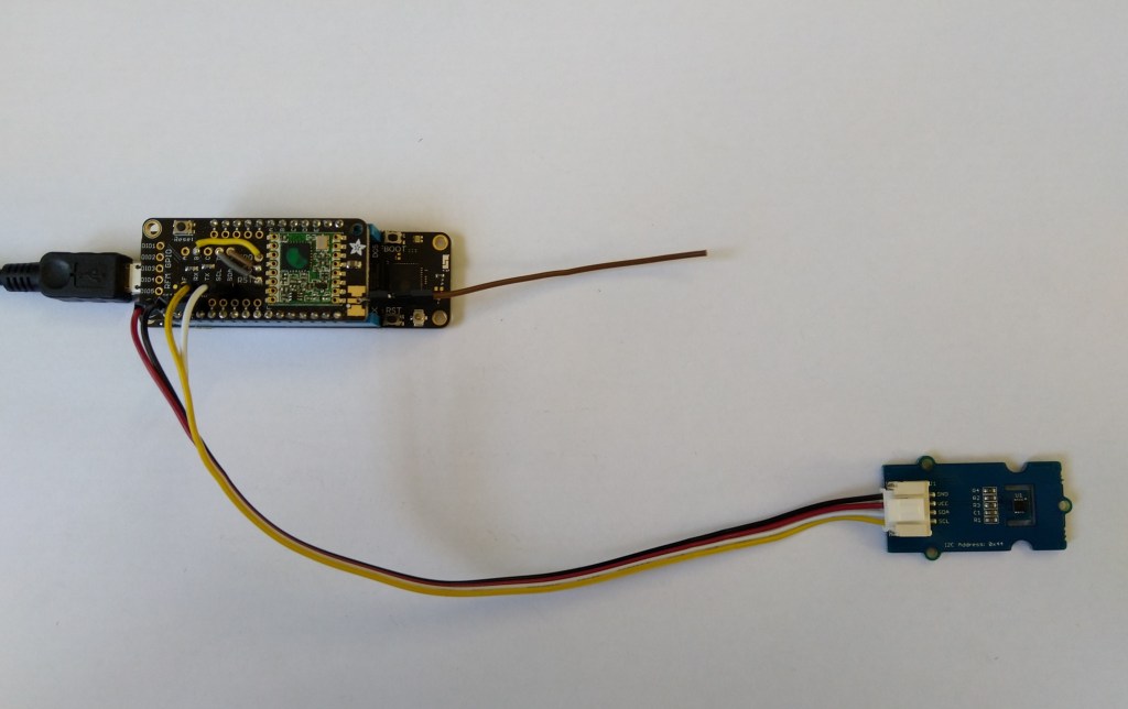
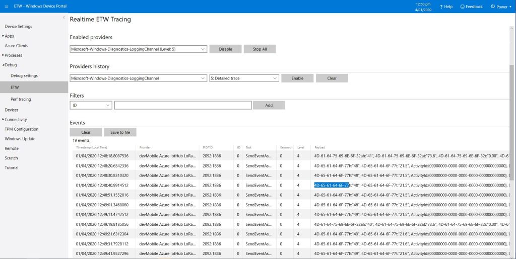
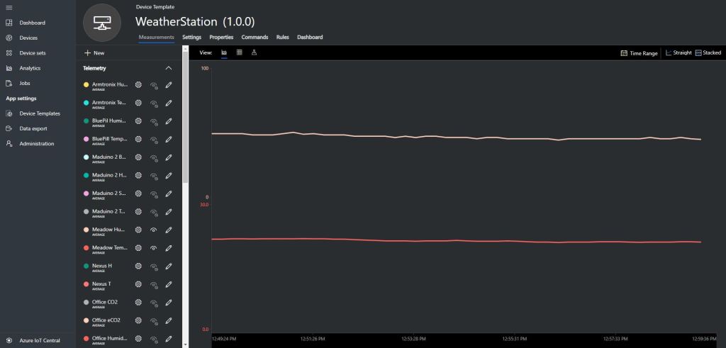
Meadow device with Seeedstudio SHT31 temperature & humidity sensorMeadow sensor data in Field Gateway ETW loggingMeadow Sensor data in Azure IoT Central
After a month or so of posts the source code of V1.0 of my Wilderness LabsMeadowRFM9X/SX127X library is on GitHub. I included all of the source for my test harness and proof of concept(PoC) application so other people can follow along with “my meadow learning experience”.
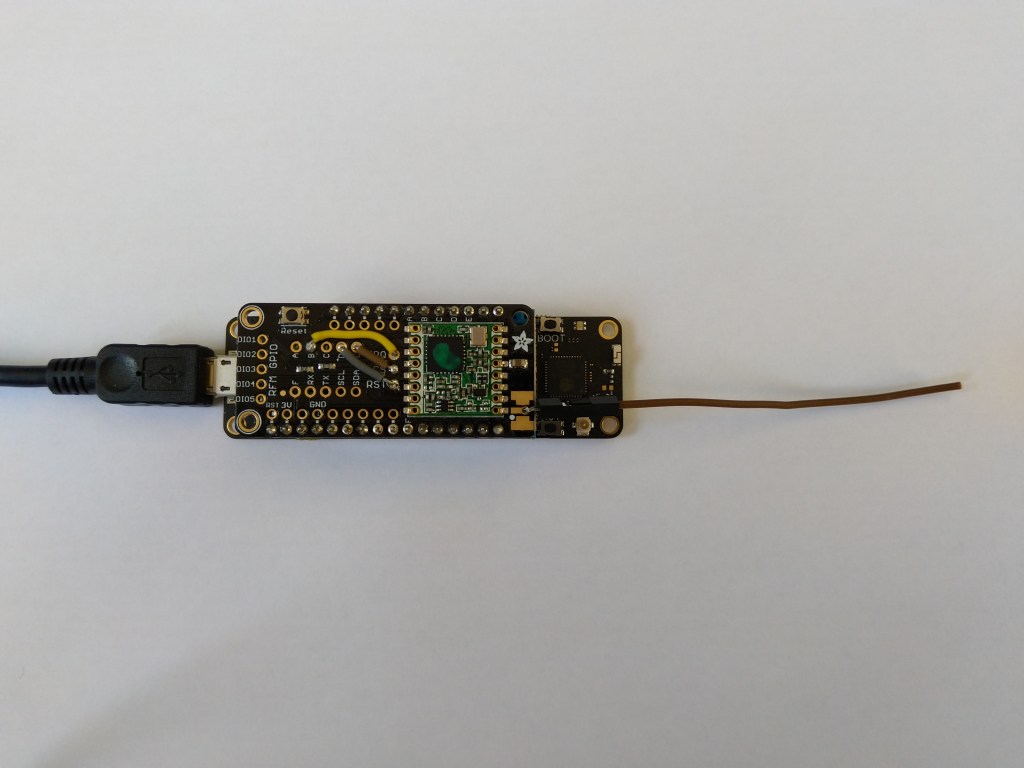
I initially started with a DraginoLoRa Shield for Arduino and jumper cables. I did this so only the pins I was using on the shield were connected to the Meadow.
Dragino LoRa Shield for Arduino based test harness
After problems with interleaved interrupt handling in my Windows 10 IoT Core client I figured the AutoMode used by the plainRFM69 library might be worth investigation. My first Arduino client was based on the plainRFM69 library but had Interoperability issues.
For this attempt I also started with the minimal sample and modified the code to send and receive text messages.
/*
    Copyright (c) 2014, Ivor Wanders, Bryn Lewis 2019
    MIT License, see the LICENSE.md file in the root folder.
*/

#include <SPI.h>
#include <plainRFM69.h>

// slave select pin.
#define SLAVE_SELECT_PIN 10

// connected to the reset pin of the RFM69.
#define RESET_PIN 9

// tie this pin down on the receiver.
#define SENDER_DETECT_PIN A0

const uint8_t tx_buffer[] = "ABCDEFGHIJKLMNOPQRSTURWXYZ1234567890";
//const uint8_t tx_buffer[] = "abcdefghijklmnopqrstuvwxyz1234567890";
uint8_t rx_buffer[sizeof(tx_buffer)] = "";

plainRFM69 rfm = plainRFM69(SLAVE_SELECT_PIN);


void sender() {

  uint32_t start_time = millis();

  uint32_t counter = 1; // the counter which we are going to send.

  while (true) {
    rfm.poll(); // run poll as often as possible.

    if (!rfm.canSend()) {
      continue; // sending is not possible, already sending.
    }

    if ((millis() - start_time) > 1000) { // every 500 ms.
      start_time = millis();

      // be a little bit verbose.
      Serial.print("Send:"); Serial.println(counter);

      // send the number of bytes equal to that set with setPacketLength.
      // read those bytes from memory where counter starts.
      rfm.sendVariable(tx_buffer, counter);

      counter++; // increase the counter.

      if ( counter > strlen(tx_buffer))
      {
        counter = 1;
      }
    }
  }
}

void receiver() {
  uint32_t counter = 0; // to count the messages.

  while (true) {

    rfm.poll(); // poll as often as possible.

    while (rfm.available())
    {
      uint8_t len = rfm.read(rx_buffer); // read the packet into the new_counter.

      // print verbose output.
      Serial.print("Packet Len:");
      Serial.print( len );
      Serial.print(" : ");
      Serial.println((char*)rx_buffer);
    }
  }
}

void setup() {
  Serial.begin(9600);
  SPI.begin();

  bareRFM69::reset(RESET_PIN); // sent the RFM69 a hard-reset.

  //rfm.setRecommended(); // set recommended paramters in RFM69.
  rfm.setPacketType(true, false); // set the used packet type.

  rfm.setBufferSize(2);   // set the internal buffer size.
  rfm.setPacketLength(sizeof(rx_buffer)); // set the packet length.

  rfm.setFrequency((uint32_t)909560000); // set the frequency.

  rfm.setLNA(RFM69_LNA_IMP_200OHM, RFM69_LNA_GAIN_AGC_LOOP);

  // p71, 3 preamble bytes.
  rfm.setPreambleSize(16);

  // p71, 4 bytes sync of 0x01, only start listening when sync is matched.
  //uint8_t syncthing[] = {0xaa, 0x2d, 0xd4};
  uint8_t syncthing[] = {0xd4, 0x2d, 0xaa};
  rfm.setSyncConfig(true, false, sizeof(syncthing), 0);
  rfm.setSyncValue(&syncthing, sizeof(syncthing));

  rfm.dumpRegisters(Serial);

  // baudrate is default, 4800 bps now.

  rfm.receive();
  // set it to receiving mode.

  pinMode(SENDER_DETECT_PIN, INPUT_PULLUP);
  delay(5);
}

void loop() {
  if (digitalRead(SENDER_DETECT_PIN) == LOW) {
    Serial.println("Going Receiver!");
    receiver();
    // this function never returns and contains an infinite loop.
  } else {
    Serial.println("Going sender!");
    sender();
    // idem.
  }
}
I took the list register values and loaded them into a Excel spreadsheet alongside the values from my Windows 10 IoT Core application
First thing I noticed was the order of the three sync byes (Registers 0x2F, 0x30, 0x31) was reversed. I then modified the run method in the Windows 10 code so the registers settings on both devices matched. (I removed the PlainRFM69 SetRecommended call so as many of the default options as possible were used).
I also found an error with the declaration of the RegPacketConfig1DcFree enumeration (Whitening = 0b0100000 vs. Whitening = 0b01000000) which wouldn’t have helped.
Register 0x4c - Value 0X00 - Bits 00000000
Register 0x4d - Value 0X00 - Bits 00000000
...
17:55:53.559 Received 1 byte message A CRC Ok True
.17:55:54.441 Received 2 byte message AB CRC Ok True
.17:55:55.444 Received 3 byte message ABC CRC Ok True
.17:55:56.447 Received 4 byte message ABCD CRC Ok True
.17:55:57.449 Received 5 byte message ABCDE CRC Ok True
.17:55:58.453 Received 6 byte message ABCDEF CRC Ok True
The thread 0x578 has exited with code 0 (0x0).
.17:55:59.622 Received 7 byte message ABCDEFG CRC Ok True
.17:56:00.457 Received 8 byte message ABCDEFGH CRC Ok True
.17:56:01.460 Received 9 byte message ABCDEFGHI CRC Ok True
.17:56:02.463 Received 10 byte message ABCDEFGHIJ CRC Ok True
..17:56:03.955 Received 11 byte message ABCDEFGHIJK CRC Ok True
17:56:04.583 Received 12 byte message ABCDEFGHIJKL CRC Ok True
I did some investigation into that the plainRMF69 code and found the ReadMultiple and WriteMuliple methods reverse the byte order
void bareRFM69::writeMultiple(uint8_t reg, void* data, uint8_t len){
    SPI.beginTransaction(SPISettings(10000000, MSBFIRST, SPI_MODE0));  // gain control of SPI bus
    this->chipSelect(true); // assert chip select
    SPI.transfer(RFM69_WRITE_REG_MASK | (reg & RFM69_READ_REG_MASK));
    uint8_t* r = reinterpret_cast<uint8_t*>(data);
    for (uint8_t i=0; i < len ; i++){
        SPI.transfer(r[len - i - 1]);
    }
    this->chipSelect(false);// deassert chip select
    SPI.endTransaction();    // release the SPI bus
}

void bareRFM69::readMultiple(uint8_t reg, void* data, uint8_t len){
    SPI.beginTransaction(SPISettings(10000000, MSBFIRST, SPI_MODE0));  // gain control of SPI bus
    this->chipSelect(true); // assert chip select

    SPI.transfer((reg % RFM69_READ_REG_MASK));
    uint8_t* r = reinterpret_cast<uint8_t*>(data);
    for (uint8_t i=0; i < len ; i++){
        r[len - i - 1] = SPI.transfer(0);
    }
    this->chipSelect(false);// deassert chip select
    SPI.endTransaction();    // release the SPI bus
}
I won’t be able to use interrupt AutoMode clients with the EasySensors shields as the DIO2 pin is not connected but on the AdaFruit RFM69HCW Radio Bonnet 433MHz or 915MHz it is connected to GPIO24.
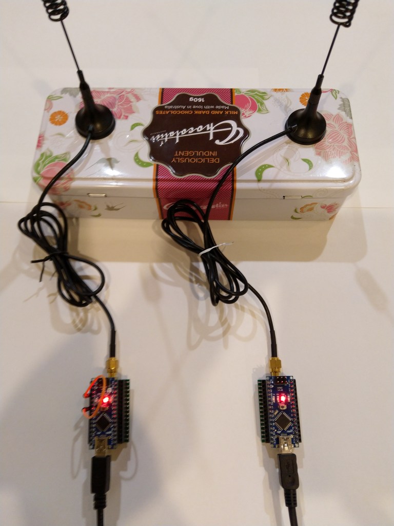
Every so often my Enums & Masks test harness locked up and stopped receiving messages from my test rig. This seemed to happen more often when the send functionality of my library was not being used.
easysensors RFM69HCW test rig
After 5 to 30 minutes (a couple of times it was 5 to 8 hours overnight) the application stopped receiving messages and wouldn’t resume until the application (device reset) was restarted or the RegOpmode-Mode was quickly changed to sleep then back to receive.
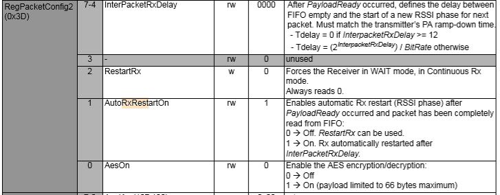
I had noticed this code in the Low Power Lab and wondered what it was for. The HopeRF library didn’t appear to have code like this to restart reception which was interesting.
void RFM69::send(uint16_t toAddress, const void* buffer, uint8_t bufferSize, bool requestACK)
{
  writeReg(REG_PACKETCONFIG2, (readReg(REG_PACKETCONFIG2) & 0xFB) | RF_PACKET2_RXRESTART); // avoid RX deadlocks
  uint32_t now = millis();
  while (!canSend() && millis() - now < RF69_CSMA_LIMIT_MS) receiveDone();
  sendFrame(toAddress, buffer, bufferSize, requestACK, false);
}

// should be called immediately after reception in case sender wants ACK
void RFM69::sendACK(const void* buffer, uint8_t bufferSize) {
  ACK_REQUESTED = 0;   // TWS added to make sure we don't end up in a timing race and infinite loop sending Acks
  uint16_t sender = SENDERID;
  int16_t _RSSI = RSSI; // save payload received RSSI value
  writeReg(REG_PACKETCONFIG2, (readReg(REG_PACKETCONFIG2) & 0xFB) | RF_PACKET2_RXRESTART); // avoid RX deadlocks
  uint32_t now = millis();
  while (!canSend() && millis() - now < RF69_CSMA_LIMIT_MS) receiveDone();
  SENDERID = sender;    // TWS: Restore SenderID after it gets wiped out by receiveDone()
  sendFrame(sender, buffer, bufferSize, false, true);
  RSSI = _RSSI; // restore payload RSSI
}

void RFM69::receiveBegin() {
  DATALEN = 0;
  SENDERID = 0;
  TARGETID = 0;
  PAYLOADLEN = 0;
  ACK_REQUESTED = 0;
  ACK_RECEIVED = 0;
#if defined(RF69_LISTENMODE_ENABLE)
  RF69_LISTEN_BURST_REMAINING_MS = 0;
#endif
  RSSI = 0;
  if (readReg(REG_IRQFLAGS2) & RF_IRQFLAGS2_PAYLOADREADY)
    writeReg(REG_PACKETCONFIG2, (readReg(REG_PACKETCONFIG2) & 0xFB) | RF_PACKET2_RXRESTART); // avoid RX deadlocks
  writeReg(REG_DIOMAPPING1, RF_DIOMAPPING1_DIO0_01); // set DIO0 to "PAYLOADREADY" in receive mode
  setMode(RF69_MODE_RX);
}
In the debug output you can see that clock frequencies of the two test devices are slightly different. Every so often they transmit close enough to corrupt one of the message payloads which causes the deadlock.
Sometimes while testing code you notice something odd. Every so often the Enums & Masks application locks up and stops receiving messages from my test rig.
easysensors RFM69HCW test rig
The symptom is that after 5 to 30 minutes the application stops receiving messages
21:37:37.568 RegIrqFlags1 11011001
21:37:37.583 Address 0X99 10011001
21:37:37 Received 14 byte message Hello World:61
..21:37:38.693 RegIrqFlags2 01100110
21:37:38.706 RegIrqFlags1 11011001
21:37:38.724 Address 0X99 10011001
21:37:38 Received 14 byte message Hello World:62
............The thread 0xba8 has exited with code 0 (0x0).
.................................................................................................................................................The thread 0xf90 has exited with code 0 (0x0).
.....................The thread 0xe30 has exited with code 0 (0x0).
.......................The thread 0xa04 has exited with code 0 (0x0).
................................The thread 0xc8c has exited with code 0 (0x0).
..........................................................................................The thread 0xc38 has exited with code 0 (0x0).
......................The thread 0xf68 has exited with code 0 (0x0).
......................................................................................The thread 0x1c8 has exited with code 0 (0x0).
..........The thread 0xeb8 has exited with code 0 (0x0).
..............................................................The thread 0xbb8 has exited with code 0 (0x0).
..........The thread 0xdc0 has exited with code 0 (0x0).
...............................The thread 0x820 has exited with code 0 (0x0).
....................................The thread 0xaac has exited with code 0 (0x0).
......The thread 0xbf0 has exited with code 0 (0x0).
............................................The thread 0x4e8 has exited with code 0 (0x0).
...............................The thread 0x1b4 has exited with code 0 (0x0).
...............................................................The thread 0xbdc has exited with code 0 (0x0).
....................The thread 0xb60 has exited with code 0 (0x0).
.........................................................................................................The thread 0x510 has exited with code 0 (0x0).
........The thread 0xf60 has exited with code 0 (0x0).
........................................................The thread 0x3c0 has exited with code 0 (0x0).
......................................The thread 0xa4c has exited with code 0 (0x0).
..................................................................The thread 0x9e0 has exited with code 0 (0x0).
....................The thread 0xd74 has exited with code 0 (0x0).
............................The thread 0xfa0 has exited with code 0 (0x0).
..................................................................................................The thread 0xfe0 has exited with code 0 (0x0).
....................................................................................The thread 0xdd4 has exited with code 0 (0x0).
........................The thread 0xc00 has exited with code 0 (0x0).
..................................The thread 0x478 has exited with code 0 (0x0).
.........................The thread 0x88c has exited with code 0 (0x0).
...........................................The thread 0x280 has exited with code 0 (0x0).
..........................................The thread 0x8e4 has exited with code 0 (0x0).
............The thread 0x410 has exited with code 0 (0x0).
..............................................The thread 0xa70 has exited with code 0 (0x0).
................The thread 0x994 has exited with code 0 (0x0).
....................The thread 0x298 has exited with code 0 (0x0).
..............The thread 0x3a4 has exited with code 0 (0x0).
............................................................The thread 0xa2c has exited with code 0 (0x0).
..........The thread 0x208 has exited with code 0 (0x0).
..........................................................................The thread 0xbd4 has exited with code 0 (0x0).
............The thread 0xfdc has exited with code 0 (0x0).
........................................................................The thread 0x36c has exited with code 0 (0x0).
...........22:08:57.638 RegIrqFlags2 01100110
22:08:57.658 RegIrqFlags1 11011001
22:08:57.676 Address 0X66 01100110
22:08:57 Received 15 byte message Hello World:157
22:08:57.807 RegIrqFlags2 01100110
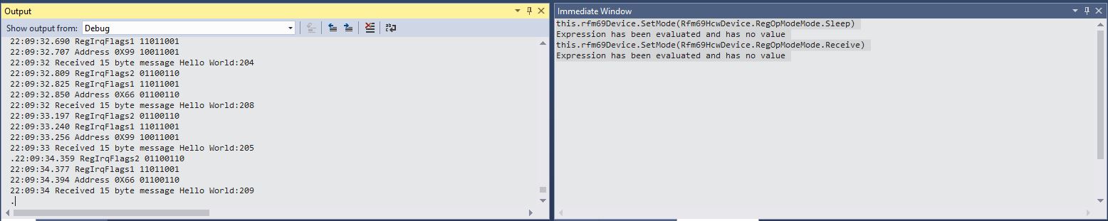
But, every so often it would after many minutes start up again without me doing anything (I noticed this after leaving application running overnight). I could get the application to restart by putting a break point on the Debug.Write(“.”) and toggling the OperationMode from Sleep to Receive
Using Visual Studio Immediate Windows to execute SetMode
I have found if the device is transmitting every so often the lockups are also much less likely. To help with debugging the issue I have wired up the three buttons on the Adafruit Radio Bonnet to call different diagnostic code
Looks like this maybe a bit of a heisenbug as it takes a longish time to appear and poking around in the debugger and adding more diagnostics changes the frequency the error.
Received 16 byte message
Receive-Done
.............................Receive-No wait
Received 16 byte message
Receive-Done
Receive-No wait
Received 16 byte message
Receive-Done
....Receive-No wait
Received 16 byte message
Receive-Done
Receive-No wait
Received 16 byte message
Receive-Done
.............
Pressing button one restarts inbound messages for a while, button two sits in an endless loop, button three reads in a 16 byte message of 0x10 characters, which I think is buffer length. I have added code to catch exceptions and stop re-entrancy but it never seems to get triggered.
Based on the approach I used in my RFM9X library this refactor adds enumerations and constants for initialising and then accessing the registers of the RFM69CW/RFM69HCW module (based on the Semtech SX1231/SX1231H) .
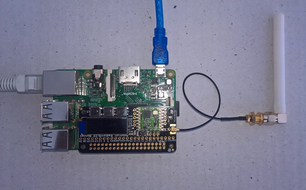
Adafruit RFM69 Radio Bonnet
There is now a even less code in the Run method in the startup.cs file and the code for configuring the RFM69 is more obvious
The Rasmitic library modifies a number of the default settings (e.g. RegRxBw register) so I had to reverse engineer the values. I also added SendMessage methods for both addressed and un-addressed messages.
Register dump
Register 0x01 - Value 0X04 - Bits 00000100
Register 0x02 - Value 0X00 - Bits 00000000
Register 0x03 - Value 0X1a - Bits 00011010
…
Register 0x4b - Value 0X00 - Bits 00000000
Register 0x4c - Value 0X00 - Bits 00000000
Register 0x4d - Value 0X00 - Bits 00000000
16:52:38.337 Send-Done
16:52:38.456 RegIrqFlags 00001000
16:52:38.472 Transmit-Done
The thread 0xfe4 has exited with code 0 (0x0).
The thread 0x100 has exited with code 0 (0x0).
16:52:43.391 Send-Done
16:52:43.465 RegIrqFlags 00001000
16:52:43.480 Transmit-Done
The thread 0xb94 has exited with code 0 (0x0).
16:52:48.475 Send-Done
16:52:48.550 RegIrqFlags 00001000
16:52:48.563 Transmit-Done
16:52:53.448 RegIrqFlags 01000110
16:52:53 Received 13 byte message Hello world:0
The thread 0x2b4 has exited with code 0 (0x0).
16:52:53.559 Send-Done
16:52:53.633 RegIrqFlags 00001000
16:52:53.648 Transmit-Done
16:52:54.577 RegIrqFlags 01000110
16:52:54 Received 13 byte message Hello world:1
16:52:55.706 RegIrqFlags 01000110
16:52:55 Received 13 byte message Hello world:2
16:52:56.836 RegIrqFlags 01000110
16:52:56 Received 13 byte message Hello world:3
16:52:57.965 RegIrqFlags 01000110
16:52:57 Received 13 byte message Hello world:4
The thread 0x354 has exited with code 0 (0x0).
16:52:58.634 Send-Done
16:52:58.709 RegIrqFlags 00001000
16:52:58.724 Transmit-Done
16:52:59.095 RegIrqFlags 01000110
16:52:59 Received 13 byte message Hello world:5
The program '[3736] backgroundTaskHost.exe' has exited with code -1
The Arduino code works though I need modify it so I can do more testing of the initialise method parameter options.
Most of the initialise method follows a similar pattern, checking parameters associated with a Register and only setting it if the cvalues are not all the default
I have just got to finish the code for RegFifoThresh, RegPacketConfig2 and the RegAesKey1-16 registers.
Other libraries for the RRFM69 support changing configuration while the application is running which significantly increases the complexity and number of test cases. My initial version will only support configuration on start-up.
I had been meaning to refactor the code for accessing the registers of the RFM69CW/RFM69HCW module (based on the Semtech SX1231/SX1231H) registers for a while.
Adafruit RFM69 Radio Bonnet
There is now a lot less code in the startup.cs file and the code for configuring the RFM69 is more obvious
/*
    Copyright ® 2019 July devMobile Software, All Rights Reserved

	 MIT License

	 Permission is hereby granted, free of charge, to any person obtaining a copy
	 of this software and associated documentation files (the "Software"), to deal
    in the Software without restriction, including without limitation the rights
	 to use, copy, modify, merge, publish, distribute, sublicense, and/or sell
	 copies of the Software, and to permit persons to whom the Software is
    furnished to do so, subject to the following conditions:

    The above copyright notice and this permission notice shall be included in all
	 copies or substantial portions of the Software.

    THE SOFTWARE IS PROVIDED "AS IS", WITHOUT WARRANTY OF ANY KIND, EXPRESS OR
	 IMPLIED, INCLUDING BUT NOT LIMITED TO THE WARRANTIES OF MERCHANTABILITY,
    FITNESS FOR A PARTICULAR PURPOSE AND NONINFRINGEMENT. IN NO EVENT SHALL THE
	 AUTHORS OR COPYRIGHT HOLDERS BE LIABLE FOR ANY CLAIM, DAMAGES OR OTHER
	 LIABILITY, WHETHER IN AN ACTION OF CONTRACT, TORT OR OTHERWISE, ARISING FROM,
    OUT OF OR IN CONNECTION WITH THE SOFTWARE OR THE USE OR OTHER DEALINGS IN THE
	 SOFTWARE

 */
namespace devMobile.IoT.Rfm69Hcw.RefactorRegisterManager
{
	using System;
	using System.Diagnostics;
	using System.Text;
	using System.Threading.Tasks;
	using Windows.ApplicationModel.Background;
	using Windows.Devices.Gpio;

	sealed class Rfm69HcwDevice
	{
		private GpioPin InterruptGpioPin = null;
		public RegisterManager RegisterManager = null; // Future refactor this will be made private

		public Rfm69HcwDevice(ChipSelectPin chipSelectPin, int resetPin, int interruptPin)
		{
			RegisterManager = new RegisterManager(chipSelectPin);

			// Factory reset pin configuration
			GpioController gpioController = GpioController.GetDefault();
			GpioPin resetGpioPin = gpioController.OpenPin(resetPin);
			resetGpioPin.SetDriveMode(GpioPinDriveMode.Output);
			resetGpioPin.Write(GpioPinValue.High);
			Task.Delay(100);
			resetGpioPin.Write(GpioPinValue.Low);
			Task.Delay(10);

			// Interrupt pin for RX message & TX done notification
			InterruptGpioPin = gpioController.OpenPin(interruptPin);
			resetGpioPin.SetDriveMode(GpioPinDriveMode.Input);

			InterruptGpioPin.ValueChanged += InterruptGpioPin_ValueChanged;
		}

		private void InterruptGpioPin_ValueChanged(GpioPin sender, GpioPinValueChangedEventArgs args)
		{
			if (args.Edge != GpioPinEdge.RisingEdge)
			{
				return;
			}

			byte irqFlags = RegisterManager.ReadByte(0x28); // RegIrqFlags2
			Debug.WriteLine("{0:HH:mm:ss.fff} RegIrqFlags {1}", DateTime.Now, Convert.ToString((byte)irqFlags, 2).PadLeft(8, '0'));
			if ((irqFlags & 0b00000100) == 0b00000100)  // PayLoadReady set
			{
				// Read the length of the buffer
				byte numberOfBytes = RegisterManager.ReadByte(0x0);

				// Allocate buffer for message
				byte[] messageBytes = new byte[numberOfBytes];

				for (int i = 0; i < numberOfBytes; i++)
				{
					messageBytes[i] = RegisterManager.ReadByte(0x00); // RegFifo
				}

				string messageText = UTF8Encoding.UTF8.GetString(messageBytes);
				Debug.WriteLine("{0:HH:mm:ss} Received {1} byte message {2}", DateTime.Now, messageBytes.Length, messageText);
			}

			if ((irqFlags & 0b00001000) == 0b00001000)  // PacketSent set
			{
				RegisterManager.WriteByte(0x01, 0b00010000); // RegOpMode set ReceiveMode
				Debug.WriteLine("{0:HH:mm:ss.fff} Transmit-Done", DateTime.Now);
			}
		}

		public void RegisterDump()
		{
			RegisterManager.Dump(0x0, 0x40);
		}
	}


	public sealed class StartupTask : IBackgroundTask
	{
		private const int ResetPin = 25;
		private const int InterruptPin = 22;
		private Rfm69HcwDevice rfm69Device = new Rfm69HcwDevice(ChipSelectPin.CS1, ResetPin, InterruptPin);

		const double RH_RF6M9HCW_FXOSC = 32000000.0;
		const double RH_RFM69HCW_FSTEP = RH_RF6M9HCW_FXOSC / 524288.0;

		public void Run(IBackgroundTaskInstance taskInstance)
		{
			//rfm69Device.RegisterDump();

			// regOpMode standby
			rfm69Device.RegisterManager.WriteByte(0x01, 0b00000100);

			// BitRate MSB/LSB
			rfm69Device.RegisterManager.WriteByte(0x03, 0x34);
			rfm69Device.RegisterManager.WriteByte(0x04, 0x00);

			// Frequency deviation
			rfm69Device.RegisterManager.WriteByte(0x05, 0x02);
			rfm69Device.RegisterManager.WriteByte(0x06, 0x3d);

			// Calculate the frequency accoring to the datasheett
			byte[] bytes = BitConverter.GetBytes((uint)(915000000.0 / RH_RFM69HCW_FSTEP));
			Debug.WriteLine("Byte Hex 0x{0:x2} 0x{1:x2} 0x{2:x2} 0x{3:x2}", bytes[0], bytes[1], bytes[2], bytes[3]);
			rfm69Device.RegisterManager.WriteByte(0x07, bytes[2]);
			rfm69Device.RegisterManager.WriteByte(0x08, bytes[1]);
			rfm69Device.RegisterManager.WriteByte(0x09, bytes[0]);

			// RegRxBW
			rfm69Device.RegisterManager.WriteByte(0x19, 0x2a);

			// RegDioMapping1
			rfm69Device.RegisterManager.WriteByte(0x26, 0x01);

			// Setup preamble length to 16 (default is 3) RegPreambleMsb RegPreambleLsb
			rfm69Device.RegisterManager.WriteByte(0x2C, 0x0);
			rfm69Device.RegisterManager.WriteByte(0x2D, 0x10);

			// RegSyncConfig Set the Sync length and byte values SyncOn + 3 custom sync bytes
			rfm69Device.RegisterManager.WriteByte(0x2e, 0x90);

			// RegSyncValues1 thru RegSyncValues3
			rfm69Device.RegisterManager.WriteByte(0x2f, 0xAA);
			rfm69Device.RegisterManager.WriteByte(0x30, 0x2D);
			rfm69Device.RegisterManager.WriteByte(0x31, 0xD4);

			// RegPacketConfig1 Variable length with CRC on
			rfm69Device.RegisterManager.WriteByte(0x37, 0x90);

			rfm69Device.RegisterDump();

			while (true)
			{
				// Standby mode while loading message into FIFO
				rfm69Device.RegisterManager.WriteByte(0x01, 0b00000100);

				byte[] messageBuffer = UTF8Encoding.UTF8.GetBytes("hello world " + DateTime.Now.ToLongTimeString());
				rfm69Device.RegisterManager.WriteByte(0x0, (byte)messageBuffer.Length);
				rfm69Device.RegisterManager.Write(0x0, messageBuffer);

				// Transmit mode once FIFO loaded
				rfm69Device.RegisterManager.WriteByte(0x01, 0b00001100);

				Debug.WriteLine("{0:HH:mm:ss.fff} Send-Done", DateTime.Now);

				Task.Delay(5000).Wait();
			}
		}
	}
}
I’ll modify the constructor reset pin support to see if I can get the Seegel Systeme hat working.
Register dump
Register 0x00 - Value 0X00 - Bits 00000000
Register 0x01 - Value 0X04 - Bits 00000100
Register 0x02 - Value 0X00 - Bits 00000000
Register 0x03 - Value 0X34 - Bits 00110100
…
Register 0x3e - Value 0X00 - Bits 00000000
Register 0x3f - Value 0X00 - Bits 00000000
Register 0x40 - Value 0X00 - Bits 00000000
19:58:52.828 Send-Done
19:58:53.022 RegIrqFlags 00001000
19:58:53.036 Transmit-Done
19:58:54.188 RegIrqFlags 01000110
19:58:54 Received 14 byte message Hello world:1
The thread 0xa10 has exited with code 0 (0x0).
The thread 0xf90 has exited with code 0 (0x0).
19:58:57.652 RegIrqFlags 01000110
19:58:57 Received 14 byte message Hello world:2
19:58:57.892 Send-Done
19:58:58.039 RegIrqFlags 00001000
19:58:58.053 Transmit-Done
19:59:01.115 RegIrqFlags 01000110
19:59:01 Received 14 byte message Hello world:3
19:59:02.936 Send-Done
19:59:03.083 RegIrqFlags 00001000
19:59:03.096 Transmit-Done
19:59:04.577 RegIrqFlags 01000110
19:59:04 Received 14 byte message Hello world:4
The thread 0xa5c has exited with code 0 (0x0).
19:59:08.001 Send-Done
19:59:08.122 RegIrqFlags 01001000
19:59:08.139 Transmit-Done
19:59:11.504 RegIrqFlags 01000110
19:59:11 Received 14 byte message Hello world:6
The thread 0xb18 has exited with code 0 (0x0).
19:59:13.079 Send-Done
19:59:13.226 RegIrqFlags 00001000
19:59:13.240 Transmit-Done
19:59:14.966 RegIrqFlags 01000110
19:59:14 Received 14 byte message Hello world:7
Based how my rate of progress improved when I did this on the RFM9X library I really should have done this much earlier.
In the Arduino code I found the order of initialisation was critical. Because of the way the Rasmatic library is written the call to vRF69SetAesKey has to be after the vInitialize.
The next step will be merging and refactoring the test harness to extract the code for accessing the RFM69 registers into a separate class, then defining enumerations and constants for all the RFM69 settings.
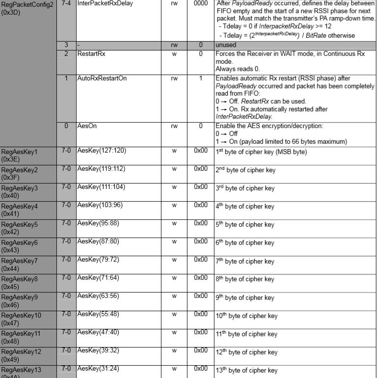
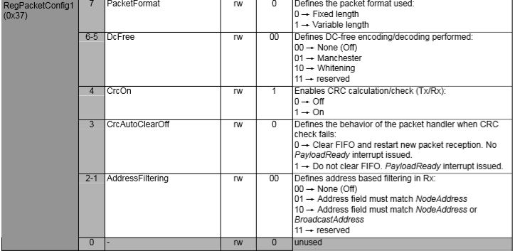
The RFM69CW/RFM69HCW modules (based on the Semtech SX1231/SX1231H) have built in support for addressing individual devices (register RegNodeAdrs 0x39) or broadcasting to groups of devices (register RegBroadcastAdrs 0x3A). In this test harness I’m exploring the RFM69 device support for these two different addressing modes which is configured in RegPacketConfig1 0x37.
RFM69 Address filtering options
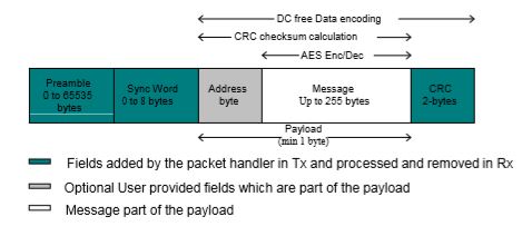
The fixed length packet format contains the following fields
Preamble (1010…)
Sync word (Network ID)
Optional Address byte (Node ID)
Message data
Optional 2-bytes CRC checksum
Fixed length packet format
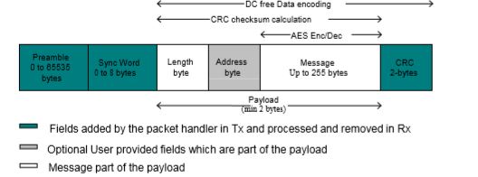
The variable length packet format contains the following fields
Preamble (1010…)
Sync word (Network ID)
Length byte
Optional Address byte (Node ID)
Message data
Optional 2-bytes CRC checksum
Variable length packet format
My first attempt at addressing was by modifying the payload (the extra space at the start of the payload was replaced by the target device address)
Initially it truncated messages because I neglected to include the byte with the length of the message in the length of the message. I also had to extend the timeout for sending a message a bit more than I expected for one extra byte.
bool RMRFM69::bSendMessage(byte address, byte msg[], byte length)
{
byte tmp;
 uint32_t overtime;
 word bittime;

 switch(COB)
	{
	case RFM65:									//only for Rx
	case RFM65C:
		return(false);
	case RFM69H:
	case RFM69HC:
 		vSpiWrite(((word)RegTestPa1<<8)+0x5D);		//for HighPower
	 	vSpiWrite(((word)RegTestPa2<<8)+0x7C);
		break;
	default:
	case RFM69:
	case RFM69C:
	 	vSpiWrite(((word)RegTestPa1<<8)+0x55);		//for NormalMode or RxMode
 		vSpiWrite(((word)RegTestPa2<<8)+0x70);
		break;
	}

 vSpiWrite(((word)RegDioMapping1<<8)+0x04);	//DIO0 PacketSend  / DIO1 FiflLevel / DIO2 Data /DIO3 FifoFull

 if(!FixedPktLength)
 	vSpiWrite(((word)RegFifo<<8)+length+1);
 vSpiWrite(((word)RegFifo<<8)+address);

 vSpiBurstWrite(RegFifo, msg, length);

 tmp = bSpiRead(RegOpMode);
 tmp&= MODE_MASK;
 tmp |= RADIO_TX;
 vSpiWrite(((word)RegOpMode<<8)+tmp);

 //�ȴ��������
 bittime  = SymbolTime/1000;		//unit: us
 overtime = SyncLength+PreambleLength+length+1;
 if(!FixedPktLength)				//SyncWord & PktLength & 2ByteCRC
    overtime += 1;
 if(!CrcDisable)
 	overtime += 2;
 overtime<<=3;					//8bit == 1byte
 overtime*= bittime;
 overtime/= 1000;				//unit: ms
 if(overtime==0)
 	overtime = 1;
 overtime += (overtime>>3);		//add 12.5% for ensure
 delay(overtime);			//
 for(tmp=0;tmp<1000;tmp++)		//about 50ms for overtime
 	{
 	if(digitalRead(_dio0Pin))
 		break;
 	delayMicroseconds(500);
 	}
 vGoStandby();
 if(tmp>=200)
 	return(false);
 else
 	return(true);
}
The Windows 10 IoT Core library interrupt handler needed some modification to display message only when the address matched and I also displayed the targeted address so I could check that device and broadcast addressing was working
/*
    Copyright ® 2019 July devMobile Software, All Rights Reserved

	 MIT License

	 Permission is hereby granted, free of charge, to any person obtaining a copy
	 of this software and associated documentation files (the "Software"), to deal
    in the Software without restriction, including without limitation the rights
	 to use, copy, modify, merge, publish, distribute, sublicense, and/or sell
	 copies of the Software, and to permit persons to whom the Software is
    furnished to do so, subject to the following conditions:

    The above copyright notice and this permission notice shall be included in all
	 copies or substantial portions of the Software.

    THE SOFTWARE IS PROVIDED "AS IS", WITHOUT WARRANTY OF ANY KIND, EXPRESS OR
	 IMPLIED, INCLUDING BUT NOT LIMITED TO THE WARRANTIES OF MERCHANTABILITY,
    FITNESS FOR A PARTICULAR PURPOSE AND NONINFRINGEMENT. IN NO EVENT SHALL THE
	 AUTHORS OR COPYRIGHT HOLDERS BE LIABLE FOR ANY CLAIM, DAMAGES OR OTHER
	 LIABILITY, WHETHER IN AN ACTION OF CONTRACT, TORT OR OTHERWISE, ARISING FROM,
    OUT OF OR IN CONNECTION WITH THE SOFTWARE OR THE USE OR OTHER DEALINGS IN THE
	 SOFTWARE

 */
namespace devMobile.IoT.Rfm69Hcw.Addressing
{
	using System;
	using System.Diagnostics;
	using System.Runtime.InteropServices.WindowsRuntime;
	using System.Text;
	using System.Threading.Tasks;
	using Windows.ApplicationModel.Background;
	using Windows.Devices.Gpio;
	using Windows.Devices.Spi;

	public sealed class Rfm69HcwDevice
	{
		private SpiDevice Rfm69Hcw;
		private GpioPin InterruptGpioPin = null;
		private const byte RegisterAddressReadMask = 0X7f;
		private const byte RegisterAddressWriteMask = 0x80;

		public Rfm69HcwDevice(int chipSelectPin, int resetPin, int interruptPin)
		{
			SpiController spiController = SpiController.GetDefaultAsync().AsTask().GetAwaiter().GetResult();
			var settings = new SpiConnectionSettings(chipSelectPin)
			{
				ClockFrequency = 500000,
				Mode = SpiMode.Mode0,
			};

			// Factory reset pin configuration
			GpioController gpioController = GpioController.GetDefault();
			GpioPin resetGpioPin = gpioController.OpenPin(resetPin);
			resetGpioPin.SetDriveMode(GpioPinDriveMode.Output);
			resetGpioPin.Write(GpioPinValue.High);
			Task.Delay(100);
			resetGpioPin.Write(GpioPinValue.Low);
			Task.Delay(10);

			// Interrupt pin for RX message & TX done notification
			InterruptGpioPin = gpioController.OpenPin(interruptPin);
			resetGpioPin.SetDriveMode(GpioPinDriveMode.Input);

			InterruptGpioPin.ValueChanged += InterruptGpioPin_ValueChanged;

			Rfm69Hcw = spiController.GetDevice(settings);
		}

		private void InterruptGpioPin_ValueChanged(GpioPin sender, GpioPinValueChangedEventArgs args)
		{
			if (args.Edge != GpioPinEdge.RisingEdge)
			{
				return;
			}

			byte irqFlags2 = this.RegisterReadByte(0x28); // RegIrqFlags2
			Debug.WriteLine("{0:HH:mm:ss.fff} RegIrqFlags2 {1}", DateTime.Now, Convert.ToString((byte)irqFlags2, 2).PadLeft(8, '0'));
			if ((irqFlags2 & 0b00000100) == 0b00000100)  // PayLoadReady set
			{
				byte irqFlags1 = this.RegisterReadByte(0x27); // RegIrqFlags1

				// Read the length of the buffer
				byte numberOfBytes = this.RegisterReadByte(0x0);

				Debug.WriteLine("{0:HH:mm:ss.fff} RegIrqFlags1 {1}", DateTime.Now, Convert.ToString((byte)irqFlags1, 2).PadLeft(8, '0'));
				if ((irqFlags1 & 0b00000001) == 0b00000001)  // SyncAddressMatch
				{
					byte address = this.RegisterReadByte(0x0);
					Debug.WriteLine("{0:HH:mm:ss.fff} Address 0X{1:X2} b{2}", DateTime.Now, address, Convert.ToString((byte)address, 2).PadLeft(8, '0'));
					numberOfBytes--;
				}

				// Allocate buffer for message
				byte[] messageBytes = new byte[numberOfBytes];

				for (int i = 0; i < numberOfBytes; i++)
				{
					messageBytes[i] = this.RegisterReadByte(0x00); // RegFifo
				}

				string messageText = UTF8Encoding.UTF8.GetString(messageBytes);
				Debug.WriteLine("{0:HH:mm:ss} Received:{1} byte message({2})", DateTime.Now, messageBytes.Length, messageText);
			}

			if ((irqFlags2 & 0b00001000) == 0b00001000)  // PacketSent set
			{
				this.RegisterWriteByte(0x01, 0b00010000); // RegOpMode set ReceiveMode
				Debug.WriteLine("{0:HH:mm:ss.fff} Transmit-Done", DateTime.Now);
			}
		}

		public Byte RegisterReadByte(byte address)
		{
			byte[] writeBuffer = new byte[] { address &= RegisterAddressReadMask };
			byte[] readBuffer = new byte[1];
			Debug.Assert(Rfm69Hcw != null);

			Rfm69Hcw.TransferSequential(writeBuffer, readBuffer);

			return readBuffer[0];
		}

		public byte[] RegisterRead(byte address, int length)
		{
			byte[] writeBuffer = new byte[] { address &= RegisterAddressReadMask };
			byte[] readBuffer = new byte[length];
			Debug.Assert(Rfm69Hcw != null);

			Rfm69Hcw.TransferSequential(writeBuffer, readBuffer);

			return readBuffer;
		}

		public void RegisterWriteByte(byte address, byte value)
		{
			byte[] writeBuffer = new byte[] { address |= RegisterAddressWriteMask, value };
			Debug.Assert(Rfm69Hcw != null);

			Rfm69Hcw.Write(writeBuffer);
		}

		public void RegisterWrite(byte address, [ReadOnlyArray()] byte[] bytes)
		{
			byte[] writeBuffer = new byte[1 + bytes.Length];
			Debug.Assert(Rfm69Hcw != null);

			Array.Copy(bytes, 0, writeBuffer, 1, bytes.Length);
			writeBuffer[0] = address |= RegisterAddressWriteMask;

			Rfm69Hcw.Write(writeBuffer);
		}

		public void RegisterDump()
		{
			Debug.WriteLine("Register dump");
			for (byte registerIndex = 0; registerIndex <= 0x3D; registerIndex++)
			{
				byte registerValue = this.RegisterReadByte(registerIndex);

				Debug.WriteLine("Register 0x{0:x2} - Value 0X{1:x2} - Bits {2}", registerIndex, registerValue, Convert.ToString(registerValue, 2).PadLeft(8, '0'));
			}
		}
	}

	public sealed class StartupTask : IBackgroundTask
	{
		private const int ChipSelectLine = 1;
		private const int ResetPin = 25;
		private const int InterruptPin = 22;
		private Rfm69HcwDevice rfm69Device = new Rfm69HcwDevice(ChipSelectLine, ResetPin, InterruptPin);

		const double RH_RF6M9HCW_FXOSC = 32000000.0;
		const double RH_RFM69HCW_FSTEP = RH_RF6M9HCW_FXOSC / 524288.0;

		public void Run(IBackgroundTaskInstance taskInstance)
		{
			//rfm69Device.RegisterDump();

			// regOpMode standby
			rfm69Device.RegisterWriteByte(0x01, 0b00000100);

			// BitRate MSB/LSB
			rfm69Device.RegisterWriteByte(0x03, 0x34);
			rfm69Device.RegisterWriteByte(0x04, 0x00);

			// Frequency deviation
			rfm69Device.RegisterWriteByte(0x05, 0x02);
			rfm69Device.RegisterWriteByte(0x06, 0x3d);

			// Calculate the frequency accoring to the datasheett
			byte[] bytes = BitConverter.GetBytes((uint)(915000000.0 / RH_RFM69HCW_FSTEP));
			Debug.WriteLine("Byte Hex 0x{0:x2} 0x{1:x2} 0x{2:x2} 0x{3:x2}", bytes[0], bytes[1], bytes[2], bytes[3]);
			rfm69Device.RegisterWriteByte(0x07, bytes[2]);
			rfm69Device.RegisterWriteByte(0x08, bytes[1]);
			rfm69Device.RegisterWriteByte(0x09, bytes[0]);

			// RegRxBW
			rfm69Device.RegisterWriteByte(0x19, 0x2a);

			// RegDioMapping1
			rfm69Device.RegisterWriteByte(0x26, 0x01);

			// Setup preamble length to 16 (default is 3) RegPreambleMsb RegPreambleLsb
			rfm69Device.RegisterWriteByte(0x2C, 0x0);
			rfm69Device.RegisterWriteByte(0x2D, 0x10);

			// RegSyncConfig Set the Sync length and byte values SyncOn + 3 custom sync bytes
			rfm69Device.RegisterWriteByte(0x2e, 0x90);

			// RegSyncValues1 thru RegSyncValues3
			rfm69Device.RegisterWriteByte(0x2f, 0xAA);
			rfm69Device.RegisterWriteByte(0x30, 0x2D);
			rfm69Device.RegisterWriteByte(0x31, 0xD4);

			// RegPacketConfig1 Variable length with CRC on
			//rfm69Device.RegisterWriteByte(0x37, 0x90);

			// RegPacketConfig1 Variable length with CRC on + NodeAddress
			//rfm69Device.RegisterWriteByte(0x37, 0x92);

			// RegPacketConfig1 Variable length with CRC on + NodeAddress & Broadcast Address
			rfm69Device.RegisterWriteByte(0x37, 0x94);

			// RegNodeAdrs
			rfm69Device.RegisterWriteByte(0x39, 0x99);

			// RegBroadcastAdrs
			rfm69Device.RegisterWriteByte(0x3A, 0x66);

			rfm69Device.RegisterDump();

			rfm69Device.RegisterWriteByte(0x01, 0b00010000); // RegOpMode set ReceiveMode

			while (true)
			{
				Debug.Write(".");

				Task.Delay(1000).Wait();
			}
		}
	}
}
The debug output window shows the flags and messages
The next steps will be getting the RFM69 message encryption going, then building a fully featured library based on the code in each of individual test harnesses.