Random wanderings through Microsoft Azure esp. PaaS plumbing, the IoT bits, AI on Micro controllers, AI on Edge Devices, .NET nanoFramework, .NET Core on *nix and ML.NET+ONNX
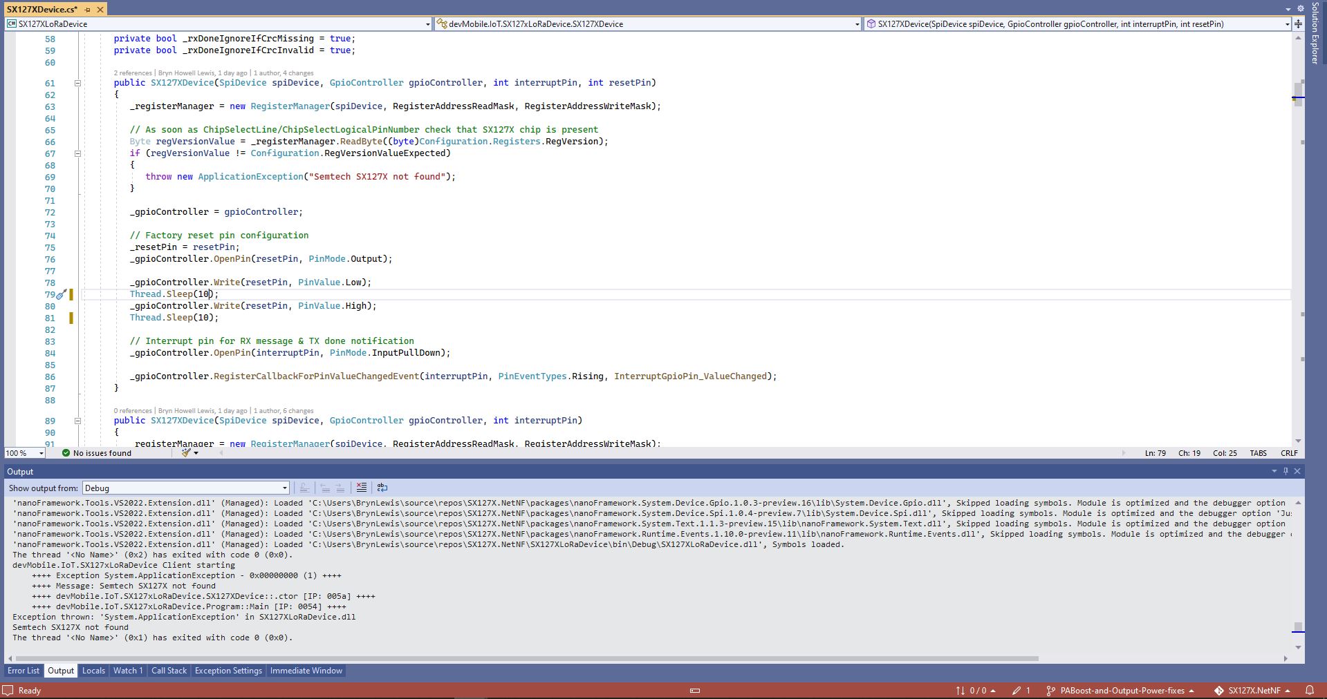
One afternoon the issue occurred several times in a row, the application wouldn’t startup because the SX127X device detection failed and message transmission was also not being confirmed.(TX Done).
Visual Studio output windows with SX127X detection failure
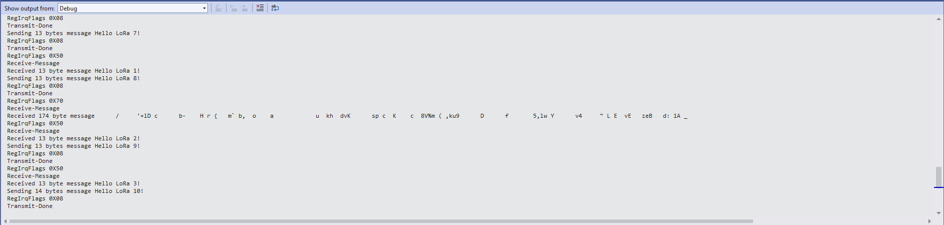
Visual Studio output windows with no Transmit confirmations
public SX127XDevice(SpiDevice spiDevice, GpioController gpioController, int interruptPin, int resetPin)
{
	_gpioController = gpioController;

	// Factory reset pin configuration
	_resetPin = resetPin;
	_gpioController.OpenPin(resetPin, PinMode.Output);

	_gpioController.Write(resetPin, PinValue.Low);
	Thread.Sleep(20);
	_gpioController.Write(resetPin, PinValue.High);
	Thread.Sleep(100);

	_registerManager = new RegisterManager(spiDevice, RegisterAddressReadMask, RegisterAddressWriteMask);

	// Once the pins setup check that SX127X chip is present
	Byte regVersionValue = _registerManager.ReadByte((byte)Configuration.Registers.RegVersion);
	if (regVersionValue != Configuration.RegVersionValueExpected)
	{
		throw new ApplicationException("Semtech SX127X not found");
	}

	// Interrupt pin for RX message & TX done notification
	_gpioController.OpenPin(interruptPin, PinMode.InputPullDown);

	_gpioController.RegisterCallbackForPinValueChangedEvent(interruptPin, PinEventTypes.Rising, InterruptGpioPin_ValueChanged);
}
I could single step through the code and inspect variables with the debugger and it looks like a timing issue with order of the strobing of the reset pin and the initialisation of the RegisterManager. I’ll spend and hour starting and stopping the application, then smoke test the code for 24 hours with a couple of other devices generating traffic just to check.
namespace devMobile.IoT.SX127xLoRaDevice
{
	using System;
	using System.Text;
	using System.Threading;

	class Program
	{
		private const double Frequency = 915000000.0;
#if ESP32_WROOM_32_LORA_1_CHANNEL
      private const int SpiBusId = 1;
#endif
#if NETDUINO3_WIFI
		private const int SpiBusId = 2;
#endif
#if ST_STM32F769I_DISCOVERY
		private const int SpiBusId = 2;
#endif
		private static SX127XDevice sx127XDevice;

		static void Main(string[] args)
		{
			int SendCount = 0;
#if ESP32_WROOM_32_LORA_1_CHANNEL // No reset line for this device as it isn't connected on SX127X
			int chipSelectLine = Gpio.IO16;
			int interruptPinNumber = Gpio.IO26;
#endif
#if NETDUINO3_WIFI
			// Arduino D10->PB10
			int chipSelectLine = PinNumber('B', 10);
			// Arduino D9->PE5
			int resetPinNumber = PinNumber('E', 5);
			// Arduino D2 -PA3
			int interruptPinNumber = PinNumber('A', 3);
#endif
#if ST_STM32F769I_DISCOVERY
			// Arduino D10->PA11
			int chipSelectLine = PinNumber('A', 11);
			// Arduino D9->PH6
			int resetPinNumber = PinNumber('H', 6);
			// Arduino D2->PA4
			int interruptPinNumber = PinNumber('J', 1);
#endif
			Console.WriteLine("devMobile.IoT.SX127xLoRaDevice Client starting");

			try
			{
#if ESP32_WROOM_32_LORA_1_CHANNEL
				Configuration.SetPinFunction(Gpio.IO12, DeviceFunction.SPI1_MISO);
				Configuration.SetPinFunction(Gpio.IO13, DeviceFunction.SPI1_MOSI);
				Configuration.SetPinFunction(Gpio.IO14, DeviceFunction.SPI1_CLOCK);

				sx127XDevice = new SX127XDevice(SpiBusId, chipSelectLine, interruptPinNumber);
#endif
#if NETDUINO3_WIFI || ST_STM32F769I_DISCOVERY
				sx127XDevice = new SX127XDevice(SpiBusId, chipSelectLine, interruptPinNumber, resetPinNumber);
#endif

				sx127XDevice.Initialise(SX127XDevice.RegOpModeMode.ReceiveContinuous,
							Frequency,
							lnaGain: SX127XDevice.RegLnaLnaGain.G3,
							lnaBoost:true,
							powerAmplifier: SX127XDevice.PowerAmplifier.PABoost,
							rxPayloadCrcOn: true,
							rxDoneignoreIfCrcMissing: false
							);

#if DEBUG
				sx127XDevice.RegisterDump();
#endif

				sx127XDevice.OnReceive += SX127XDevice_OnReceive;
				sx127XDevice.Receive();
				sx127XDevice.OnTransmit += SX127XDevice_OnTransmit;

				Thread.Sleep(500);

				while (true)
				{
					string messageText = $"Hello LoRa from .NET nanoFramework {SendCount += 1}!";

					byte[] messageBytes = UTF8Encoding.UTF8.GetBytes(messageText);
					//Console.WriteLine($"{DateTime.UtcNow:HH:mm:ss}-TX {messageBytes.Length} byte message {messageText}");
					//sx127XDevice.Send(messageBytes);

					Thread.Sleep(50000);
				}
			}
			catch (Exception ex)
			{
				Console.WriteLine(ex.Message);
			}
		}

		private static void SX127XDevice_OnReceive(object sender, SX127XDevice.OnDataReceivedEventArgs e)
		{
			try
			{
				// Remove unprintable characters from messages
				for (int index = 0; index < e.Data.Length; index++)
				{
					if ((e.Data[index] < 0x20) || (e.Data[index] > 0x7E))
					{
						e.Data[index] = 0x7C;
					}
				}

				string messageText = UTF8Encoding.UTF8.GetString(e.Data, 0, e.Data.Length);

				Console.WriteLine($"{DateTime.UtcNow:HH:mm:ss}-RX PacketSnr {e.PacketSnr:0.0} Packet RSSI {e.PacketRssi}dBm RSSI {e.Rssi}dBm = {e.Data.Length} byte message {messageText}");
			}
			catch (Exception ex)
			{
				Console.WriteLine(ex.Message);
			}
		}

		private static void SX127XDevice_OnTransmit(object sender, SX127XDevice.OnDataTransmitedEventArgs e)
		{
			sx127XDevice.SetMode(SX127XDevice.RegOpModeMode.ReceiveContinuous);

			Console.WriteLine($"{DateTime.UtcNow:HH:mm:ss}-TX Done");
		}

#if NETDUINO3_WIFI || ST_STM32F769I_DISCOVERY
		static int PinNumber(char port, byte pin)
		{
			if (port < 'A' || port > 'J')
				throw new ArgumentException();

			return ((port - 'A') * 16) + pin;
		}
#endif
	}
}
The sample application shows how to configure the library for different devices (SPI port, interrupt pin and optional reset pin) then send/receive payloads. The library is intended to be initialised then run for long periods of time (I’m looking at a month long soak test next) rather than changing configuration while running. The initialise method has many parameters which have “reasonable” default values. (Posts coming about optimising power consumption and range).
The TransmitInterrupt application loads the message to be sent into the First In First Out(FIFO) buffer, RegDioMapping1 is set to interrupt onTxDone(PacketSent-00), then RegRegOpMode-Mode is set to Transmit. When the message has been sent InterruptGpioPin_ValueChanged is called, and the TxDone(0b00001000) flag is set in the RegIrqFlags register.
The ReceiveInterrupt application sets the RegDioMapping1 to interrupt on RxDone(PacketReady-00), then the RegRegOpMode-Mode is set to Receive(TX-101). When a message is received InterruptGpioPin_ValueChanged is called, with the RxDone(0b00001000) flag set in the RegIrqFlags register, and then the message is read from First In First Out(FIFO) buffer.
namespace devMobile.IoT.SX127x.ReceiveTransmitInterrupt
{
...
   public sealed class SX127XDevice
   {
...
      public SX127XDevice(int busId, int chipSelectLine, int interruptPin, int resetPin)
      {
         var settings = new SpiConnectionSettings(busId, chipSelectLine)
         {
            ClockFrequency = 1000000,
            Mode = SpiMode.Mode0,// From SemTech docs pg 80 CPOL=0, CPHA=0
            SharingMode = SpiSharingMode.Shared
         };

         SX127XTransceiver = new SpiDevice(settings);

         GpioController gpioController = new GpioController();


         // Factory reset pin configuration
         gpioController.OpenPin(resetPin, PinMode.Output);

         gpioController.Write(resetPin, PinValue.Low);
         Thread.Sleep(20);
         gpioController.Write(resetPin, PinValue.High);
         Thread.Sleep(20);

         // Interrupt pin for RX message & TX done notification
         gpioController.OpenPin(interruptPin, PinMode.InputPullDown);

         gpioController.RegisterCallbackForPinValueChangedEvent(interruptPin, PinEventTypes.Rising, InterruptGpioPin_ValueChanged);
      }
...
   }

      private void InterruptGpioPin_ValueChanged(object sender, PinValueChangedEventArgs e)
      {
         byte irqFlags = this.ReadByte(0x12); // RegIrqFlags
         Debug.WriteLine($"RegIrqFlags 0X{irqFlags:x2}");

         if ((irqFlags & 0b01000000) == 0b01000000)  // RxDone
         {
            Debug.WriteLine("Receive-Message");
            byte currentFifoAddress = this.ReadByte(0x10); // RegFifiRxCurrent
            this.WriteByte(0x0d, currentFifoAddress); // RegFifoAddrPtr

            byte numberOfBytes = this.ReadByte(0x13); // RegRxNbBytes

            // Allocate buffer for message
            byte[] messageBytes = this.ReadBytes(0X0, numberOfBytes);

            // Remove unprintable characters from messages
            for (int index = 0; index < messageBytes.Length; index++)
            {
               if ((messageBytes[index] < 0x20) || (messageBytes[index] > 0x7E))
               {
                  messageBytes[index] = 0x20;
               }
            }

            string messageText = UTF8Encoding.UTF8.GetString(messageBytes, 0, messageBytes.Length);
            Debug.WriteLine($"Received {messageBytes.Length} byte message {messageText}");
         }

         if ((irqFlags & 0b00001000) == 0b00001000)  // TxDone
         {
            this.WriteByte(0x01, 0b10000101); // RegOpMode set LoRa & RxContinuous
            Debug.WriteLine("Transmit-Done");
         }

         this.WriteByte(0x40, 0b00000000); // RegDioMapping1 0b00000000 DI0 RxReady & TxReady
         this.WriteByte(0x12, 0xff);// RegIrqFlags
      }

   public class Program
   {
...
   #if NETDUINO3_WIFI
      private const int SpiBusId = 2;
#endif
...

      public static void Main()
      {
         int SendCount = 0;
...
#if NETDUINO3_WIFI
         // Arduino D10->PB10
         int chipSelectLine = PinNumber('B', 10);
         // Arduino D9->PE5
         int resetPinNumber = PinNumber('E', 5);
         // Arduino D2 -PA3
         int interruptPinNumber = PinNumber('A', 3);
#endif
...

       Debug.WriteLine("devMobile.IoT.SX127x.ReceiveTransmitInterrupt starting");

         try
         {
...
#if NETDUINO3_WIFI || ST_STM32F769I_DISCOVERY
            SX127XDevice sx127XDevice = new SX127XDevice(SpiBusId, chipSelectLine, interruptPinNumber, resetPinNumber);
#endif
            Thread.Sleep(500);

            // Put device into LoRa + Sleep mode
            sx127XDevice.WriteByte(0x01, 0b10000000); // RegOpMode

            // Set the frequency to 915MHz
            byte[] frequencyWriteBytes = { 0xE4, 0xC0, 0x00 }; // RegFrMsb, RegFrMid, RegFrLsb
            sx127XDevice.WriteBytes(0x06, frequencyWriteBytes);

            // More power PA Boost
            sx127XDevice.WriteByte(0x09, 0b10000000); // RegPaConfig

            sx127XDevice.WriteByte(0x01, 0b10000101); // RegOpMode set LoRa & RxContinuous

            while (true)
            {
               // Set the Register Fifo address pointer
               sx127XDevice.WriteByte(0x0E, 0x00); // RegFifoTxBaseAddress

               // Set the Register Fifo address pointer
               sx127XDevice.WriteByte(0x0D, 0x0); // RegFifoAddrPtr

               string messageText = $"Hello LoRa {SendCount += 1}!";

               // load the message into the fifo
               byte[] messageBytes = UTF8Encoding.UTF8.GetBytes(messageText);
               sx127XDevice.WriteBytes(0x0, messageBytes); // RegFifo

               // Set the length of the message in the fifo
               sx127XDevice.WriteByte(0x22, (byte)messageBytes.Length); // RegPayloadLength
               sx127XDevice.WriteByte(0x40, 0b01000000); // RegDioMapping1 0b00000000 DI0 RxReady & TxReady
               sx127XDevice.WriteByte(0x01, 0b10000011); // RegOpMode

               Debug.WriteLine($"Sending {messageBytes.Length} bytes message {messageText}");

               Thread.Sleep(10000);
            }
         }
         catch (Exception ex)
         {
            Debug.WriteLine(ex.Message);
         }
      }
...
   }
}
ReceiveTransmitInterrupt application output
The ReceiveTransmitInterrupt application combines the functionality TransmitInterrupt and ReceiveInterrupt programs. The key differences are the RegDioMapping1 setup and in InterruptGpioPin_ValueChanged where the TxDone & RxDone flags in the RegIrqFlags register specify how the interrupt is handled.
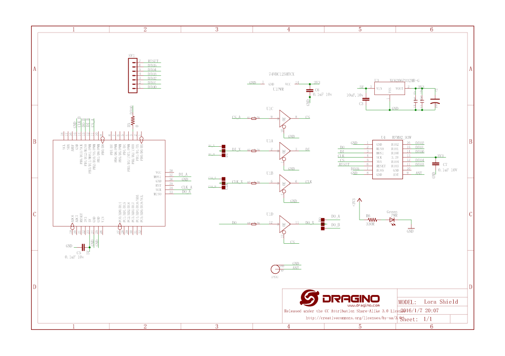
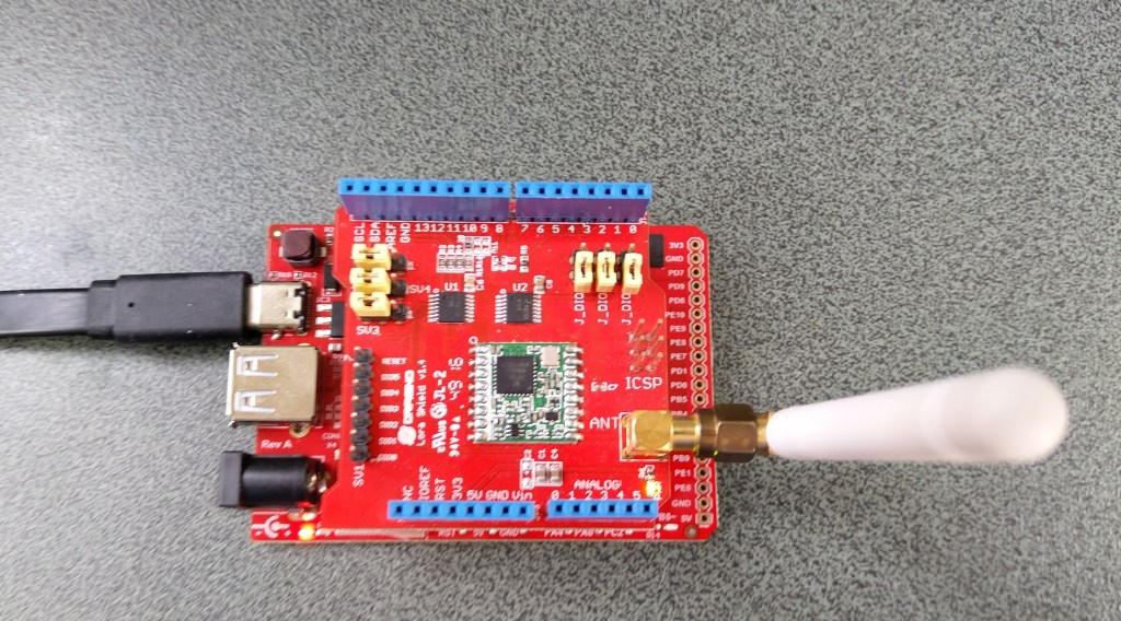
For testing nanoFramework device transmit and receive functionality I used an Arduino/Seeeduino with a Dragino LoRa Shield (running one of the Arduino-LoRa samples) as a client device. This was so I could “bootstrap” connectivity and test interoperability with other libraries/platforms.
Arduino/Netduino devices for .NET nanoFramework interoperability test-rig
I started with transmit as I was confident my Seeeduino + Dragino LoRa Shield could receive messages. The TransmitBasic application puts the device into LoRa + Sleep mode as after reset/powering up the device is in FSK/OOK, Low Frequency + Standby mode).
SX127X RegOpMode options
After loading the message to be sent into the First In First Out(FIFO) buffer, the RegOpMode-Mode is set to Transmit(TX-011), and then the RegIrqFlags register is polled until the TxDone flag is set.
SX127X ReqIrqFlags options
public static void Main()
{
  int SendCount = 0;
...
  Debug.WriteLine("devMobile.IoT.SX127x.TransmitBasic starting");

   try
   {
...
#if NETDUINO3_WIFI || ST_STM32F769I_DISCOVERY
      SX127XDevice sx127XDevice = new SX127XDevice(SpiBusId, chipSelectLine, resetPinNumber);
#endif
     Thread.Sleep(500);

     // Put device into LoRa + Standby mode
     sx127XDevice.WriteByte(0x01, 0b10000000); // RegOpMode

      // Set the frequency to 915MHz
      byte[] frequencyBytes = { 0xE4, 0xC0, 0x00 }; // RegFrMsb, RegFrMid, RegFrLsb
      sx127XDevice.WriteBytes(0x06, frequencyBytes);

      // More power PA Boost
      sx127XDevice.WriteByte(0x09, 0b10000000); // RegPaConfig

      sx127XDevice.RegisterDump();

      while (true)
      {
         sx127XDevice.WriteByte(0x0E, 0x0); // RegFifoTxBaseAddress

         // Set the Register Fifo address pointer
         sx127XDevice.WriteByte(0x0D, 0x0); // RegFifoAddrPtr

         string messageText = $"Hello LoRa from .NET nanoFramework {SendCount += 1}!";

         // load the message into the fifo
         byte[] messageBytes = UTF8Encoding.UTF8.GetBytes(messageText);
         sx127XDevice.WriteBytes(0x0, messageBytes); // RegFifo

         // Set the length of the message in the fifo
         sx127XDevice.WriteByte(0x22, (byte)messageBytes.Length); // RegPayloadLength

         Debug.WriteLine($"Sending {messageBytes.Length} bytes message {messageText}");
         // Set the mode to LoRa + Transmit
         sx127XDevice.WriteByte(0x01, 0b10000011); // RegOpMode

         // Wait until send done, no timeouts in PoC
         Debug.WriteLine("Send-wait");
         byte irqFlags = sx127XDevice.ReadByte(0x12); // RegIrqFlags
         while ((irqFlags & 0b00001000) == 0)  // wait until TxDone cleared
         {
            Thread.Sleep(10);
            irqFlags = sx127XDevice.ReadByte(0x12); // RegIrqFlags
            Debug.Write(".");
         }
         Debug.WriteLine("");
         sx127XDevice.WriteByte(0x12, 0b00001000); // clear TxDone bit
         Debug.WriteLine("Send-Done");

         Thread.Sleep(30000);
         }
      }
      catch (Exception ex)
      {
         Debug.WriteLine(ex.Message);
      }
   }
}
Transmit Basic application output
Once the TransmitBasic application was sending messages reliably I started working on the ReceiveBasic application. As the ReceiveBasic application starts up the SX127X RegOpMode has to be set to sleep/standby so the device can be configured. TOnce that is completed RegOpMode-Mode is set to RxContinuous(101), and the RegIrqFlags register is polled until the RxDone flag is set.
public static void Main()
{
...
   Debug.WriteLine("devMobile.IoT.SX127x.ReceiveBasic starting");

   try
   {
...
#if NETDUINO3_WIFI || ST_STM32F769I_DISCOVERY
      SX127XDevice sx127XDevice = new SX127XDevice(SpiBusId, chipSelectLine, resetPinNumber);
#endif
      Thread.Sleep(500);

      // Put device into LoRa + Sleep mode
      sx127XDevice.WriteByte(0x01, 0b10000000); // RegOpMode

      // Set the frequency to 915MHz
      byte[] frequencyBytes = { 0xE4, 0xC0, 0x00 }; // RegFrMsb, RegFrMid, RegFrLsb
      sx127XDevice.WriteBytes(0x06, frequencyBytes);

      sx127XDevice.WriteByte(0x0F, 0x0); // RegFifoRxBaseAddress

      sx127XDevice.WriteByte(0x01, 0b10000101); // RegOpMode set LoRa & RxContinuous

       while (true)
       {
          // Wait until a packet is received, no timeouts in PoC
         Debug.WriteLine("Receive-Wait");
         byte irqFlags = sx127XDevice.ReadByte(0x12); // RegIrqFlags
         while ((irqFlags & 0b01000000) == 0)  // wait until RxDone cleared
         {
            Thread.Sleep(100);
            irqFlags = sx127XDevice.ReadByte(0x12); // RegIrqFlags
            Debug.Write(".");
         }
         Debug.WriteLine("");
         Debug.WriteLine($"RegIrqFlags 0X{irqFlags:X2}");
         Debug.WriteLine("Receive-Message");
         byte currentFifoAddress = sx127XDevice.ReadByte(0x10); // RegFifiRxCurrent
         sx127XDevice.WriteByte(0x0d, currentFifoAddress); // RegFifoAddrPtr

         byte numberOfBytes = sx127XDevice.ReadByte(0x13); // RegRxNbBytes

         // Read the message from the FIFO
         byte[] messageBytes = sx127XDevice.ReadBytes(0x00, numberOfBytes);

         sx127XDevice.WriteByte(0x0d, 0);
         sx127XDevice.WriteByte(0x12, 0b11111111); // RegIrqFlags clear all the bits

         // Remove unprintable characters from messages
         for (int index = 0; index < messageBytes.Length; index++)
         {
            if ((messageBytes[index] < 0x20) || (messageBytes[index] > 0x7E))
            {
               messageBytes[index] = 0x20;
            }
         }

         string messageText = UTF8Encoding.UTF8.GetString(messageBytes, 0, messageBytes.Length);
         Debug.WriteLine($"Received {messageBytes.Length} byte message {messageText}");

         Debug.WriteLine("Receive-Done");
      }
    }
   catch (Exception ex)
   {
      Debug.WriteLine(ex.Message);
   }
}
Receive Basic application output
Every so often the ReceiveBasic application would display a message sent on the same frequency by a device somewhere nearby.
ReceiveBasic application messages from unknown source
I need to do some more investigation into whether writing 0b00001000 (Transmit) vs. 0b11111111(Receive) to RegIrqFlags is important.
Now that I could reliably dump all the Dragino shield registers I wanted to be able to configure the Semtech 127X device and reset it back to factory settings. A factory reset is done by strobing the SX127X reset pin.
SX127X Reset timing diagram
SX127X Reset process
To support this I added a constructor with an additional parameter for the reset General Purpose Input Output(GPIO) pin number to the SX127XDevice class. The original constructor was retained as the SX127X reset pin is not connected on the SparkFun LoRa Gateway-1-Channel (ESP32) and a limited number of other devices.
namespace devMobile.IoT.SX127x.RegisterReadAndWrite
{
   using System;
   using System.Diagnostics;
   using System.Threading;

   using System.Device.Gpio;
   using System.Device.Spi;

#if ESP32_WROOM_32_LORA_1_CHANNEL
   using nanoFramework.Hardware.Esp32;
#endif

   public sealed class SX127XDevice
   {
      private const byte RegisterAddressMinimum = 0X0;
      private const byte RegisterAddressMaximum = 0x42;
      private const byte RegisterAddressReadMask = 0X7f;
      private const byte RegisterAddressWriteMask = 0x80;

      private readonly SpiDevice SX127XTransceiver;

      public SX127XDevice(int busId, int chipSelectLine, int resetPin)
      {
         var settings = new SpiConnectionSettings(busId, chipSelectLine)
         {
            ClockFrequency = 1000000,
            Mode = SpiMode.Mode0,// From SemTech docs pg 80 CPOL=0, CPHA=0
            SharingMode = SpiSharingMode.Shared
         };

         SX127XTransceiver = new SpiDevice(settings);

         // Factory reset pin configuration
         GpioController gpioController = new GpioController();
         gpioController.OpenPin(resetPin, PinMode.Output);

         gpioController.Write(resetPin, PinValue.Low);
         Thread.Sleep(20);
         gpioController.Write(resetPin, PinValue.High);
         Thread.Sleep(20);
      }

      public SX127XDevice(int busId, int chipSelectLine)
      {
         var settings = new SpiConnectionSettings(busId, chipSelectLine)
         {
            ClockFrequency = 1000000,
            Mode = SpiMode.Mode0,// From SemTech docs pg 80 CPOL=0, CPHA=0
            SharingMode = SpiSharingMode.Shared,
         };

         SX127XTransceiver = new SpiDevice(settings);
      }

      public Byte ReadByte(byte registerAddress)
      {
         byte[] writeBuffer = new byte[] { registerAddress &= RegisterAddressReadMask, 0x0 };
         byte[] readBuffer = new byte[writeBuffer.Length];

         SX127XTransceiver.TransferFullDuplex(writeBuffer, readBuffer);

         return readBuffer[1];
      }

      public ushort ReadWord(byte address)
      {
         byte[] writeBuffer = new byte[] { address &= RegisterAddressReadMask, 0x0, 0x0 };
         byte[] readBuffer = new byte[writeBuffer.Length];

         SX127XTransceiver.TransferFullDuplex(writeBuffer, readBuffer);

         return (ushort)(readBuffer[2] + (readBuffer[1] << 8));
      }

      public ushort ReadWordMsbLsb(byte address)
      {
         byte[] writeBuffer = new byte[] { address &= RegisterAddressReadMask, 0x0, 0x0 };
         byte[] readBuffer = new byte[writeBuffer.Length];

         SX127XTransceiver.TransferFullDuplex(writeBuffer, readBuffer);

         return (ushort)((readBuffer[1] << 8) + readBuffer[2]);
      }

      public byte[] ReadBytes(byte address, byte length)
      {
         byte[] writeBuffer = new byte[length + 1];
         byte[] readBuffer = new byte[writeBuffer.Length];
         byte[] replyBuffer = new byte[length];

         writeBuffer[0] = address &= RegisterAddressReadMask;

         SX127XTransceiver.TransferFullDuplex(writeBuffer, readBuffer);

         Array.Copy(readBuffer, 1, replyBuffer, 0, length);

         return replyBuffer;
      }

      public void WriteByte(byte address, byte value)
      {
         byte[] writeBuffer = new byte[] { address |= RegisterAddressWriteMask, value };
         byte[] readBuffer = new byte[writeBuffer.Length];

         SX127XTransceiver.TransferFullDuplex(writeBuffer, readBuffer);
      }

      public void WriteWord(byte address, ushort value)
      {
         byte[] valueBytes = BitConverter.GetBytes(value);
         byte[] writeBuffer = new byte[] { address |= RegisterAddressWriteMask, valueBytes[0], valueBytes[1] };
         byte[] readBuffer = new byte[writeBuffer.Length];

         SX127XTransceiver.TransferFullDuplex(writeBuffer, readBuffer);
      }

      public void WriteWordMsbLsb(byte address, ushort value)
      {
         byte[] valueBytes = BitConverter.GetBytes(value);
         byte[] writeBuffer = new byte[] { address |= RegisterAddressWriteMask, valueBytes[1], valueBytes[0] };
         byte[] readBuffer = new byte[writeBuffer.Length];

         SX127XTransceiver.TransferFullDuplex(writeBuffer, readBuffer);
      }

      public void WriteBytes(byte address, byte[] bytes)
      {
         byte[] writeBuffer = new byte[1 + bytes.Length];
         byte[] readBuffer = new byte[writeBuffer.Length];

         Array.Copy(bytes, 0, writeBuffer, 1, bytes.Length);
         writeBuffer[0] = address |= RegisterAddressWriteMask;

         SX127XTransceiver.TransferFullDuplex(writeBuffer, readBuffer);
      }

      public void RegisterDump()
      {
         Debug.WriteLine("Register dump");
         for (byte registerIndex = RegisterAddressMinimum; registerIndex <= RegisterAddressMaximum; registerIndex++)
         {
            byte registerValue = this.ReadByte(registerIndex);

            Debug.WriteLine($"Register 0x{registerIndex:x2} - Value 0X{registerValue:x2}");
         }

         Debug.WriteLine("");
      }
   }

   public class Program
   {
#if ESP32_WROOM_32_LORA_1_CHANNEL
      private const int SpiBusId = 1;
#endif
#if NETDUINO3_WIFI
      private const int SpiBusId = 2;
#endif
#if ST_STM32F769I_DISCOVERY
      private const int SpiBusId = 2;
#endif


      public static void Main()
      {
         byte[] frequencyBytes;
#if ESP32_WROOM_32_LORA_1_CHANNEL // No reset line for this device as it isn't connected on SX127X
         int chipSelectLine = Gpio.IO16;
#endif
#if NETDUINO3_WIFI
         // Arduino D10->PB10
         int chipSelectLine = PinNumber('B', 10);
         // Arduino D9->PE5
         int resetPinNumber = PinNumber('E', 5);
#endif
#if ST_STM32F769I_DISCOVERY
         // Arduino D10->PA11
         int chipSelectLine = PinNumber('A', 11);
         // Arduino D9->PH6
         int resetPinNumber = PinNumber('H', 6);
#endif

         Debug.WriteLine("devMobile.IoT.SX127x.RegisterReadAndWrite starting");

         try
         {
#if ESP32_WROOM_32_LORA_1_CHANNEL
            Configuration.SetPinFunction(Gpio.IO12, DeviceFunction.SPI1_MISO);
            Configuration.SetPinFunction(Gpio.IO13, DeviceFunction.SPI1_MOSI);
            Configuration.SetPinFunction(Gpio.IO14, DeviceFunction.SPI1_CLOCK);

            SX127XDevice sx127XDevice = new SX127XDevice(SpiBusId, chipSelectLine);
#endif
#if NETDUINO3_WIFI || ST_STM32F769I_DISCOVERY
            SX127XDevice sx127XDevice = new SX127XDevice(SpiBusId, chipSelectLine, resetPinNumber);
#endif
            Thread.Sleep(500);

            sx127XDevice.RegisterDump();

            while (true)
            {
               Debug.WriteLine("Read RegOpMode (read byte)");
               Byte regOpMode1 = sx127XDevice.ReadByte(0x1);
               Debug.WriteLine($"RegOpMode 0x{regOpMode1:x2}");

               Debug.WriteLine("Set LoRa mode and sleep mode (write byte)");
               sx127XDevice.WriteByte(0x01, 0b10000000);

               Debug.WriteLine("Read RegOpMode (read byte)");
               Byte regOpMode2 = sx127XDevice.ReadByte(0x1);
               Debug.WriteLine($"RegOpMode 0x{regOpMode2:x2}");

               Debug.WriteLine("Read the preamble (read word)");
               ushort preamble = sx127XDevice.ReadWord(0x20);
               Debug.WriteLine($"Preamble 0x{preamble:x2}");

	            Console.WriteLine("Read the preamble (read word)"); // Should be 0x08
			      preamble = sx127XDevice.ReadWordMsbLsb(0x20);
               Debug.WriteLine($"Preamble 0x{preamble:x2}");

               Debug.WriteLine("Read the centre frequency (read byte array)");
               frequencyBytes = sx127XDevice.ReadBytes(0x06, 3);
               Debug.WriteLine($"Frequency Msb 0x{frequencyBytes[0]:x2} Mid 0x{frequencyBytes[1]:x2} Lsb 0x{frequencyBytes[2]:x2}");

               Debug.WriteLine("Set the centre frequency to 915MHz (write byte array)");
               byte[] frequencyWriteBytes = { 0xE4, 0xC0, 0x00 };
               sx127XDevice.WriteBytes(0x06, frequencyWriteBytes);

               Debug.WriteLine("Read the centre frequency (read byte array)");
               frequencyBytes = sx127XDevice.ReadBytes(0x06, 3);
               Debug.WriteLine($"Frequency Msb 0x{frequencyBytes[0]:x2} Mid 0x{frequencyBytes[1]:x2} Lsb 0x{frequencyBytes[2]:x2}");

               sx127XDevice.RegisterDump();

               Thread.Sleep(30000);
            }
         }
         catch (Exception ex)
         {
            Debug.WriteLine(ex.Message);
         }
      }

#if NETDUINO3_WIFI || ST_STM32F769I_DISCOVERY
      static int PinNumber(char port, byte pin)
      {
         if (port < 'A' || port > 'J')
            throw new ArgumentException();

         return ((port - 'A') * 16) + pin;
      }
#endif
   }
}
The PinNumber helper is more user friendly that the raw numbers and is “inspired” by sample .NET nanoFramework General Purpose Input Output(GPIO) sample code.
Each method was tested by read/writing suitable register(s) in the device configuration (Needed to set it into LoRa mode first).
The next step is to extract the Serial Peripheral Interface(SPI) register access functionality into a module and configure the bare minimum of settings required to get the SX127X to receive and transmit messages.
All this madness started because I wasn’t confident the frequency calculation of the Emmellsoft Dragino.Lora code was correct. Over the last couple of years I have also found bugs in my Transmit Power, InvertIQ RX/TX with many others yet to be discovered.
Need to be careful not to push the Dragino shield in too far as a couple of the pins (one is not connected and the other is IOREF) will contact the Micro SD card slot. (I have put a strip of Duct tape on the top of the Micro SD card socket)
Fezduino pin clearance
The first step was to get basic connectivity sorted. I opened the RFM9XLoRa-TinyCLR repository and modified the Serial Peripheral Interface(SPI) and chip select(CS) settings of the ShieldSPI project, then updated the NuGet packages (public feed rather than my local preview files).
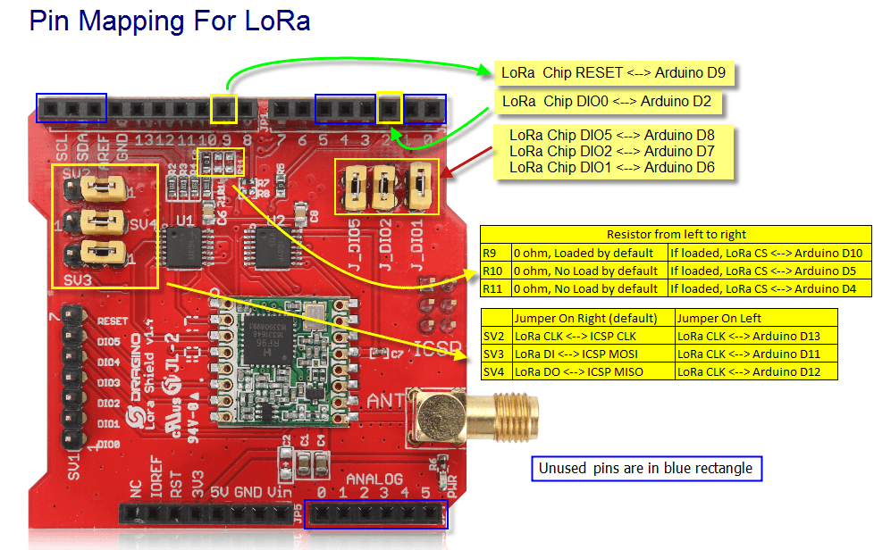
Dragino LoRa Shield for Arduino pins
I have left the TinyCLR V1 configuration in for backward compatibility
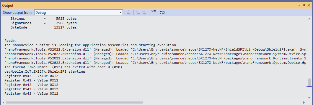
When I ran the application in Visual Studio I could reliably read the RegVersion register.
The thread '<No Name>' (0x2) has exited with code 0 (0x0).
Value = 0x00-12
Value = 0x00-12
Value = 0x00-12
Value = 0x00-12
Value = 0x00-12
Value = 0x00-12
The program '[5] TinyCLR application: Managed' has exited with code 0 (0x0).
The next step was to modify the RegisterScan project to check I could read all the SX127X configuration registers.
  class Program
   {
      static void Main()
      {
#if TINYCLR_V2_SC20100DEV
         Rfm9XDevice rfm9XDevice = new Rfm9XDevice(SC20100.SpiBus.Spi3, SC20100.GpioPin.PA13);
#endif
#if TINYCLR_V2_FEZDUINO
         Rfm9XDevice rfm9XDevice = new Rfm9XDevice(SC20100.SpiBus.Spi6, SC20100.GpioPin.PB1);
#endif

         while (true)
         {
            for (byte registerIndex = 0; registerIndex <= 0x42; registerIndex++)
            {
               byte registerValue = rfm9XDevice.RegisterReadByte(registerIndex);

               Debug.WriteLine($"Register 0x{registerIndex:x2} - Value 0X{registerValue:x2}");
            }
            Debug.WriteLine("");

            Thread.Sleep(10000);
         }
      }
   }
When I ran the application in Visual Studio I could reliably read the registers 0x00 through 0x42.
The thread '<No Name>' (0x2) has exited with code 0 (0x0).
Register 0x00 - Value 0X00
Register 0x01 - Value 0X09
Register 0x02 - Value 0X1a
Register 0x03 - Value 0X0b
Register 0x04 - Value 0X00
Register 0x05 - Value 0X52
Register 0x06 - Value 0X6c
Register 0x07 - Value 0X80
Register 0x08 - Value 0X00
Register 0x09 - Value 0X4f
Register 0x0a - Value 0X09
Register 0x0b - Value 0X2b
Register 0x0c - Value 0X20
Register 0x0d - Value 0X08
Register 0x0e - Value 0X02
Register 0x0f - Value 0X0a
Register 0x10 - Value 0Xff
Register 0x11 - Value 0X71
Register 0x12 - Value 0X15
Register 0x13 - Value 0X0b
Register 0x14 - Value 0X28
Register 0x15 - Value 0X0c
Register 0x16 - Value 0X12
Register 0x17 - Value 0X47
Register 0x18 - Value 0X32
Register 0x19 - Value 0X3e
Register 0x1a - Value 0X00
Register 0x1b - Value 0X00
Register 0x1c - Value 0X00
Register 0x1d - Value 0X00
Register 0x1e - Value 0X00
Register 0x1f - Value 0X40
Register 0x20 - Value 0X00
Register 0x21 - Value 0X00
Register 0x22 - Value 0X00
Register 0x23 - Value 0X00
Register 0x24 - Value 0X05
Register 0x25 - Value 0X00
Register 0x26 - Value 0X03
Register 0x27 - Value 0X93
Register 0x28 - Value 0X55
Register 0x29 - Value 0X55
Register 0x2a - Value 0X55
Register 0x2b - Value 0X55
Register 0x2c - Value 0X55
Register 0x2d - Value 0X55
Register 0x2e - Value 0X55
Register 0x2f - Value 0X55
Register 0x30 - Value 0X90
Register 0x31 - Value 0X40
Register 0x32 - Value 0X40
Register 0x33 - Value 0X00
Register 0x34 - Value 0X00
Register 0x35 - Value 0X0f
Register 0x36 - Value 0X00
Register 0x37 - Value 0X00
Register 0x38 - Value 0X00
Register 0x39 - Value 0Xf5
Register 0x3a - Value 0X20
Register 0x3b - Value 0X82
Register 0x3c - Value 0Xfb
Register 0x3d - Value 0X02
Register 0x3e - Value 0X80
Register 0x3f - Value 0X40
Register 0x40 - Value 0X00
Register 0x41 - Value 0X00
Register 0x42 - Value 0X12
The next step was to modify the RegisterReadAndWrite project to check I could read and write the SX127X configuration registers.
     class Program
   {
      static void Main()
      {
#if TINYCLR_V2_SC20100DEV
         Rfm9XDevice rfm9XDevice = new Rfm9XDevice(SC20100.SpiBus.Spi3, SC20100.GpioPin.PA13, SC20100.GpioPin.PA14);
#endif
#if TINYCLR_V2_FEZDUINO
         Rfm9XDevice rfm9XDevice = new Rfm9XDevice(SC20100.SpiBus.Spi6, SC20100.GpioPin.PB1, SC20100.GpioPin.PA15);
#endif

         rfm9XDevice.RegisterDump();

         while (true)
         {
            Debug.WriteLine("Read RegOpMode (read byte)");
            Byte regOpMode1 = rfm9XDevice.RegisterReadByte(0x1);
            Debug.WriteLine($"RegOpMode 0x{regOpMode1:x2}");

            Debug.WriteLine("Set LoRa mode and sleep mode (write byte)");
            rfm9XDevice.RegisterWriteByte(0x01, 0b10000000);

            Debug.WriteLine("Read RegOpMode (read byte)");
            Byte regOpMode2 = rfm9XDevice.RegisterReadByte(0x1);
            Debug.WriteLine($"RegOpMode 0x{regOpMode2:x2}");

            Debug.WriteLine("Read the preamble (read word)");
            ushort preamble = rfm9XDevice.RegisterReadWord(0x20);
            Debug.WriteLine($"Preamble 0x{preamble:x2}");

            Debug.WriteLine("Set the preamble to 0x80 (write word)");
            rfm9XDevice.RegisterWriteWord(0x20, 0x80);

            Debug.WriteLine("Read the center frequency (read byte array)");
            byte[] frequencyReadBytes = rfm9XDevice.RegisterRead(0x06, 3);
            Debug.WriteLine($"Frequency Msb 0x{frequencyReadBytes[0]:x2} Mid 0x{frequencyReadBytes[1]:x2} Lsb 0x{frequencyReadBytes[2]:x2}");

            Debug.WriteLine("Set the center frequency to 915MHz (write byte array)");
            byte[] frequencyWriteBytes = { 0xE4, 0xC0, 0x00 };
            rfm9XDevice.RegisterWrite(0x06, frequencyWriteBytes);

            rfm9XDevice.RegisterDump();

            Thread.Sleep(30000);
         }
      }
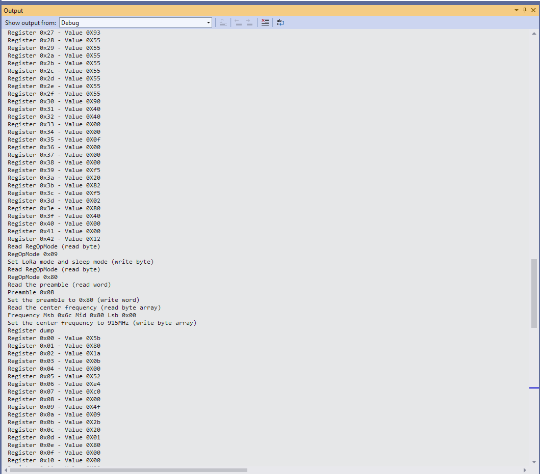
When I ran the application in Visual Studio I could read and write register values.
The thread '<No Name>' (0x2) has exited with code 0 (0x0).
Register dump
Register 0x00 - Value 0X00
Register 0x01 - Value 0X09
Register 0x02 - Value 0X1a
Register 0x03 - Value 0X0b
Register 0x04 - Value 0X00
Register 0x05 - Value 0X52
Register 0x06 - Value 0X6c
Register 0x07 - Value 0X80
Register 0x08 - Value 0X00
Register 0x09 - Value 0X4f
Register 0x0a - Value 0X09
Register 0x0b - Value 0X2b
Register 0x0c - Value 0X20
Register 0x0d - Value 0X08
Register 0x0e - Value 0X02
Register 0x0f - Value 0X0a
Register 0x10 - Value 0Xff
Register 0x11 - Value 0X71
Register 0x12 - Value 0X15
Register 0x13 - Value 0X0b
Register 0x14 - Value 0X28
Register 0x15 - Value 0X0c
Register 0x16 - Value 0X12
Register 0x17 - Value 0X47
Register 0x18 - Value 0X32
Register 0x19 - Value 0X3e
Register 0x1a - Value 0X00
Register 0x1b - Value 0X00
Register 0x1c - Value 0X00
Register 0x1d - Value 0X00
Register 0x1e - Value 0X00
Register 0x1f - Value 0X40
Register 0x20 - Value 0X00
Register 0x21 - Value 0X00
Register 0x22 - Value 0X00
Register 0x23 - Value 0X00
Register 0x24 - Value 0X05
Register 0x25 - Value 0X00
Register 0x26 - Value 0X03
Register 0x27 - Value 0X93
Register 0x28 - Value 0X55
Register 0x29 - Value 0X55
Register 0x2a - Value 0X55
Register 0x2b - Value 0X55
Register 0x2c - Value 0X55
Register 0x2d - Value 0X55
Register 0x2e - Value 0X55
Register 0x2f - Value 0X55
Register 0x30 - Value 0X90
Register 0x31 - Value 0X40
Register 0x32 - Value 0X40
Register 0x33 - Value 0X00
Register 0x34 - Value 0X00
Register 0x35 - Value 0X0f
Register 0x36 - Value 0X00
Register 0x37 - Value 0X00
Register 0x38 - Value 0X00
Register 0x39 - Value 0Xf5
Register 0x3a - Value 0X20
Register 0x3b - Value 0X82
Register 0x3c - Value 0Xfa
Register 0x3d - Value 0X02
Register 0x3e - Value 0X80
Register 0x3f - Value 0X40
Register 0x40 - Value 0X00
Register 0x41 - Value 0X00
Register 0x42 - Value 0X12
Read RegOpMode (read byte)
RegOpMode 0x09
Set LoRa mode and sleep mode (write byte)
Read RegOpMode (read byte)
RegOpMode 0x80
Read the preamble (read word)
Preamble 0x08
Set the preamble to 0x80 (write word)
Read the center frequency (read byte array)
Frequency Msb 0x6c Mid 0x80 Lsb 0x00
Set the center frequency to 915MHz (write byte array)
Register dump
Register 0x00 - Value 0Xc3
Register 0x01 - Value 0X80
Register 0x02 - Value 0X1a
Register 0x03 - Value 0X0b
Register 0x04 - Value 0X00
Register 0x05 - Value 0X52
Register 0x06 - Value 0Xe4
Register 0x07 - Value 0Xc0
Register 0x08 - Value 0X00
Register 0x09 - Value 0X4f
Register 0x0a - Value 0X09
Register 0x0b - Value 0X2b
Register 0x0c - Value 0X20
Register 0x0d - Value 0X01
Register 0x0e - Value 0X80
Register 0x0f - Value 0X00
Register 0x10 - Value 0X00
Register 0x11 - Value 0X00
Register 0x12 - Value 0X00
Register 0x13 - Value 0X00
Register 0x14 - Value 0X00
Register 0x15 - Value 0X00
Register 0x16 - Value 0X00
Register 0x17 - Value 0X00
Register 0x18 - Value 0X10
Register 0x19 - Value 0X00
Register 0x1a - Value 0X00
Register 0x1b - Value 0X00
Register 0x1c - Value 0X00
Register 0x1d - Value 0X72
Register 0x1e - Value 0X70
Register 0x1f - Value 0X64
Register 0x20 - Value 0X80
Register 0x21 - Value 0X00
Register 0x22 - Value 0X01
Register 0x23 - Value 0Xff
Register 0x24 - Value 0X00
Register 0x25 - Value 0X00
Register 0x26 - Value 0X04
Register 0x27 - Value 0X00
Register 0x28 - Value 0X00
Register 0x29 - Value 0X00
Register 0x2a - Value 0X00
Register 0x2b - Value 0X00
Register 0x2c - Value 0X00
Register 0x2d - Value 0X50
Register 0x2e - Value 0X14
Register 0x2f - Value 0X45
Register 0x30 - Value 0X55
Register 0x31 - Value 0Xc3
Register 0x32 - Value 0X05
Register 0x33 - Value 0X27
Register 0x34 - Value 0X1c
Register 0x35 - Value 0X0a
Register 0x36 - Value 0X03
Register 0x37 - Value 0X0a
Register 0x38 - Value 0X42
Register 0x39 - Value 0X12
Register 0x3a - Value 0X49
Register 0x3b - Value 0X1d
Register 0x3c - Value 0X00
Register 0x3d - Value 0Xaf
Register 0x3e - Value 0X00
Register 0x3f - Value 0X00
Register 0x40 - Value 0X00
Register 0x41 - Value 0X00
Register 0x42 - Value 0X12
At this point I was confident that I could hardware reset the shield and read/modify registers on the SX127X.