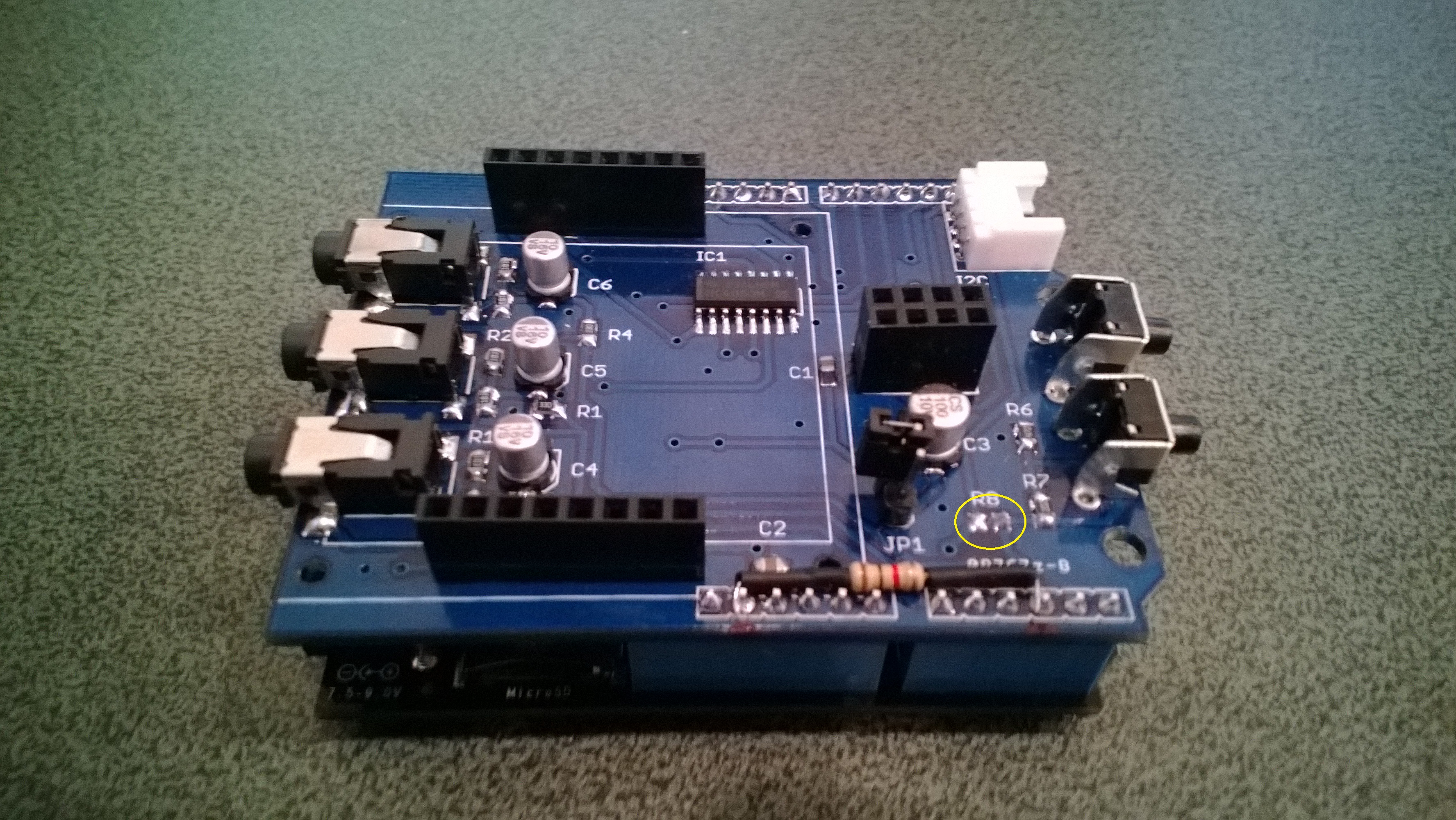
The energy monitor shield has three current sensor inputs (A0 thru A2) which have a voltage divider to provide a reference offset voltage for the analog inputs on the Netduino. The reference offset voltage with a 5V supply was 2.5V which meant on a 3.3V device the range of the sensors (1V for 30 Amps) would be compromised.
In a previous post I modified the shield by replacing a resistor but there appears to be an easier modification. While looking at the schematic and the shield I realised that cutting off the 5V pin and connecting the 3.3V pin and 5V pin together would make all the analog inputs use the 3.3V rail.
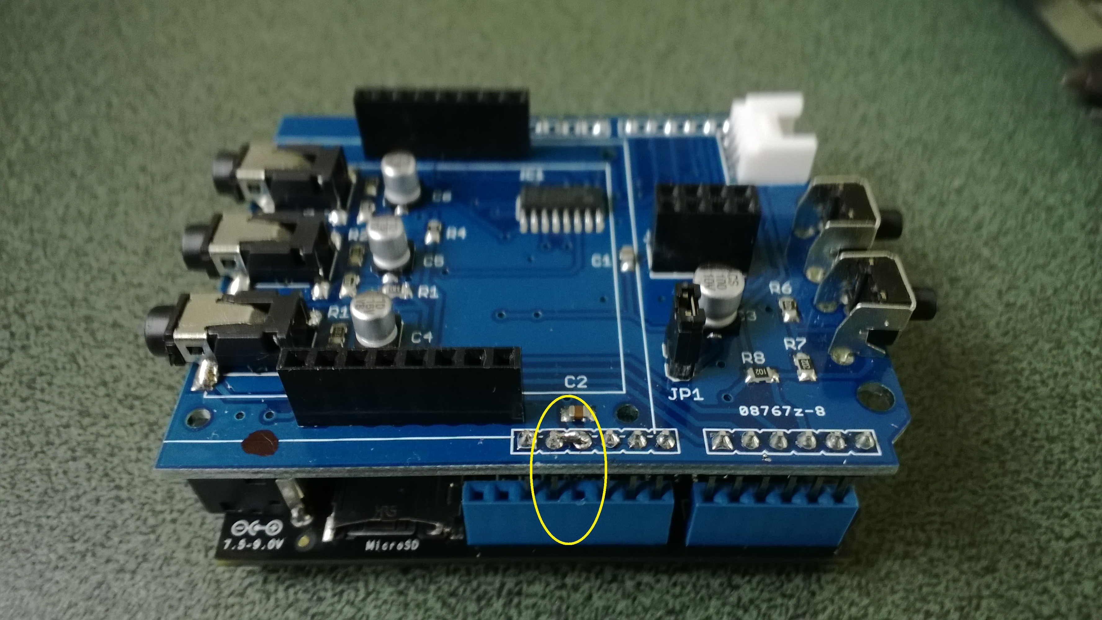
Energy Shield with modifications for 3.3V operation
It would be good if the designers of the shield would consider putting a switch or jumpers on the device to allow 3V3 or 5V operation.
public class Program
{
public static void Main()
{
AnalogInput buttons = new AnalogInput(Cpu.AnalogChannel.ANALOG_0);
while (true)
{
Debug.Print(buttons.Read().ToString(“F2”));
Thread.Sleep(250);
}
}
}