nanoFramework nRF24L01 library Part2

After sorting out Serial Peripheral Interface(SPI) connectivity the next step porting my GHI Electronics TinyCLR V2 library to the nanoFramework was rewriting the initialisation code. Overall changes were minimal as the nanoFramework similar methods to the TinyCLR V2 ones.

The Tiny CLR SPI and interrupt port configuration (note the slightly different interrupt port configuration)

if (gpio == null)
{
   Debug.WriteLine("GPIO Initialization failed.");
}
else
{
   _cePin = gpio.OpenPin(chipEnablePin);
   _cePin.SetDriveMode(GpioPinDriveMode.Output);
   _cePin.Write(GpioPinValue.Low);

   _irqPin = gpio.OpenPin((byte)interruptPin);
   _irqPin.SetDriveMode(GpioPinDriveMode.InputPullUp);
   _irqPin.Write(GpioPinValue.High);
   _irqPin.ValueChanged += _irqPin_ValueChanged;
}

try
{
   var settings = new SpiConnectionSettings()
   {
      ChipSelectType = SpiChipSelectType.Gpio,
      ChipSelectLine = gpio.OpenPin(chipSelectPin),
      Mode = SpiMode.Mode0,
      ClockFrequency = clockFrequency,
      ChipSelectActiveState = false,
   };

   SpiController controller = SpiController.FromName(spiPortName);
   _spiPort = controller.GetDevice(settings);
}
catch (Exception ex)
{
   Debug.WriteLine("SPI Initialization failed. Exception: " + ex.Message);
   return;
}

The nanoFramework SPI and interrupt port configuration (note the slightly different SPI port configuration)

public void Initialize(string spiPortName, int chipEnablePin, int chipSelectPin, int interruptPin, int clockFrequency = 2000000)
{
   var gpio = GpioController.GetDefault();

   if (gpio == null)
   {
      Debug.WriteLine("GPIO Initialization failed.");
   }
   else
   {
      _cePin = gpio.OpenPin(chipEnablePin);
      _cePin.SetDriveMode(GpioPinDriveMode.Output);
      _cePin.Write(GpioPinValue.Low);

      _irqPin = gpio.OpenPin((byte)interruptPin);
      _irqPin.SetDriveMode(GpioPinDriveMode.InputPullUp);
      _irqPin.ValueChanged += irqPin_ValueChanged;
   }

   try
   {
      var settings = new SpiConnectionSettings(chipSelectPin)
      {
         ClockFrequency = clockFrequency,
         Mode = SpiMode.Mode0,
         SharingMode = SpiSharingMode.Shared,
      };

      _spiPort = SpiDevice.FromId(spiPortName, settings);
   }
   catch (Exception ex)
   {
      Debug.WriteLine("SPI Initialization failed. Exception: " + ex.Message);
   return;
   }

The error handling of the initialise method is broken. If the some of the GPIO or SPI port configuration fails a message is displayed in the Debug output but the caller is not notified.

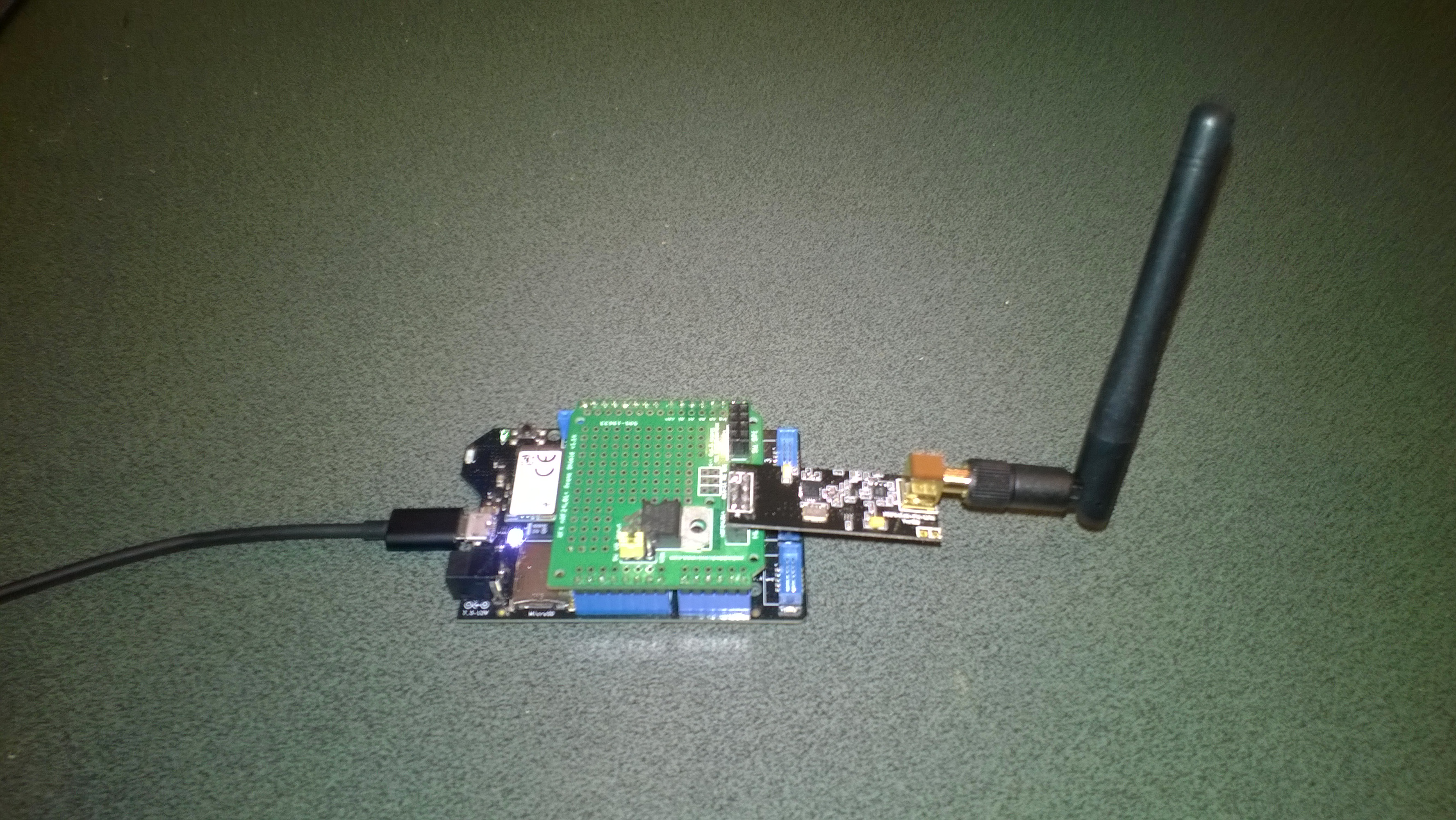
I’m using a Netduino 3 Wifi as the SPI port configuration means I can use a standard Arduino shield to connect up the NRF24L01 wireless module without any jumpers

Netduino 3 Wifi and embedded coolness shield

I have applied the PowerLevel fix from the TinyCLR and Meadow libraries but worry that there maybe other issues.

The thread '<No Name>' (0x2) has exited with code 0 (0x0).
Address: Dev01
PowerLevel: 2
IsAutoAcknowledge: True
Channel: 15
DataRate: 2
IsDynamicAcknowledge: False
IsDynamicPayload: True
IsEnabled: False
Frequency: 2415
IsInitialized: True
IsPowered: True
00:00:15-TX 9 byte message hello 255
Data Sent!
00:00:15-TX Succeeded!

Based on my experiences porting the library to three similar platforms and debugging it on two others I’m considering writing my own compile-time platform portable library.

nanoFramework nRF24L01 library Part1

After porting then debugging Windows 10 IoT Core, .NetMF, Wilderness Labs Meadow and GHI Electronics TinyCLR nRF24L01P libraries I figured yet another port, this time to a nanoFramework powered devices should be low risk.

My initial test rig uses a Netduino 3 Wifi and an Embedded Coolness nRF24 shield as I didn’t need to use jumper wires.

//---------------------------------------------------------------------------------
// Copyright (c) July 2020, devMobile Software
//
// Licensed under the Apache License, Version 2.0 (the "License");
// you may not use this file except in compliance with the License.
// You may obtain a copy of the License at
//
//     http://www.apache.org/licenses/LICENSE-2.0
//
// Unless required by applicable law or agreed to in writing, software
// distributed under the License is distributed on an "AS IS" BASIS,
// WITHOUT WARRANTIES OR CONDITIONS OF ANY KIND, either express or implied.
// See the License for the specific language governing permissions and
// limitations under the License.
//
//---------------------------------------------------------------------------------
#define NETDUINO3_WIFI   // nanoff --target NETDUINO3_WIFI --update

namespace devMobile.IoT.nRf24L01.ModuleSPI
{
   using System;
   using System.Threading;
   using System.Diagnostics;
   using System.Text;
   using Windows.Devices.Gpio;
   using Windows.Devices.Spi;

   public class Program
   {
      const byte SETUP_AW = 0x03;
      const byte RF_CH = 0x05;
      const byte RX_ADDR_P0 = 0x0A;
      const byte R_REGISTER = 0b00000000;
      const byte W_REGISTER = 0b00100000;
      const string P0_Address = "ZYXWV";

#if NETDUINO3_WIFI
      private const string SpiBusId = "SPI2";
#endif

      public static void Main()
      {
#if NETDUINO3_WIFI
         // Arduino D7->PD7
         int chipSelectPinNumber = PinNumber('A', 1);
#endif
         Debug.WriteLine("devMobile.IoT.nRf24L01.ModuleSPI starting");

         Debug.WriteLine(Windows.Devices.Spi.SpiDevice.GetDeviceSelector());

         try
         {
            GpioController gpioController = GpioController.GetDefault();

            var settings = new SpiConnectionSettings(chipSelectPinNumber)
            {
               ClockFrequency = 2000000,
               Mode = SpiMode.Mode0,
               SharingMode = SpiSharingMode.Shared,
            };

            using (SpiDevice device = SpiDevice.FromId(SpiBusId, settings))
            {
               Debug.WriteLine("nrf24L01Device Device...");
               if (device == null)
               {
                  Debug.WriteLine("nrf24L01Device == null");
               }

               Thread.Sleep(100);

               Debug.WriteLine("ConfigureSpiPort Done...");
               Debug.WriteLine("");

               Thread.Sleep(500);
               try
               {
                  // Read the Address width
                  Debug.WriteLine("Read address width");
                  byte[] txBuffer1 = new byte[] { SETUP_AW | R_REGISTER, 0x0 };
                  byte[] rxBuffer1 = new byte[txBuffer1.Length];

                  Debug.WriteLine(" nrf24L01Device.TransferFullDuplex...SETUP_AW");
                  Debug.WriteLine(" txBuffer:" + BitConverter.ToString(txBuffer1));
                  device.TransferFullDuplex(txBuffer1, rxBuffer1);
                  Debug.WriteLine(" rxBuffer:" + BitConverter.ToString(rxBuffer1));

                  // Extract then adjust the address width
                  byte addressWidthValue = rxBuffer1[1];
                  addressWidthValue &= 0b00000011;
                  addressWidthValue += 2;
                  Debug.WriteLine($"Address width 0x{SETUP_AW:x2} - Value 0X{rxBuffer1[1]:x2} Value adjusted {addressWidthValue}");
                  Debug.WriteLine("");

                  // Write Pipe0 Receive address
                  Debug.WriteLine($"Write Pipe0 Receive Address {P0_Address}");
                  byte[] txBuffer2 = new byte[addressWidthValue + 1];
                  byte[] rxBuffer2 = new byte[txBuffer2.Length];
                  txBuffer2[0] = RX_ADDR_P0 | W_REGISTER;
                  Array.Copy(Encoding.UTF8.GetBytes(P0_Address), 0, txBuffer2, 1, addressWidthValue);

                  Debug.WriteLine(" nrf24L01Device.Write...RX_ADDR_P0");
                  Debug.WriteLine(" txBuffer:" + BitConverter.ToString(txBuffer2));
                  device.TransferFullDuplex(txBuffer2, rxBuffer2);
                  Debug.WriteLine("");

                  // Read Pipe0 Receive address
                  Debug.WriteLine("Read Pipe0 Receive address");
                  byte[] txBuffer3 = new byte[addressWidthValue + 1];
                  txBuffer3[0] = RX_ADDR_P0 | R_REGISTER;
                  byte[] rxBuffer3 = new byte[txBuffer3.Length];

                  Debug.WriteLine(" nrf24L01Device.TransferFullDuplex...RX_ADDR_P0");
                  Debug.WriteLine(" txBuffer:" + BitConverter.ToString(txBuffer3));
                  device.TransferFullDuplex(txBuffer3, rxBuffer3);
                  Debug.WriteLine(" rxBuffer:" + BitConverter.ToString(rxBuffer3));
                  Debug.WriteLine($"Address 0x{RX_ADDR_P0:x2} Address {UTF8Encoding.UTF8.GetString(rxBuffer3, 1, addressWidthValue)}");
                  Debug.WriteLine("");

                  // Read the RF Channel
                  Debug.WriteLine("RF Channel read 1");
                  byte[] txBuffer4 = new byte[] { RF_CH | R_REGISTER, 0x0 };
                  byte[] rxBuffer4 = new byte[txBuffer4.Length];

                  Debug.WriteLine(" nrf24L01Device.TransferFullDuplex...RF_CH");
                  Debug.WriteLine(" txBuffer:" + BitConverter.ToString(txBuffer4));
                  device.TransferFullDuplex(txBuffer4, rxBuffer4);
                  Debug.WriteLine(" rxBuffer:" + BitConverter.ToString(rxBuffer4));

                  byte rfChannel1 = rxBuffer4[1];
                  Debug.WriteLine($"RF Channel 1 0x{RF_CH:x2} - Value 0X{rxBuffer4[1]:x2} - Value adjusted {rfChannel1+2400}");
                  Debug.WriteLine("");

                  // Write the RF Channel
                  Debug.WriteLine("RF Channel write");
                  byte[] txBuffer5 = new byte[] { RF_CH | W_REGISTER, rfChannel1+=1};
                  byte[] rxBuffer5 = new byte[txBuffer5.Length];

                  Debug.WriteLine(" nrf24L01Device.Write...RF_CH");
                  Debug.WriteLine(" txBuffer:" + BitConverter.ToString(txBuffer5));
                  //device.Write(txBuffer5);
                  device.TransferFullDuplex(txBuffer5, rxBuffer5);
                  Debug.WriteLine("");

                  // Read the RF Channel
                  Debug.WriteLine("RF Channel read 2");
                  byte[] txBuffer6 = new byte[] { RF_CH | R_REGISTER, 0x0 };
                  byte[] rxBuffer6 = new byte[txBuffer6.Length];

                  Debug.WriteLine(" nrf24L01Device.TransferFullDuplex...RF_CH");
                  Debug.WriteLine(" txBuffer:" + BitConverter.ToString(txBuffer6));
                  device.TransferFullDuplex(txBuffer6, rxBuffer6);
                  Debug.WriteLine(" rxBuffer:" + BitConverter.ToString(rxBuffer6));

                  byte rfChannel2 = rxBuffer6[1];
                  Debug.WriteLine($"RF Channel 2 0x{RF_CH:x2} - Value 0X{rxBuffer6[1]:x2} - Value adjusted {rfChannel2+2400}");
                  Debug.WriteLine("");
               }
               catch (Exception ex)
               {
                  Debug.WriteLine("Configure Port0 " + ex.Message);
               }
            }
         }
         catch (Exception ex)
         {
            Debug.WriteLine(ex.Message);
         }
      }

#if NETDUINO3_WIFI
      static int PinNumber(char port, byte pin)
      {
         if (port < 'A' || port > 'J')
            throw new ArgumentException();

         return ((port - 'A') * 16) + pin;
      }
#endif
   }
}

After bit of tinkering with SPI configuration options and checking device.Write vs. device.TransferFullDuplex usage. I can reliably read and write my nRF24L01 device’s receive port address and channel configuration.

devMobile.IoT.nRf24L01.ModuleSPI starting
SPI1,SPI2,SPI3,SPI4
nrf24L01Device Device...
ConfigureSpiPort Done...

Read address width
 nrf24L01Device.TransferFullDuplex...SETUP_AW
 txBuffer:03-00
 rxBuffer:0E-03
Address width 0x03 - Value 0X03 Value adjusted 5

Write Pipe0 Receive Address ZYXWV
 nrf24L01Device.Write...RX_ADDR_P0
 txBuffer:2A-5A-59-58-57-56

Read Pipe0 Receive address
 nrf24L01Device.TransferFullDuplex...RX_ADDR_P0
 txBuffer:0A-00-00-00-00-00
 rxBuffer:0E-5A-59-58-57-56
Address 0x0A Address ZYXWV

RF Channel read 1
 nrf24L01Device.TransferFullDuplex...RF_CH
 txBuffer:05-00
 rxBuffer:0E-02
RF Channel 1 0x05 - Value 0X02 - Value adjusted 2402

RF Channel write
 nrf24L01Device.Write...RF_CH
 txBuffer:25-03

RF Channel read 2
 nrf24L01Device.TransferFullDuplex...RF_CH
 txBuffer:05-00
 rxBuffer:0E-03
RF Channel 2 0x05 - Value 0X03 - Value adjusted 2403

The thread '<No Name>' (0x1) has exited with code 0 (0x0).
Done.

Next step is to port my TinyCLR nRF24L01 library which is based on the Techfoonina Windows 10 IoT Core port which is based on .NetMF library by Gralin.

Wireless field gateway Netduino client V2

This revised client is a Netduino V2Plus/V3 Ethernet/V3 Wifi device with a Silicon Labs SI7005 temperature & humidity sensor. These devices when used as sensor nodes can be battery powered and I use the Mac Address as the unique device identifier.

In this version of the protocol the message type & device identifier are nibbles packed into the first bye of the message. This saved a byte but limits the number of message types and device identifier length

//---------------------------------------------------------------------------------
// Copyright (c) 2018, devMobile Software
//
// Licensed under the Apache License, Version 2.0 (the "License");
// you may not use this file except in compliance with the License.
// You may obtain a copy of the License at
//
//     http://www.apache.org/licenses/LICENSE-2.0
//
// Unless required by applicable law or agreed to in writing, software
// distributed under the License is distributed on an "AS IS" BASIS,
// WITHOUT WARRANTIES OR CONDITIONS OF ANY KIND, either express or implied.
// See the License for the specific language governing permissions and
// limitations under the License.
//---------------------------------------------------------------------------------
using System;
using System.Net;
using System.Text;
using System.Threading;
using Microsoft.SPOT;
using Microsoft.SPOT.Hardware;
using Microsoft.SPOT.Net.NetworkInformation;
using devMobile.NetMF.Sensor;
using Gralin.NETMF.Nordic;
using SecretLabs.NETMF.Hardware.Netduino;

namespace devMobile.IoT.FIeldGateway.Netduino.Client
{
   class Client
   {
      private const byte nRF24Channel = 10;
      private const NRFDataRate nRF24DataRate = NRFDataRate.DR250kbps;
      private readonly byte[] nRF24ClientAddress = Encoding.UTF8.GetBytes("T&H01");
      private readonly byte[] nRF24BaseStationAddress = Encoding.UTF8.GetBytes("Base1");
      private static byte[] deviceIdentifier;
      private readonly OutputPort led = new OutputPort(Pins.ONBOARD_LED, false);
      private readonly NRF24L01Plus radio;
      private readonly SiliconLabsSI7005 sensor = new SiliconLabsSI7005();

      public Client()
      {
         radio = new NRF24L01Plus();
      }

      public void Run()
      {
         // Configure the nRF24 hardware
         radio.OnDataReceived += OnReceive;
         radio.OnTransmitFailed += OnSendFailure;
         radio.OnTransmitSuccess += OnSendSuccess;

         radio.Initialize(SPI.SPI_module.SPI1, Pins.GPIO_PIN_D7, Pins.GPIO_PIN_D3, Pins.GPIO_PIN_D2);
         radio.Configure(nRF24ClientAddress, nRF24Channel, nRF24DataRate);
         radio.Enable();

         // Setup the device unique identifer, in this case the hardware MacAddress
         deviceIdentifier = NetworkInterface.GetAllNetworkInterfaces()[0].PhysicalAddress;
         Debug.Print(" Device Identifier : " + BytesToHexString(deviceIdentifier));

         Timer humidityAndtemperatureUpdates = new Timer(HumidityAndTemperatureTimerProc, null, 15000, 15000);

         Thread.Sleep(Timeout.Infinite);
      }

          private void HumidityAndTemperatureTimerProc(object state)
      {
         led.Write(true);

         double humidity = sensor.Humidity();
         double temperature = sensor.Temperature();

         Debug.Print("H:" + humidity.ToString("F1") + " T:" + temperature.ToString("F1"));
         string values = "T " + temperature.ToString("F1") + ",H " + humidity.ToString("F0");

         // Stuff the single byte header ( payload type nibble & deviceIdentifierLength nibble ) + deviceIdentifier into first byte of payload
         byte[] payload = new byte[ 1 + deviceIdentifier.Length + values.Length];
         payload[0] =  (byte)((1 <> 4];

            // Mask off the upper 4 bits to get the rest of it.
            hexString += hexChars[bytes[b] & 0x0F];
         }

         return hexString;
      }
   }
}

Bill of materials (prices as at March 2018)

Wireless field gateway Netduino client V1

This client is a Netduino V2Plus/V3 Ethernet/V3 Wifi device with a Silicon Labs SI7005 temperature & humidity sensor. These devices when used as sensor nodes can be battery powered and I use the Mac Address as the unique device identifier.

Reducing the power consumption, improving reliability etc. will be covered in future posts

//---------------------------------------------------------------------------------
// Copyright (c) 2017, devMobile Software
//
// Licensed under the Apache License, Version 2.0 (the "License");
// you may not use this file except in compliance with the License.
// You may obtain a copy of the License at
//
//     http://www.apache.org/licenses/LICENSE-2.0
//
// Unless required by applicable law or agreed to in writing, software
// distributed under the License is distributed on an "AS IS" BASIS,
// WITHOUT WARRANTIES OR CONDITIONS OF ANY KIND, either express or implied.
// See the License for the specific language governing permissions and
// limitations under the License.
//---------------------------------------------------------------------------------
using System;
using System.Net;
using System.Text;
using System.Threading;
using Microsoft.SPOT;
using Microsoft.SPOT.Hardware;
using Microsoft.SPOT.Net.NetworkInformation;
using devMobile.NetMF.Sensor;
using Gralin.NETMF.Nordic;
using SecretLabs.NETMF.Hardware.Netduino;

namespace devMobile.IoT.FIeldGateway.Netduino.Client
{
   class Client
   {
      private const byte nRF24Channel = 10;
      private const NRFDataRate nRF24DataRate = NRFDataRate.DR250kbps;
      private readonly byte[] nRF24ClientAddress = Encoding.UTF8.GetBytes("TandH");
      private readonly byte[] nRF24BaseStationAddress = Encoding.UTF8.GetBytes("Base1");
      private static byte[] deviceIdentifier;
      private readonly OutputPort led = new OutputPort(Pins.ONBOARD_LED, false);
      private readonly NRF24L01Plus radio;
      private readonly SiliconLabsSI7005 sensor = new SiliconLabsSI7005();

      public Client()
      {
         radio = new NRF24L01Plus();
      }

      public void Run()
      {
         // Configure the nRF24 hardware
         radio.OnDataReceived += OnReceive;
         radio.OnTransmitFailed += OnSendFailure;
         radio.OnTransmitSuccess += OnSendSuccess;

         radio.Initialize(SPI.SPI_module.SPI1, Pins.GPIO_PIN_D7, Pins.GPIO_PIN_D3, Pins.GPIO_PIN_D2);
         radio.Configure(nRF24ClientAddress, nRF24Channel, nRF24DataRate);
         radio.Enable();

         // Setup the device unique identifer, in this case the hardware MacAddress
         deviceIdentifier = NetworkInterface.GetAllNetworkInterfaces()[0].PhysicalAddress;
         Debug.Print(" Device Identifier : " + BytesToHexString(deviceIdentifier));

         Timer humidityAndtemperatureUpdates = new Timer(HumidityAndTemperatureTimerProc, null, 15000, 15000);

         Thread.Sleep(Timeout.Infinite);
      }

      private void HumidityAndTemperatureTimerProc(object state)
      {
         led.Write(true);

         double humidity = sensor.Humidity();
         double temperature = sensor.Temperature();

         Debug.Print("H:" + humidity.ToString("F1") + " T:" + temperature.ToString("F1"));
         string values = "T " + temperature.ToString("F1") + ",H " + humidity.ToString("F0");

         // Stuff the 2 byte header ( payload type & deviceIdentifierLength ) + deviceIdentifier into payload
         byte[] payload = new byte[1 + 1 + deviceIdentifier.Length + values.Length];
         payload[0] = 1;
         payload[1] = (byte)deviceIdentifier.Length;
         Array.Copy(deviceIdentifier, 0, payload, 2, deviceIdentifier.Length);

         Encoding.UTF8.GetBytes( values, 0, values.Length, payload, 8 ) ;

         radio.SendTo(nRF24BaseStationAddress, payload );
      }

      private void OnSendSuccess()
      {
         led.Write(false);

         Debug.Print("Send Success!");
      }

      private void OnSendFailure()
      {
         Debug.Print("Send failed!");
      }

      private void OnReceive(byte[] data)
      {
         led.Write(!led.Read());

         string message = new String(Encoding.UTF8.GetChars(data));

         Debug.Print("Receive " + message); ;
      }

      private static string BytesToHexString(byte[] bytes)
      {
         string hexString = string.Empty;

         // Create a character array for hexidecimal conversion.
         const string hexChars = "0123456789ABCDEF";

         // Loop through the bytes.
         for (byte b = 0; b < bytes.Length; b++)          {             if (b > 0)
               hexString += "-";

            // Grab the top 4 bits and append the hex equivalent to the return string.
            hexString += hexChars[bytes[b] >> 4];

            // Mask off the upper 4 bits to get the rest of it.
            hexString += hexChars[bytes[b] & 0x0F];
         }

         return hexString;
      }
   }

.Net Micro framework Deployment Tool output

WindowsIoTCentralNetduinoClient

Raspberry PI UWP application output

Interrupt Triggered: FallingEdge
11:40:46 Address 5C-86-4A-00-E4-1D Length 6 Payload T 25.2,H 90 Length 11
 Sensor 5C-86-4A-00-E4-1D-T Value 25.2
 Sensor 5C-86-4A-00-E4-1D-H Value 90
Interrupt Triggered: RisingEdge
Interrupt Triggered: FallingEdge
11:41:01 Address 5C-86-4A-00-E4-1D Length 6 Payload T 25.3,H 91 Length 11
 Sensor 5C-86-4A-00-E4-1D-T Value 25.3
 Sensor 5C-86-4A-00-E4-1D-H Value 91
Interrupt Triggered: RisingEdge
Interrupt Triggered: FallingEdge
11:41:16 Address 5C-86-4A-00-E4-1D Length 6 Payload T 25.3,H 90 Length 11
 Sensor 5C-86-4A-00-E4-1D-T Value 25.3
 Sensor 5C-86-4A-00-E4-1D-H Value 90
Interrupt Triggered: RisingEdge
Interrupt Triggered: FallingEdge
11:41:31 Address 5C-86-4A-00-E4-1D Length 6 Payload T 25.3,H 90 Length 11
 Sensor 5C-86-4A-00-E4-1D-T Value 25.3
 Sensor 5C-86-4A-00-E4-1D-H Value 90
Interrupt Triggered: RisingEdge
Interrupt Triggered: FallingEdge
11:41:46 Address 5C-86-4A-00-E4-1D Length 6 Payload T 25.3,H 90 Length 11
 Sensor 5C-86-4A-00-E4-1D-T Value 25.3
 Sensor 5C-86-4A-00-E4-1D-H Value 90
Interrupt Triggered: RisingEdge

Bill of materials (prices as at Jan 2018)

nRF24 Windows 10 IoT Core reboot

My first live deployment of the nRF24L01 Windows 10 IoT Core field gateway is now scheduled for mid Q1 2018 so time for a reboot. After digging out my Raspbery PI 2/3 devices and the nRF24L01+ shield (with modifications detailed here) I have a basic plan with some milestones.

My aim is to be able to wirelessly acquire data from several dozen Arduino, devduino, seeeduino, and Netduino devices, Then, using a field gateway on a Raspberry PI running Windows 10 IoT Core upload it to Microsoft IoT Central

First bit of code – Bleepy a simple background application to test the piezo beeper on the RPI NRF24 Shield

namespace devmobile.IoTCore.Bleepy
{
   public sealed class StartupTask : IBackgroundTask
   {
      private BackgroundTaskDeferral deferral;
      private const int ledPinNumber = 4;
      private GpioPin ledGpioPin;
      private ThreadPoolTimer timer;

      public void Run(IBackgroundTaskInstance taskInstance)
      {
         var gpioController = GpioController.GetDefault();
         if (gpioController == null)
         {
            Debug.WriteLine("GpioController.GetDefault failed");
            return;
         }

         ledGpioPin = gpioController.OpenPin(ledPinNumber);
         if (ledGpioPin == null)
         {
            Debug.WriteLine("gpioController.OpenPin failed");
            return;
         }

         ledGpioPin.SetDriveMode(GpioPinDriveMode.Output);

         this.timer = ThreadPoolTimer.CreatePeriodicTimer(Timer_Tick, TimeSpan.FromMilliseconds(500));

         deferral = taskInstance.GetDeferral();

         Debug.WriteLine("Rum completed");
      }

      private void Timer_Tick(ThreadPoolTimer timer)
      {
         GpioPinValue currentPinValue = ledGpioPin.Read();

         if (currentPinValue == GpioPinValue.High)
         {
            ledGpioPin.Write(GpioPinValue.Low);
         }
         else
         {
            ledGpioPin.Write(GpioPinValue.High);
         }
      }
   }
}

Note the blob of blu tack over the piezo beeper to mute noise
nRF24ShieldMuted

Netduino 3 Wifi xively nRF24L01 Gateway

The first version of this code acquired data from a number of *duino devices and uploaded it to xively for a week without any problems(bar my ADSL modem dropping out every so often which it recovered from without human intervention). The data streams are the temperature and humidity for the three bedrooms in my house (the most reliable stream is Bedroom 1). Next version will use the new Netduino.IP stack and run on a Netduino 2 Plus

Netduino 3 Wifi with nRF24L01 shield

Netduino 3 Wifi + nRF24L01 shield

To make the software easy to setup all the gateway configuration is stored on a MicroSD and can be modified with a text editor. When the application starts it looks for a file in the root directory of the MicroSD card called app.config. If the file does not exist an empty template is created.

httprequestreadwritetimeoutmsec=2500
httprequesttimeoutmsec=2500
webproxyaddress=
webproxyport=
xivelyapibaseurl=http://api.xively.com/v2/feeds/
xivelyapikey=XivelyAPIKeyGoesHere
xivelyapifeedid=XivelyFeedIDGoesHere
xivelyapicontenttype=text/csv
xivelyapiendpoint=.csv
nrf2l01address=AddressGoesHere
nrf2l01channel=ChannelGoesHere
nrf2l01datarate=0
channel1=Sensor1
channel2=Sensor2
channel3=Sensor3
channel4=Sensor4
channel5=Sensor5
...
...

The first byte of each (upto 32 byte) nRF24L01 message is used to determine the Xively channel.

For testing I used a simple *duino program which uploads temperature and humidity readings every 5 seconds. It’s not terribly efficient or elegant and is just to illustrate how to package up the data.

#include <RF24_config>
#include <nRF24L01.h>
#include <SPI.h>
#include <RF24.h>
#include "Wire.h"
#include <TH02_dev.h>

//UNO R3 with embedded coolness board
//RF24 radio(3, 7);
//devDuino  with onboard
RF24 radio(8, 7);

char payload[32] = "";
const uint64_t pipe = 0x3165736142LL; // Base1 pay attention to byte ordering and address length

void setup()
{
  Serial.begin(9600);

  radio.begin();
  radio.setPALevel(RF24_PA_MAX);
  radio.setChannel(10);
  radio.enableDynamicPayloads();
  radio.openWritingPipe(pipe);

  radio.printDetails();

  /* Power up,delay 150ms,until voltage is stable */
  delay(150);

  TH02.begin();

  delay(1000);
}

void loop()
{
  float temperature = TH02.ReadTemperature();
  float humidity = TH02.ReadHumidity();

  radio.powerUp();

  payload[0] = 'A';
  dtostrf(temperature, 5, 1, &payload[1]);
  Serial.println(payload);
  boolean result = radio.write(payload, strlen(payload));
  if (result)
    Serial.println("T Ok...");
  else
    Serial.println("T failed.");

  payload[0] = 'B';
  dtostrf(humidity, 5, 1, &payload[1]);
  Serial.println(payload);
  result = radio.write(payload, strlen(payload));
  if (result)
    Serial.println("H Ok...");
  else
    Serial.println("H failed.");

  radio.powerDown();

  delay(5000);
}

The gateway code creates a thread for each call to the Xively REST API. (In future the code may need to limit the number of concurrent requests)

private void OnReceive(byte[] data)
{
   activityLed.Write(!activityLed.Read());

   // Ensure that we have a valid payload
   if ( data.Length == 0 )
   {
      Debug.Print( "ERROR - Message has no payload" ) ;
      return ;
   }

   // Extract the device id
   string deviceId = xivelyApiChannleIDPrefix + data[0].ToString();
   string message = new String(Encoding.UTF8.GetChars(data, 1, data.Length - 1));

   string xivelyApiChannel = appSettings.GetString( deviceId, string.Empty ) ;
   if ( xivelyApiChannel.Length == 0 )
   {
      Debug.Print("ERROR - Inbound message has unknown channel " + deviceId);
      return ;
   }
   Debug.Print(DateTime.Now.ToString("HH:mm:ss") + " " + xivelyApiChannel + " " + message); ;

   Thread thread = new Thread(() =&gt; xivelyFeedUpdate(xivelyApiChannel, message ));
   thread.Start();
   }

private void xivelyFeedUpdate( string channel, string value)
{
   #region Assertions
   Debug.Assert(channel != null);
   Debug.Assert(channel != string.Empty );
   Debug.Assert(value != null);
   #endregion

   try
   {
      WebProxy webProxy = null;

      if (webProxyAddress.Length &gt; 1)
      {
         webProxy = new WebProxy(webProxyAddress, webProxyPort);
      }

      using (HttpWebRequest request = (HttpWebRequest)WebRequest.Create(xivelyApiBaseUrl + xivelyApiFeedID + xivelyApiEndpoint))
      {
         byte[] buffer = Encoding.UTF8.GetBytes(channel + "," + value);

         DateTime httpRequestedStartedAtUtc = DateTime.UtcNow;

         if (webProxy != null)
         {
            request.Proxy = webProxy;
         }
         request.Method = "PUT";
         request.ContentLength = buffer.Length;
         request.ContentType = xivelyApiContentType;
         request.Headers.Add("X-ApiKey", xivelyApiKey);
         request.KeepAlive = false;
         request.Timeout = httpRequestTimeoutmSec;
         request.ReadWriteTimeout = httpRequestReadWriteTimeoutmSec;

         // request body
         Debug.Print("HTTP request");
         using (Stream stream = request.GetRequestStream())
         {
            stream.Write(buffer, 0, buffer.Length);
         }

         using (var response = (HttpWebResponse)request.GetResponse())
         {
            Debug.Print(" Status: " + response.StatusCode + " : " + response.StatusDescription);
         }

         TimeSpan duration = DateTime.UtcNow - httpRequestedStartedAtUtc;
         Debug.Print(" Duration: " + duration.ToString());
      }
   }
   catch (Exception ex)
   {
      Debug.Print(ex.Message);
   }
}

To use this code download the Nordic nRF24L01 library from Codeplex then include that plus my Netduino NRF24L01 Xively Gateway in a new solution and it should just work.

Deploy the application to a Netduino 2 Plus or Netduino 3 Wifi device and run it to create the app.config file, then use a text editor to update the file with your Xively & device settings.

I’ll upload this and a couple of other projects to GitHub shortly.

Bill of materials (prices as at July 2015)

Netduino 3 Wifi xively nRF24L01 Gateway introduction

Around home I have a number of Arduino, devDuino and Netduino devices collecting power consumption, temperature & humidity measurements. Previously I had built an Azure event hub gateway which runs on Windows 7(or later) which acts as a gateway forwarding local http requests to an Microsoft Azure event hub.

Not all my embedded devices are capable of making an http request but an nRF24l01 based approach is supported.

For this application I wanted something a bit simpler than an Azure Event hub which could plot basic graphs and as I didn’t require massive scale Xively looked ideal.

Netduino 3 Wifi xively gateway + duino clients

Netduino 3 Wifi xively gateway and *duino clients

Over the next few blog postings I will show how I built the Netduino 3 wifi application and the Arduino based clients.

Bill of materials for the Xively gateway (prices at June 2015)

First step is to configure the network

NetworkInterface networkInterface = NetworkInterface.GetAllNetworkInterfaces()[0];

if (networkInterface.IsDhcpEnabled)
{
   Debug.Print(" Waiting for IP address ");

   while (NetworkInterface.GetAllNetworkInterfaces()[0].IPAddress == IPAddress.Any.ToString()) 
   {
      Thread.Sleep(100);
   }
}

// Display network config for debugging
Debug.Print("Network configuration");
Debug.Print(" Network interface type: " + networkInterface.NetworkInterfaceType.ToString());
Debug.Print(" MAC Address: " + BytesToHexString(networkInterface.PhysicalAddress));
Debug.Print(" DHCP enabled: " + networkInterface.IsDhcpEnabled.ToString());
Debug.Print(" Dynamic DNS enabled: " + networkInterface.IsDynamicDnsEnabled.ToString());
Debug.Print(" IP Address: " + networkInterface.IPAddress.ToString());
Debug.Print(" Subnet Mask: " + networkInterface.SubnetMask.ToString());
Debug.Print(" Gateway: " + networkInterface.GatewayAddress.ToString());

foreach (string dnsAddress in networkInterface.DnsAddresses)
{
   Debug.Print(" DNS Server: " + dnsAddress.ToString());
}

_module = new NRF24L01Plus();

Then setup the nRF24l01 driver

_module.OnDataReceived += OnReceive;
_module.OnTransmitFailed += OnSendFailure;
_module.OnTransmitSuccess += OnSendSuccess;

_module.Initialize(SPI.SPI_module.SPI1, Pins.GPIO_PIN_D7, Pins.GPIO_PIN_D3, Pins.GPIO_PIN_D2);
_module.Configure(myAddress, channel, NRFDataRate.DR1Mbps);
_module.Enable();

The setup required for the Xively API and mapping the devices highlighted the need for a means of storing configuration which could be modified using a simple text editor.

Netduino 3 Wifi with nRF24L01 shield

Netduino 3 Wifi + nRF24L01 shield

This software was built using tooling created and shared by others.

Big thanks to

Jakub Bartkowiak – Gralin.NETMF.Nordic.NRF24L01Plus

CodeClub Internet of Things Boxes sponsored by Microsoft NZ

A few months ago Microsoft NZ donated NZ6K to CodeClub NZ for the purchase of kits for our basic electronics and programming classes.

Over the last couple of months I have been assembling these so we now have 15 kits ready to go. Each one has enough gear for 2-6 students, fits into a 7L Sistema plastic box and contains the following items

2 x Netduino 2 Plus devices
2 x Seeedstudio Grove Starter kits for Arduino which contain

  • 1xBase Shield
  • 1xGrove – LCD RGB Backlight
  • 1xGrove – Smart Relay
  • 1xGrove – Buzzer
  • 1xGrove – Sound Sensor
  • 1xGrove – Touch Sensor
  • 1xGrove – Rotary Angle Sensor
  • 1xGrove – Temperature Sensor
  • 1xGrove – Light Sensor
  • 1xGrove – Button
  • 1xGrove LED Blue-Blue
  • 1xGrove LED Green-Green
  • 1xGrove  LED Red-Red
  • 1xMini Servo
  • 10xGrove Cables
  • 1x9V to Barrel Jack Adapter
  • 1xGrove starter kit Manual
  • 1xGreen Plastic Box
  • 1 x ultrasonic ranger

In addition to the Netduino devices and the Grove starter kits, we also include

Thanks to Embedded coolness, Secret Labs, and Seeedstudio which discounted their products so our funding went further.

CodeClub Programming and electronics kits

CodeClub Programming and electronics kits

Netduino Crazyflie Wii Nunchuk Remote Control V1.0

After flying the Crazyflie for a couple of days with the Joystick shield based remote control I figured an alternate user interface based on a Wii Nunchuk could be interesting. (It might also make the Crazyflie easier to operate for novice pilots). After a couple of hours coding I have a proof of concept Netduino based Crazyflie Nanocopter Wii Nunchck remote control unit.

Initially the nanocopter was difficult to fly, bouncing up and down (thrust control issues) and swaying side to side (roll & pitch control issues). After some digging I found that every so often the Wii nunchuk (my cheap clone) would return a buffer full of 0xFF or 0x00 bytes.  The 0xFF case had been handled but not the 0x00 one. I added a second test into the GetData  method (around line 335) to catch the 0x00 scenario and this appeared to fix the problem.

cnt = 0;
for (int i = 0; i &lt; inputBuffer.Length; i++)
   if (inputBuffer[i] == 0x0) cnt++;
if (cnt == inputBuffer.Length)
{
   return false;
}

CrazyFlie Netduino Wiichuck based Remote

CrazyFlie Netduino Wiichuck based Remote

Bill on Materials (Prices as at Jan 2014)

This software was built using tooling created and shared by others.

Big thanks to

Jakub Bartkowiak – Gralin.NETMF.Nordic.NRF24L01Plus

Szymon Kobalczyk – Wiichuck I2C driver

Antao Almada – HydraMF.BitConverter

The nunchuck accelerometer provides roll and pitch, the joystick is for thrust and yaw. The first version of the CrazyFlieWiiChuckV1.0 is pretty basic and I have intentionally reduced the maximum roll, pitch, thrust and yaw values to make it easier to fly. (Need to set the Grove Base Shield to 3V3 for my code to work)

Currently I only calculate offset values for thrust & yaw. After a couple of test flights some visual indication of the pitch and roll values from the nunchuk would be helpfull.

Netduino Crazyflie Joystick Shield Remote Control V1.0

Sometimes you start with a goal in mind then a couple of days later you have built something interesting but totally unrelated to what you originally intended to do….

I have several devices (both Netduino & Arduino) which I want to use to collect and upload data to the cloud so I can monitor the resource usage of my house.

I had read Clemens Vaster post on Service Assisted Communication and I was planning to use a Windows Server Essentials 2012 box I have running 24/7 in the hallway to forward updates to the cloud.

I wanted to connect the remote data acquisition nodes directly to the server using their baked in nRF24L01+ support. On the server end the Crazyradio 2.4 Hhz nRF24LU1 USB dongle looked ideal. After some initial positive results I found that the CrazyRadio firmware had been implemented in a way that made it not suitable for my application. (I even considered downloading the BitCraze development VM and building my own custom firmware)

After spending a few hours trying to get the CrazyRadio dongle working I looked at my Crazyflie Nano QuadCopter sitting on the bookshelf.

Then I realised what I really needed is a more portable Crazyflie remote control unit so I didn’t have to unpack my laptop. So two nights later I have a proof of concept Netduino based Crazyflie Nanocopter remote control unit.

CrazyFlie nano copter and Netduino Based Remote

CrazyFlie Netduino based Remote

Bill on Materials (Prices as at Jan 2014)

This software was built using tooling created and shared by others.

Big thanks to

Jakub Bartkowiak – Gralin.NETMF.Nordic.NRF24L01Plus

Antao Almada – HydraMF.BitConverter

Mike McCauley – NRF24 library for Arduino.

I used the NRF24 CrazyFlie emulator to debug my project. No doubt stopping me crashing my Crazyflie many times while debugging.

The Joystick shield has to be modified to work with the common Netduino nRF24L01 libraries which use interrupts rather than polling.

The joystick on the shield is for roll and pitch, the external joystick is for thrust and yaw. The first version of the JoystickShieldnRF24l01V1.0 is pretty basic but I’ll try and enhance it over the next couple of posts.