Random wanderings through Microsoft Azure esp. PaaS plumbing, the IoT bits, AI on Micro controllers, AI on Edge Devices, .NET nanoFramework, .NET Core on *nix and ML.NET+ONNX
While trying to debug a deadlock in my RFM69 library I noticed in the logging that I was getting a receive interrupt while putting bytes in the FIFO for transmission.
Register 0x49 - Value 0X00 - Bits 00000000
Register 0x4a - Value 0X00 - Bits 00000000
Register 0x4b - Value 0X00 - Bits 00000000
Register 0x4c - Value 0X00 - Bits 00000000
Register 0x4d - Value 0X00 - Bits 00000000
...
22:58:47.192 Received To 0X22 a 33 byte message hello world RFM69-915-02 10-58-47 CRC Ok True
The thread 0x6a8 has exited with code 0 (0x0).
22:58:48.334 Send-hello world RFM69-915-01 10-58-48
22:58:48.351 Send-Done
22:58:48.388 Received To 0X22 a 33 byte message hello world RFM69-915-02 10-58-52 CRC Ok True
22:58:48.462 Transmit-Done
The thread 0xde4 has exited with code 0 (0x0).
22:58:53.427 Send-hello world RFM69-915-01 10-58-53
22:58:53.445 Send-Done
22:58:53.556 Transmit-Done
22:58:57.382 Received To 0X22 a 33 byte message hello world RFM69-915-02 10-58-57 CRC Ok True
The thread 0x17c has exited with code 0 (0x0).
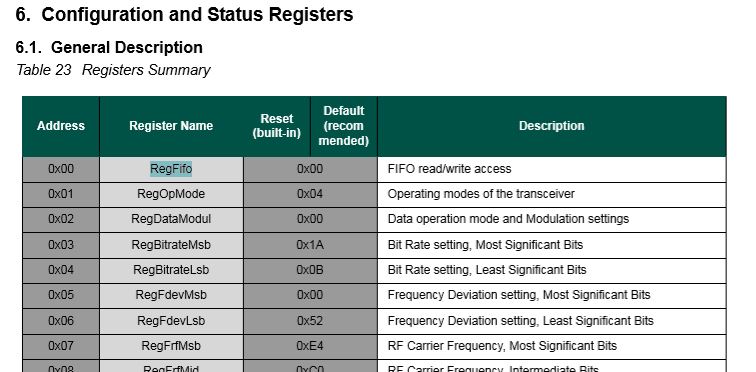
After re-reading the RFM69CW/RFM69HCW module datasheet (based on the Semtech SX1231/SX1231H) I realised my code for loading the FIFO could be more efficient.
SX1231 Register map FIFO
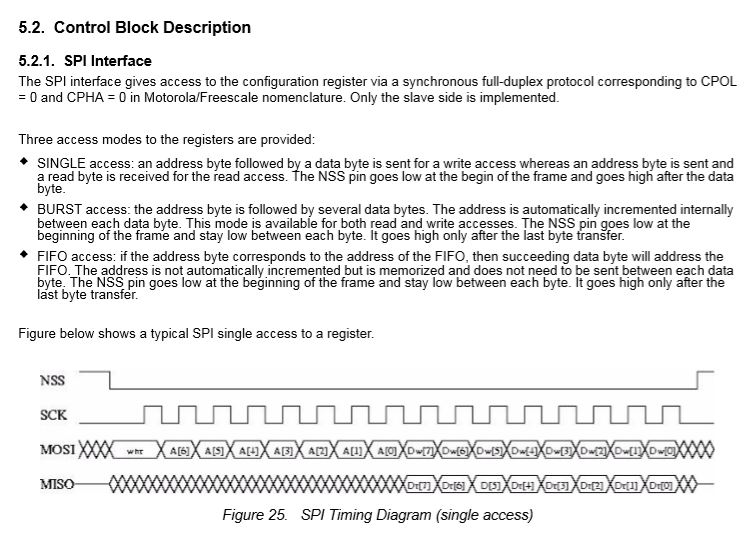
Based on the timing diagram I could remove the loop which loads bytes in the FIFO for transmission.
After stress testing with several client devices this appears to have reduced the scope of a receive interrupt to occur while a packet was being loaded into the FIFO for transmission. I now need to dig deeper into the timing around entering different operational modes and selectively enabling event interrupts.
After problems with interleaved interrupt handling in my Windows 10 IoT Core client I figured the AutoMode used by the plainRFM69 library might be worth investigation. My first Arduino client was based on the plainRFM69 library but had Interoperability issues.
For this attempt I also started with the minimal sample and modified the code to send and receive text messages.
/*
    Copyright (c) 2014, Ivor Wanders, Bryn Lewis 2019
    MIT License, see the LICENSE.md file in the root folder.
*/

#include <SPI.h>
#include <plainRFM69.h>

// slave select pin.
#define SLAVE_SELECT_PIN 10

// connected to the reset pin of the RFM69.
#define RESET_PIN 9

// tie this pin down on the receiver.
#define SENDER_DETECT_PIN A0

const uint8_t tx_buffer[] = "ABCDEFGHIJKLMNOPQRSTURWXYZ1234567890";
//const uint8_t tx_buffer[] = "abcdefghijklmnopqrstuvwxyz1234567890";
uint8_t rx_buffer[sizeof(tx_buffer)] = "";

plainRFM69 rfm = plainRFM69(SLAVE_SELECT_PIN);


void sender() {

  uint32_t start_time = millis();

  uint32_t counter = 1; // the counter which we are going to send.

  while (true) {
    rfm.poll(); // run poll as often as possible.

    if (!rfm.canSend()) {
      continue; // sending is not possible, already sending.
    }

    if ((millis() - start_time) > 1000) { // every 500 ms.
      start_time = millis();

      // be a little bit verbose.
      Serial.print("Send:"); Serial.println(counter);

      // send the number of bytes equal to that set with setPacketLength.
      // read those bytes from memory where counter starts.
      rfm.sendVariable(tx_buffer, counter);

      counter++; // increase the counter.

      if ( counter > strlen(tx_buffer))
      {
        counter = 1;
      }
    }
  }
}

void receiver() {
  uint32_t counter = 0; // to count the messages.

  while (true) {

    rfm.poll(); // poll as often as possible.

    while (rfm.available())
    {
      uint8_t len = rfm.read(rx_buffer); // read the packet into the new_counter.

      // print verbose output.
      Serial.print("Packet Len:");
      Serial.print( len );
      Serial.print(" : ");
      Serial.println((char*)rx_buffer);
    }
  }
}

void setup() {
  Serial.begin(9600);
  SPI.begin();

  bareRFM69::reset(RESET_PIN); // sent the RFM69 a hard-reset.

  //rfm.setRecommended(); // set recommended paramters in RFM69.
  rfm.setPacketType(true, false); // set the used packet type.

  rfm.setBufferSize(2);   // set the internal buffer size.
  rfm.setPacketLength(sizeof(rx_buffer)); // set the packet length.

  rfm.setFrequency((uint32_t)909560000); // set the frequency.

  rfm.setLNA(RFM69_LNA_IMP_200OHM, RFM69_LNA_GAIN_AGC_LOOP);

  // p71, 3 preamble bytes.
  rfm.setPreambleSize(16);

  // p71, 4 bytes sync of 0x01, only start listening when sync is matched.
  //uint8_t syncthing[] = {0xaa, 0x2d, 0xd4};
  uint8_t syncthing[] = {0xd4, 0x2d, 0xaa};
  rfm.setSyncConfig(true, false, sizeof(syncthing), 0);
  rfm.setSyncValue(&syncthing, sizeof(syncthing));

  rfm.dumpRegisters(Serial);

  // baudrate is default, 4800 bps now.

  rfm.receive();
  // set it to receiving mode.

  pinMode(SENDER_DETECT_PIN, INPUT_PULLUP);
  delay(5);
}

void loop() {
  if (digitalRead(SENDER_DETECT_PIN) == LOW) {
    Serial.println("Going Receiver!");
    receiver();
    // this function never returns and contains an infinite loop.
  } else {
    Serial.println("Going sender!");
    sender();
    // idem.
  }
}
I took the list register values and loaded them into a Excel spreadsheet alongside the values from my Windows 10 IoT Core application
First thing I noticed was the order of the three sync byes (Registers 0x2F, 0x30, 0x31) was reversed. I then modified the run method in the Windows 10 code so the registers settings on both devices matched. (I removed the PlainRFM69 SetRecommended call so as many of the default options as possible were used).
I also found an error with the declaration of the RegPacketConfig1DcFree enumeration (Whitening = 0b0100000 vs. Whitening = 0b01000000) which wouldn’t have helped.
Register 0x4c - Value 0X00 - Bits 00000000
Register 0x4d - Value 0X00 - Bits 00000000
...
17:55:53.559 Received 1 byte message A CRC Ok True
.17:55:54.441 Received 2 byte message AB CRC Ok True
.17:55:55.444 Received 3 byte message ABC CRC Ok True
.17:55:56.447 Received 4 byte message ABCD CRC Ok True
.17:55:57.449 Received 5 byte message ABCDE CRC Ok True
.17:55:58.453 Received 6 byte message ABCDEF CRC Ok True
The thread 0x578 has exited with code 0 (0x0).
.17:55:59.622 Received 7 byte message ABCDEFG CRC Ok True
.17:56:00.457 Received 8 byte message ABCDEFGH CRC Ok True
.17:56:01.460 Received 9 byte message ABCDEFGHI CRC Ok True
.17:56:02.463 Received 10 byte message ABCDEFGHIJ CRC Ok True
..17:56:03.955 Received 11 byte message ABCDEFGHIJK CRC Ok True
17:56:04.583 Received 12 byte message ABCDEFGHIJKL CRC Ok True
I did some investigation into that the plainRMF69 code and found the ReadMultiple and WriteMuliple methods reverse the byte order
void bareRFM69::writeMultiple(uint8_t reg, void* data, uint8_t len){
    SPI.beginTransaction(SPISettings(10000000, MSBFIRST, SPI_MODE0));  // gain control of SPI bus
    this->chipSelect(true); // assert chip select
    SPI.transfer(RFM69_WRITE_REG_MASK | (reg & RFM69_READ_REG_MASK));
    uint8_t* r = reinterpret_cast<uint8_t*>(data);
    for (uint8_t i=0; i < len ; i++){
        SPI.transfer(r[len - i - 1]);
    }
    this->chipSelect(false);// deassert chip select
    SPI.endTransaction();    // release the SPI bus
}

void bareRFM69::readMultiple(uint8_t reg, void* data, uint8_t len){
    SPI.beginTransaction(SPISettings(10000000, MSBFIRST, SPI_MODE0));  // gain control of SPI bus
    this->chipSelect(true); // assert chip select

    SPI.transfer((reg % RFM69_READ_REG_MASK));
    uint8_t* r = reinterpret_cast<uint8_t*>(data);
    for (uint8_t i=0; i < len ; i++){
        r[len - i - 1] = SPI.transfer(0);
    }
    this->chipSelect(false);// deassert chip select
    SPI.endTransaction();    // release the SPI bus
}
I won’t be able to use interrupt AutoMode clients with the EasySensors shields as the DIO2 pin is not connected but on the AdaFruit RFM69HCW Radio Bonnet 433MHz or 915MHz it is connected to GPIO24.
While doing yet more stress testing I noticed a couple of odd message go past and a long pause every so often when sending a message in the Visual Studio output window.
I have two Arduino devices sending addressed messages every (both individual and broadcast) to the Adafruit RFM69 HCW Radio Bonnet, on my two Windows 10 IoT Core devices every 100mSec. At the same time the windows 10 devices are sending each other a message every 5 seconds.
To help spot the pauses I added some code to mark any events where there was a significant gap. In this case ” is ASCII character for 0x22 the device address
21:10:30.746 Received To 34 a 23 byte message Hello World ---0x22:236 CRC Ok True
21:10:30.918 Received To 153 a 23 byte message Hello World ---0x99:236 CRC Ok True
21:10:31.399 Received To 34 a 23 byte message Hello World ---0x22:237 CRC Ok True
21:10:31.568 Send-hello world RFM69-915-01 09-10-31
21:10:31.580 Send-Done
21:10:31.592 Received To 34 a 33 byte message """"""""""""""""""""""""""""""""" CRC Ok True
RC-------------------------------------------
21:10:32.052 Received To 34 a 23 byte message Hello World ---0x22:238 CRC Ok True
21:10:32.225 Received To 153 a 23 byte message Hello World ---0x99:238 CRC Ok True
21:10:32.705 Received To 34 a 23 byte message Hello World ---0x22:239 CRC Ok True
There were also still some corrupted messages
21:10:30.746 Received To 34 a 23 byte message Hello World ---0x22:236 CRC Ok True
21:10:30.918 Received To 153 a 23 byte message Hello World ---0x99:236 CRC Ok True
21:10:31.399 Received To 34 a 23 byte message Hello World ---0x22:237 CRC Ok True
21:10:31.568 Send-hello world RFM69-915-01 09-10-31
21:10:31.580 Send-Done
21:10:31.592 Received To 34 a 33 byte message """"""""""""""""""""""""""""""""" CRC Ok True
RC-------------------------------------------
21:10:32.052 Received To 34 a 23 byte message Hello World ---0x22:238 CRC Ok True
21:10:32.225 Received To 153 a 23 byte message Hello World ---0x99:238 CRC Ok True
21:10:32.705 Received To 34 a 23 byte message Hello World ---0x22:239 CRC Ok True
It looks like if the base station receives a message as it is about to send a message the Rfm69Device_OnTransmit never gets called.
It also looks like every so often the transmitter gets stuck on one of Windows 10 devices effectively jamming the frequency.
Transmit stuck on
16:12:10.193 Received To 34 a 22 byte message Hello World ---0x22:65 CRC Ok True
16:12:10.360 Received To 153 a 22 byte message Hello World ---0x99:65 CRC Ok True
16:12:10.831 Received To 34 a 22 byte message Hello World ---0x22:66 CRC Ok True
16:12:10.998 Received To 153 a 22 byte message Hello World ---0x99:66 CRC Ok True
The thread 0x570 has exited with code 0 (0x0).
16:12:11.484 Send-hello world RFM69-915-01 04-12-11
16:12:11.494 Received To 34 a 22 byte message Hello World ---0x22:67 CRC Ok True
16:12:11.504 Send-Done
The thread 0x3a8 has exited with code 0 (0x0).
16:12:16.554 Send-hello world RFM69-915-01 04-12-16
16:12:16.566 Send-Done
16:12:16.660 Transmit-Done
T--------------------------------------------
16:12:16.736 Received To 153 a 22 byte message Hello World ---0x99:75 CRC Ok True
16:12:17.206 Received To 34 a 22 byte message Hello World ---0x22:76 CRC Ok True
16:12:17.374 Received To 153 a 22 byte message Hello World ---0x99:76 CRC Ok True
16:12:18.011 Received To 153 a 22 byte message Hello World ---0x99:77 CRC Ok True


Transmit stuck
16:12:07.591 Transmit-Done
16:12:07.880 Received To 153 a 23 byte message Hello World ---0x99:137 CRC Ok True
16:12:08.533 Received To 153 a 23 byte message Hello World ---0x99:138 CRC Ok True
16:12:08.839 Received To 17 a 24 byte message Hello World ----0x11:139 CRC Ok True
16:12:09.186 Received To 153 a 23 byte message Hello World ---0x99:139 CRC Ok True
16:12:09.493 Received To 17 a 24 byte message Hello World ----0x11:140 CRC Ok True
16:12:10.799 Received To 17 a 24 byte message Hello World ----0x11:142 CRC Ok True
The thread 0xc8 has exited with code 0 (0x0).
16:12:12.567 Send-hello world RFM69-915-02 04-12-12
16:12:12.589 Send-Done
16:12:12.681 Transmit-Done
16:12:16.510 Received To 17 a 33 byte message hello world RFM69-915-01 04-12-16 CRC Ok True
16:12:16.576 Received To 153 a 22 byte message Hello World ---0x99:75 CRC Ok True
16:12:17.025 Received To 153 a 23 byte message Hello World ---0x99:151 CRC Ok True
16:12:17.214 Received To 153 a 22 byte message Hello World ---0x99:76 CRC Ok True
16:12:17.331 Received To 17 a 24 byte message Hello World ----0x11:152 CRC Ok True
The thread 0xfa0 has exited with code 0 (0x0).
16:12:17.661 Send-hello world RFM69-915-02 04-12-17
16:12:17.680 Send-Done
16:12:17.772 Transmit-Done
16:12:17.851 Received To 153 a 22 byte message Hello World ---0x99:77 CRC Ok True
16:12:18.331 Received To 153 a 23 byte message Hello World ---0x99:153 CRC Ok True
16:12:18.489 Received To 153 a 22 byte message Hello World ---0x99:78 CRC Ok True
16:12:18.638 Received To 17 a 24 byte message Hello World ----0x11:154 CRC Ok True
16:12:18.985 Received To 153 a 23 byte message Hello World ---0x99:154 CRC Ok True
16:12:19.291 Received To 17 a 24 byte message Hello World ----0x11:155 CRC Ok True
16:12:19.638 Received To 153 a 23 byte message Hello World ---0x99:155 CRC Ok True
16:12:19.944 Received To 17 a 24 byte message Hello World ----0x11:156 CRC Ok True
16:12:20.291 Received To 153 a 23 byte message Hello World ---0x99:156 CRC Ok True
16:12:20.597 Received To 17 a 24 byte message Hello World ----0x11:157 CRC Ok True
Then as rfm69Device.SetMode(Rfm69HcwDevice.RegOpModeMode.Receive) hasn’t been called no messages are received until another message is sent.
It looks like a timing issue around access to the message fifo (I have that in a critical section) so I need todo some more debugging. Maybe purging the receive buffer
Again, while doing some stress testing I noticed an odd message go past in the Visual Studio output window. I had multiple devices sending addressed messages (both individual and broadcast) to the Adafruit RFM69 HCW Radio Bonnet, on my Windows 10 IoT Core device while it was sending a message every 5 seconds.
Received From 102 a 15 byte message Hello World:161
23:42:33.343 RegIrqFlags2 01100110
23:42:33.356 RegIrqFlags1 11011001
23:42:33.374 Address 0X99 10011001
Received From 153 a 15 byte message Hello World:106
23:42:33.761 RegIrqFlags2 01100110
23:42:33.774 RegIrqFlags1 11011001
23:42:33.791 Address 0X66 01100110
Received From 102 a 15 byte message Hello World:162
The thread 0xd20 has exited with code 0 (0x0).
23:42:34.500 RegIrqFlags2 01100110
23:42:34.501 Send-hello world 11:42:34 PM
23:42:34.520 RegIrqFlags1 11011001
23:42:34.545 Send-Done
23:42:34.551 Address 0X10 00010000
Received From 16 a 15 byte message h    WWWWWWWWoo
23:42:34.686 RegIrqFlags2 00001000
23:42:34.701 RegIrqFlags1 10110000
23:42:34.715 Transmit-Done
Transmit-Done
23:42:34.902 RegIrqFlags2 01100110
23:42:34.915 RegIrqFlags1 11011001
23:42:34.931 Address 0X66 01100110
Received From 102 a 15 byte message Hello World:163
23:42:35.626 RegIrqFlags2 01100110
23:42:35.640 RegIrqFlags1 11011001
23:42:35.659 Address 0X99 10011001
Received From 153 a 15 byte message Hello World:108
23:42:36.042 RegIrqFlags2 01100110
23:42:36.055 RegIrqFlags1 11011001
23:42:36.073 Address 0X66 01100110
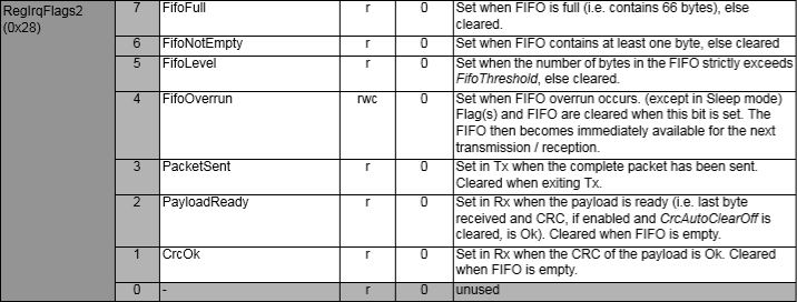
The RegIrqFlags2 CrcOk (bit 1) was set and the message was corrupt.
RegIrqFlags2 bit flags from SX1231 datasheet
I have added code to check the CRC on inbound messages if this functionality is enabled. So the library can be used with CRCs disabled I have added a flag to the OnDataReceivedEventArgs class to indicate whether the CRC on the inbound message was OK.
private readonly Object Rfm9XRegFifoLock = new object();
...
private void ProcessPayloadReady(RegIrqFlags1 irqFlags1, RegIrqFlags2 irqFlags2)
{
	byte? address = null;
	byte numberOfBytes;
	byte[] messageBytes;

	lock (Rfm9XRegFifoLock)
	{
		// Read the length of the buffer if variable length packets
		if (PacketFormat == RegPacketConfig1PacketFormat.VariableLength)
		{
			numberOfBytes = RegisterManager.ReadByte((byte)Rfm69HcwDevice.Registers.RegFifo);
		}
		else
		{
			numberOfBytes = PayloadLength;
		}

		// Remove the address from start of the payload
		if (AddressingEnabled)
		{
			address = RegisterManager.ReadByte((byte)Rfm69HcwDevice.Registers.RegFifo);

			Debug.WriteLine("{0:HH:mm:ss.fff} Address 0X{1:X2} {2}", DateTime.Now, address, Convert.ToString((byte)address, 2).PadLeft(8, '0'));
			numberOfBytes--;
		}

		// Allocate a buffer for the payload and read characters from the Fifo
		messageBytes = new byte[numberOfBytes];

		for (int i = 0; i < numberOfBytes; i++)
		{
			messageBytes[i] = RegisterManager.ReadByte((byte)Rfm69HcwDevice.Registers.RegFifo);
		}
	}
...
public void SendMessage(byte[] messageBytes)
{
#region Guard conditions
#endregion

	lock (Rfm9XRegFifoLock)
	{
		SetMode(RegOpModeMode.StandBy);

		if (PacketFormat == RegPacketConfig1PacketFormat.VariableLength)
		{
			RegisterManager.WriteByte((byte)Registers.RegFifo, (byte)messageBytes.Length);
		}

		foreach (byte b in messageBytes)
		{
			this.RegisterManager.WriteByte((byte)Registers.RegFifo, b);
		}

		SetMode(RegOpModeMode.Transmit);
	}
}
I can most probably reduce the duration which I hold the lock for but that will require some more stress testing.
While doing some stress testing I noticed an odd message go past in the Visual Studio output window. I had multiple devices sending addressed messages (both individual and broadcast) to the Adafruit RFM69 HCW Radio Bonnet, on my Windows 10 IoT Core device while it was sending a message every 5 seconds.
Received From 153 a 13 byte message Hello World:7
18:43:56.544 RegIrqFlags2 01100110
18:43:56.558 RegIrqFlags1 11011001
18:43:56.575 Address 0X66 01100110
Received From 102 a 15 byte message Hello World:162
The thread 0x254 has exited with code 0 (0x0).
18:43:57.699 Send-hello world 6:43:57 PM
18:43:57.699 RegIrqFlags2 01100110
18:43:57.731 RegIrqFlags1 10000000
18:43:57.747 Address 0X66 01100110
18:43:57.765 Send-Done
Received From 102 a 15 byte message Hello Woooooooo
18:43:57.987 RegIrqFlags2 00001000
18:43:58.003 RegIrqFlags1 10110000
18:43:58.017 Transmit-Done
Transmit-Done
18:43:58.825 RegIrqFlags2 01100110
18:43:58.838 RegIrqFlags1 11011001
18:43:58.857 Address 0X66 01100110
Received From 102 a 15 byte message Hello World:164
18:43:59.966 RegIrqFlags2 01100110
18:43:59.979 RegIrqFlags1 11011001
18:43:59.998 Address 0X66 01100110
The odd thing was that the RegIrqFlags2 CrcOk (bit 1) was set but the message was still corrupt.
RegIrqFlags2 bit flags from SX1231 datasheet
After looking at the code I think the problem was the reading of the received message bytes from the device FIFO and the writing of bytes of message to be transmitted into the device FIFO overlapped. To stop this occurring again I have added code to synchronise access (using a Lock) to the FIFO.
private readonly Object Rfm9XRegFifoLock = new object();
...
private void ProcessPayloadReady(RegIrqFlags1 irqFlags1, RegIrqFlags2 irqFlags2)
{
	byte? address = null;
	byte numberOfBytes;
	byte[] messageBytes;

	lock (Rfm9XRegFifoLock)
	{
		// Read the length of the buffer if variable length packets
		if (PacketFormat == RegPacketConfig1PacketFormat.VariableLength)
		{
			numberOfBytes = RegisterManager.ReadByte((byte)Rfm69HcwDevice.Registers.RegFifo);
		}
		else
		{
			numberOfBytes = PayloadLength;
		}

		// Remove the address from start of the payload
		if (AddressingEnabled)
		{
			address = RegisterManager.ReadByte((byte)Rfm69HcwDevice.Registers.RegFifo);

			Debug.WriteLine("{0:HH:mm:ss.fff} Address 0X{1:X2} {2}", DateTime.Now, address, Convert.ToString((byte)address, 2).PadLeft(8, '0'));
			numberOfBytes--;
		}

		// Allocate a buffer for the payload and read characters from the Fifo
		messageBytes = new byte[numberOfBytes];

		for (int i = 0; i < numberOfBytes; i++)
		{
			messageBytes[i] = RegisterManager.ReadByte((byte)Rfm69HcwDevice.Registers.RegFifo);
		}
	}
...
public void SendMessage(byte[] messageBytes)
{
#region Guard conditions
#endregion

	lock (Rfm9XRegFifoLock)
	{
		SetMode(RegOpModeMode.StandBy);

		if (PacketFormat == RegPacketConfig1PacketFormat.VariableLength)
		{
			RegisterManager.WriteByte((byte)Registers.RegFifo, (byte)messageBytes.Length);
		}

		foreach (byte b in messageBytes)
		{
			this.RegisterManager.WriteByte((byte)Registers.RegFifo, b);
		}

		SetMode(RegOpModeMode.Transmit);
	}
}
The code has been running for a day without any corrupted messages so the lock appears to be working. I can most probably reduce the duration which I hold the lock for but that will require some more stress testing.
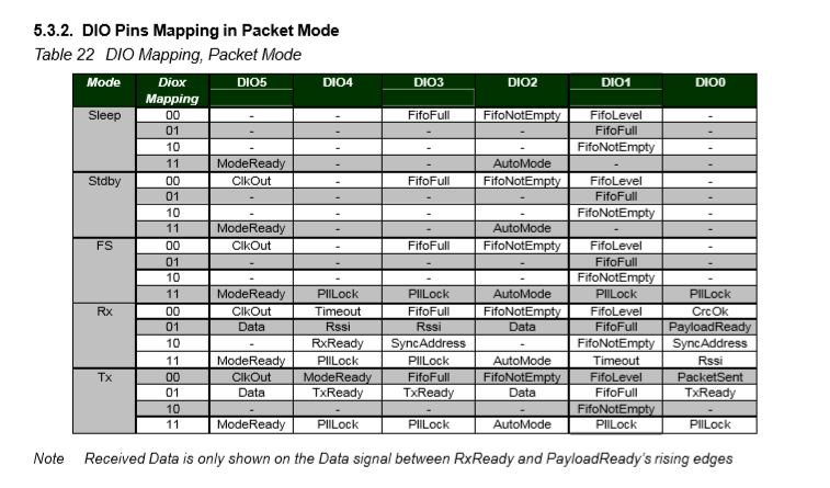
The RFM69CW/RFM69HCW module (based on the Semtech SX1231/SX1231H) has configurable digital outputs (RegDIOMapping1 & RegDIOMapping2) . Which I use to trigger interrupts on my Windows 10 IoT Core or Arduino devices. Currently (Sep 2019) the library only supports the mapping of the digital outputs D0 & D1 when the RFM69 is in Packet Mode.
RegiDIOMapping0 & RegDIOMapping2 settings for DIO thru DIO5
I added some additional constants and enumerations for the other settings configured in RegDioMapping1 & RegDioMapping2.
I had several failed attempts at defining suitable enumerations for configuring the RegDioMapping1 & RegDioMapping2 registers. I initially started with an enumeration for each Mode (Sleep, StandBy etc.) but the implementation was quite complex. The initial version only supports DIO0 & DIO1 as most of the shields I have, only DIO0 adn/or DIO1 are connected.
Enums and Masks – Packet lengths, addressing & CRCs
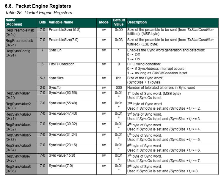
The RFM69CW/RFM69HCW module (based on the Semtech SX1231/SX1231H) has configurable (RegSyncConfig) synchronisation sequences (the length, tolerance for errors and the individual byte values).
By default synchronisation is enabled and a default sequence of bytes is used, in my library synchronisation is NOT enabled until a SyncValue is provided.
I added some additional constants and enumerations for the other settings configured in RegSyncConfig.
// RegSyncConfig
// This is private because default ignored and flag set based on SyncValues parameter being specified rather than default
private enum RegSyncConfigSyncOn
{
	Off = 0b00000000,
	On = 0b10000000
}

public enum RegSyncConfigFifoFileCondition
{
	SyncAddressInterrupt = 0b00000000,
	FifoFillCondition =    0b01000000
}

private const RegSyncConfigFifoFileCondition SyncFifoFileConditionDefault = RegSyncConfigFifoFileCondition.SyncAddressInterrupt;
readonly byte[] SyncValuesDefault = {0x01, 0x01, 0x01, 0x01};
public const byte SyncValuesSizeDefault = 4;
public const byte SyncValuesSizeMinimum = 1;
public const byte SyncValuesSizeMaximum = 8;

private const byte SyncToleranceDefault = 0;
public const byte SyncToleranceMinimum = 0;
public const byte SyncToleranceMaximum = 7;
I also added some guard conditions to the initialise method which validate the syncFifoFileCondition, syncTolerance and syncValues length.
public void Initialise(RegOpModeMode modeAfterInitialise,
	BitRate bitRate = BitRateDefault,
	ushort frequencyDeviation = frequencyDeviationDefault,
	double frequency = FrequencyDefault,
	ListenModeIdleResolution listenModeIdleResolution = ListenModeIdleResolutionDefault, ListenModeRXTime listenModeRXTime = ListenModeRXTimeDefault, ListenModeCrieria listenModeCrieria = ListenModeCrieriaDefault, ListenModeEnd listenModeEnd = ListenModeEndDefault,
	byte listenCoefficientIdle = ListenCoefficientIdleDefault,
	byte listenCoefficientReceive = ListenCoefficientReceiveDefault,
	bool pa0On = pa0OnDefault, bool pa1On = pa1OnDefaut, bool pa2On = pa2OnDefault, byte outputpower = OutputpowerDefault,
	PaRamp paRamp = PaRampDefault,
	bool ocpOn = OcpOnDefault, byte ocpTrim = OcpTrimDefault,
	LnaZin lnaZin = LnaZinDefault, LnaCurrentGain lnaCurrentGain = LnaCurrentGainDefault, LnaGainSelect lnaGainSelect = LnaGainSelectDefault,
	byte dccFrequency = DccFrequencyDefault, RxBwMant rxBwMant = RxBwMantDefault, byte RxBwExp = RxBwExpDefault,
	byte dccFreqAfc = DccFreqAfcDefault, byte rxBwMantAfc = RxBwMantAfcDefault, byte bxBwExpAfc = RxBwExpAfcDefault,
	ushort preambleSize = PreambleSizeDefault,
	RegSyncConfigFifoFileCondition? syncFifoFileCondition = null, byte? syncTolerance = null, byte[] syncValues = null,
	RegPacketConfig1PacketFormat packetFormat = RegPacketConfig1PacketFormat.FixedLength,
	RegPacketConfig1DcFree packetDcFree = RegPacketConfig1DcFreeDefault,
	bool packetCrc = PacketCrcOnDefault,
	bool packetCrcAutoClearOff = PacketCrcAutoClearOffDefault,
	RegPacketConfig1CrcAddressFiltering packetAddressFiltering = PacketAddressFilteringDefault,
	byte payloadLength = PayloadLengthDefault,
	byte addressNode = NodeAddressDefault, byte addressbroadcast = BroadcastAddressDefault,
	TxStartCondition txStartCondition = TxStartConditionDefault, byte fifoThreshold = FifoThresholdDefault,
	byte interPacketRxDelay = InterPacketRxDelayDefault, bool restartRx = RestartRxDefault, bool autoRestartRx = AutoRestartRxDefault,
	byte[] aesKey = null
	)
{
	RegOpModeModeCurrent = modeAfterInitialise;
	PacketFormat = packetFormat;

	#region RegSyncConfig + RegSyncValue1 to RegSyncValue8 guard conditions
	if (syncValues != null)
	{
		// If sync enabled (i.e. SyncValues array provided) check that SyncValues not to short/long and SyncTolerance not to small/big
		if ((syncValues.Length < SyncValuesSizeMinimum) || (syncValues.Length > SyncValuesSizeMaximum))
		{
			throw new ArgumentException($"The syncValues array length must be between {SyncValuesSizeMinimum} and {SyncValuesSizeMaximum} bytes", "syncValues");
		}
		if (syncTolerance.HasValue)
		{
			if ((syncTolerance < SyncToleranceMinimum) || (syncTolerance > SyncToleranceMaximum))
			{
				throw new ArgumentException($"The syncTolerance size must be between {SyncToleranceMinimum} and {SyncToleranceMaximum}", "syncTolerance");
			}
		}
	}
	else
	{
		// If sync not enabled (i.e. SyncValues array null) check that no syncFifoFileCondition or syncTolerance configuration specified
		if (syncFifoFileCondition.HasValue)
		{
			throw new ArgumentException($"If Sync not enabled syncFifoFileCondition is not supported", "syncFifoFileCondition");
		}

		if (syncTolerance.HasValue)
		{
			throw new ArgumentException($"If Sync not enabled SyncTolerance is not supported", "syncTolerance");
		}
	}
	#endregion
I also ensure that the syncFifoFileCondition and syncTolerance are not specified if synchronisation is not enabled.
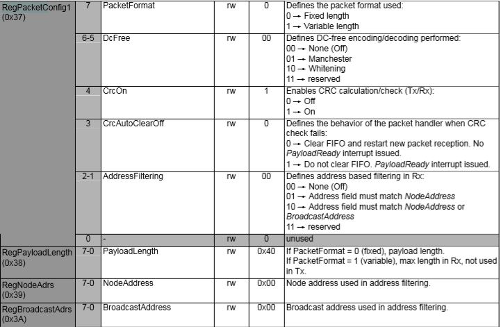
The library also supports the built in RFRM69 node and broadcast addressing which is enabled when the AddressNode and/or AddressBroadcast parameters of the Initialise method are set.
RegPacketConfig1 address filtering options
My first attempt at getting encryption and addressing working together failed badly, the Windows 10 IoT Core device didn’t receive any addressed messages when encryption was enabled. So, I went back and re-read the datasheet again and noticed
“If the address filtering is expected then AddressFiltering must be enabled on the transmitter side as well to prevent address byte to be encrypted”(Sic).
The Arduino client code had to be modified so I could set the node + broadcast address registers and AddressFiltering bit flag in RegPacketConfig1
My RMRFM69.h modifications
enum moduleType {RFM65, RFM65C, RFM69, RFM69C, RFM69H, RFM69HC};

 #define ADDRESS_NODE_DEFAULT 0x0
 #define ADDRESS_BROADCAST_DEFAULT 0x0
 #define ADDRESSING_ENABLED_NODE 0x2
 #define ADDRESSING_ENABLED_NODE_AND_BROADCAST 0x4

	class RMRFM69
	{
	 public:
		 RMRFM69(SPIClass &spiPort, byte csPin, byte dio0Pin, byte rstPin);
		 modulationType Modulation; //OOK/FSK/GFSK
		 moduleType COB;				//Chip on board
		 uint32_t Frequency;			//unit: KHz
		 uint32_t SymbolTime;			//unit: ns
		 uint32_t Devation;				//unit: KHz
		 word BandWidth;				//unit: KHz
		 byte OutputPower;				//unit: dBm   range: 0-31 [-18dBm~+13dBm] for RFM69/RFM69C
										//            range: 0-31 [-11dBm~+20dBm] for RFM69H/RFM69HC
		 word PreambleLength;			//unit: byte

		 bool CrcDisable; //fasle: CRC enable�� & use CCITT 16bit
						  //true : CRC disable
		 bool CrcMode;	//false: CCITT

		 bool FixedPktLength; //false: for contain packet length in Tx message, the same mean with variable lenth
							  //true : for doesn't include packet length in Tx message, the same mean with fixed length
		 bool AesOn;		  //false:
							  //true:
		 bool AfcOn;		  //false:
							  //true:
		 byte SyncLength;	 //unit: none, range: 1-8[Byte], value '0' is not allowed!
		 byte SyncWord[8];
		 byte PayloadLength; //PayloadLength is need to be set a value, when FixedPktLength is true.
		 byte AesKey[16];	//AES Key block, note [0]->[15] == MSB->LSB
		 byte AddressNode = ADDRESS_NODE_DEFAULT;
		 byte AddressBroadcast = ADDRESS_BROADCAST_DEFAULT;

		 void vInitialize(void);
		 void vConfig(void);
		 void vGoRx(void);
		 void vGoStandby(void);
		 void vGoSleep(void);
		 bool bSendMessage(byte msg[], byte length);
		 bool bSendMessage(byte Address, byte msg[], byte length);
		 byte bGetMessage(byte msg[]);
		 void vRF69SetAesKey(void);
		 void vTrigAfc(void);

		 void vDirectRx(void);			  //go continuous rx mode, with init. inside
		 void vChangeFreq(uint32_t freq); //change frequency
		 byte bReadRssi(void);			  //read rssi value
		 void dumpRegisters(Stream& out);
My RMRFM69.cpp modifications in vConfig
 if(!CrcDisable)
 	{
 	i += CrcOn;
	if(CrcMode)
		i += CrcCalc_IBM;
	else
		i += CrcCalc_CCITT;
	}

if((AddressNode!=ADDRESS_NODE_DEFAULT) || (AddressBroadcast==ADDRESS_BROADCAST_DEFAULT))
   {
      i += ADDRESSING_ENABLED_NODE;
   }

if((AddressNode!=ADDRESS_NODE_DEFAULT) || (AddressBroadcast!=ADDRESS_BROADCAST_DEFAULT))
  {
     i += ADDRESSING_ENABLED_NODE_AND_BROADCAST;
  }

 vSpiWrite(((word)RegPacketConfig1<<8)+i);
I also validate the lengths of the messages to be sent taking into account whether encryption is enabled\disabled.
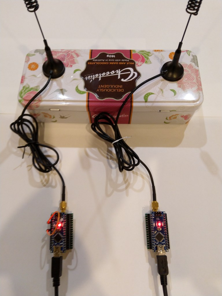
Every so often my Enums & Masks test harness locked up and stopped receiving messages from my test rig. This seemed to happen more often when the send functionality of my library was not being used.
easysensors RFM69HCW test rig
After 5 to 30 minutes (a couple of times it was 5 to 8 hours overnight) the application stopped receiving messages and wouldn’t resume until the application (device reset) was restarted or the RegOpmode-Mode was quickly changed to sleep then back to receive.
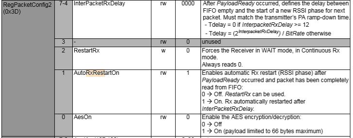
I had noticed this code in the Low Power Lab and wondered what it was for. The HopeRF library didn’t appear to have code like this to restart reception which was interesting.
void RFM69::send(uint16_t toAddress, const void* buffer, uint8_t bufferSize, bool requestACK)
{
  writeReg(REG_PACKETCONFIG2, (readReg(REG_PACKETCONFIG2) & 0xFB) | RF_PACKET2_RXRESTART); // avoid RX deadlocks
  uint32_t now = millis();
  while (!canSend() && millis() - now < RF69_CSMA_LIMIT_MS) receiveDone();
  sendFrame(toAddress, buffer, bufferSize, requestACK, false);
}

// should be called immediately after reception in case sender wants ACK
void RFM69::sendACK(const void* buffer, uint8_t bufferSize) {
  ACK_REQUESTED = 0;   // TWS added to make sure we don't end up in a timing race and infinite loop sending Acks
  uint16_t sender = SENDERID;
  int16_t _RSSI = RSSI; // save payload received RSSI value
  writeReg(REG_PACKETCONFIG2, (readReg(REG_PACKETCONFIG2) & 0xFB) | RF_PACKET2_RXRESTART); // avoid RX deadlocks
  uint32_t now = millis();
  while (!canSend() && millis() - now < RF69_CSMA_LIMIT_MS) receiveDone();
  SENDERID = sender;    // TWS: Restore SenderID after it gets wiped out by receiveDone()
  sendFrame(sender, buffer, bufferSize, false, true);
  RSSI = _RSSI; // restore payload RSSI
}

void RFM69::receiveBegin() {
  DATALEN = 0;
  SENDERID = 0;
  TARGETID = 0;
  PAYLOADLEN = 0;
  ACK_REQUESTED = 0;
  ACK_RECEIVED = 0;
#if defined(RF69_LISTENMODE_ENABLE)
  RF69_LISTEN_BURST_REMAINING_MS = 0;
#endif
  RSSI = 0;
  if (readReg(REG_IRQFLAGS2) & RF_IRQFLAGS2_PAYLOADREADY)
    writeReg(REG_PACKETCONFIG2, (readReg(REG_PACKETCONFIG2) & 0xFB) | RF_PACKET2_RXRESTART); // avoid RX deadlocks
  writeReg(REG_DIOMAPPING1, RF_DIOMAPPING1_DIO0_01); // set DIO0 to "PAYLOADREADY" in receive mode
  setMode(RF69_MODE_RX);
}
In the debug output you can see that clock frequencies of the two test devices are slightly different. Every so often they transmit close enough to corrupt one of the message payloads which causes the deadlock.
Sometimes while testing code you notice something odd. Every so often the Enums & Masks application locks up and stops receiving messages from my test rig.
easysensors RFM69HCW test rig
The symptom is that after 5 to 30 minutes the application stops receiving messages
21:37:37.568 RegIrqFlags1 11011001
21:37:37.583 Address 0X99 10011001
21:37:37 Received 14 byte message Hello World:61
..21:37:38.693 RegIrqFlags2 01100110
21:37:38.706 RegIrqFlags1 11011001
21:37:38.724 Address 0X99 10011001
21:37:38 Received 14 byte message Hello World:62
............The thread 0xba8 has exited with code 0 (0x0).
.................................................................................................................................................The thread 0xf90 has exited with code 0 (0x0).
.....................The thread 0xe30 has exited with code 0 (0x0).
.......................The thread 0xa04 has exited with code 0 (0x0).
................................The thread 0xc8c has exited with code 0 (0x0).
..........................................................................................The thread 0xc38 has exited with code 0 (0x0).
......................The thread 0xf68 has exited with code 0 (0x0).
......................................................................................The thread 0x1c8 has exited with code 0 (0x0).
..........The thread 0xeb8 has exited with code 0 (0x0).
..............................................................The thread 0xbb8 has exited with code 0 (0x0).
..........The thread 0xdc0 has exited with code 0 (0x0).
...............................The thread 0x820 has exited with code 0 (0x0).
....................................The thread 0xaac has exited with code 0 (0x0).
......The thread 0xbf0 has exited with code 0 (0x0).
............................................The thread 0x4e8 has exited with code 0 (0x0).
...............................The thread 0x1b4 has exited with code 0 (0x0).
...............................................................The thread 0xbdc has exited with code 0 (0x0).
....................The thread 0xb60 has exited with code 0 (0x0).
.........................................................................................................The thread 0x510 has exited with code 0 (0x0).
........The thread 0xf60 has exited with code 0 (0x0).
........................................................The thread 0x3c0 has exited with code 0 (0x0).
......................................The thread 0xa4c has exited with code 0 (0x0).
..................................................................The thread 0x9e0 has exited with code 0 (0x0).
....................The thread 0xd74 has exited with code 0 (0x0).
............................The thread 0xfa0 has exited with code 0 (0x0).
..................................................................................................The thread 0xfe0 has exited with code 0 (0x0).
....................................................................................The thread 0xdd4 has exited with code 0 (0x0).
........................The thread 0xc00 has exited with code 0 (0x0).
..................................The thread 0x478 has exited with code 0 (0x0).
.........................The thread 0x88c has exited with code 0 (0x0).
...........................................The thread 0x280 has exited with code 0 (0x0).
..........................................The thread 0x8e4 has exited with code 0 (0x0).
............The thread 0x410 has exited with code 0 (0x0).
..............................................The thread 0xa70 has exited with code 0 (0x0).
................The thread 0x994 has exited with code 0 (0x0).
....................The thread 0x298 has exited with code 0 (0x0).
..............The thread 0x3a4 has exited with code 0 (0x0).
............................................................The thread 0xa2c has exited with code 0 (0x0).
..........The thread 0x208 has exited with code 0 (0x0).
..........................................................................The thread 0xbd4 has exited with code 0 (0x0).
............The thread 0xfdc has exited with code 0 (0x0).
........................................................................The thread 0x36c has exited with code 0 (0x0).
...........22:08:57.638 RegIrqFlags2 01100110
22:08:57.658 RegIrqFlags1 11011001
22:08:57.676 Address 0X66 01100110
22:08:57 Received 15 byte message Hello World:157
22:08:57.807 RegIrqFlags2 01100110
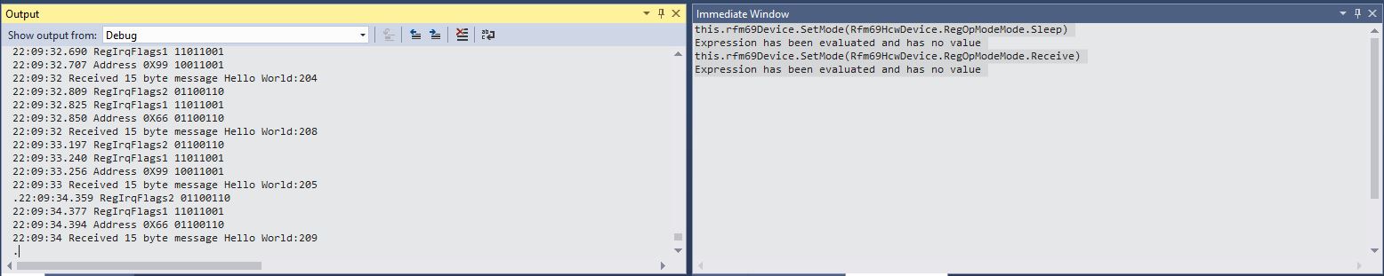
But, every so often it would after many minutes start up again without me doing anything (I noticed this after leaving application running overnight). I could get the application to restart by putting a break point on the Debug.Write(“.”) and toggling the OperationMode from Sleep to Receive
Using Visual Studio Immediate Windows to execute SetMode
I have found if the device is transmitting every so often the lockups are also much less likely. To help with debugging the issue I have wired up the three buttons on the Adafruit Radio Bonnet to call different diagnostic code
Looks like this maybe a bit of a heisenbug as it takes a longish time to appear and poking around in the debugger and adding more diagnostics changes the frequency the error.
Received 16 byte message
Receive-Done
.............................Receive-No wait
Received 16 byte message
Receive-Done
Receive-No wait
Received 16 byte message
Receive-Done
....Receive-No wait
Received 16 byte message
Receive-Done
Receive-No wait
Received 16 byte message
Receive-Done
.............
Pressing button one restarts inbound messages for a while, button two sits in an endless loop, button three reads in a 16 byte message of 0x10 characters, which I think is buffer length. I have added code to catch exceptions and stop re-entrancy but it never seems to get triggered.
The RFM69CW/RFM69HCW module (based on the Semtech SX1231/SX1231H) has configurable (RegSyncConfig) synchronisation sequences (the length, tolerance for errors and the individual byte values).
By default synchronisation is enabled and a default sequence of bytes is used, in my library synchronisation is NOT enabled until a SyncValue is provided.
I added some additional constants and enumerations for the other settings configured in RegSyncConfig.
// RegSyncConfig
// This is private because default ignored and flag set based on SyncValues parameter being specified rather than default
private enum RegSyncConfigSyncOn
{
	Off = 0b00000000,
	On = 0b10000000
}

public enum RegSyncConfigFifoFileCondition
{
	SyncAddressInterrupt = 0b00000000,
	FifoFillCondition =    0b01000000
}

private const RegSyncConfigFifoFileCondition SyncFifoFileConditionDefault = RegSyncConfigFifoFileCondition.SyncAddressInterrupt;
readonly byte[] SyncValuesDefault = {0x01, 0x01, 0x01, 0x01};
public const byte SyncValuesSizeDefault = 4;
public const byte SyncValuesSizeMinimum = 1;
public const byte SyncValuesSizeMaximum = 8;

private const byte SyncToleranceDefault = 0;
public const byte SyncToleranceMinimum = 0;
public const byte SyncToleranceMaximum = 7;
I also added some guard conditions to the initialise method which validate the syncFifoFileCondition, syncTolerance and syncValues length.
public void Initialise(RegOpModeMode modeAfterInitialise,
	BitRate bitRate = BitRateDefault,
	ushort frequencyDeviation = frequencyDeviationDefault,
	double frequency = FrequencyDefault,
	ListenModeIdleResolution listenModeIdleResolution = ListenModeIdleResolutionDefault, ListenModeRXTime listenModeRXTime = ListenModeRXTimeDefault, ListenModeCrieria listenModeCrieria = ListenModeCrieriaDefault, ListenModeEnd listenModeEnd = ListenModeEndDefault,
	byte listenCoefficientIdle = ListenCoefficientIdleDefault,
	byte listenCoefficientReceive = ListenCoefficientReceiveDefault,
	bool pa0On = pa0OnDefault, bool pa1On = pa1OnDefaut, bool pa2On = pa2OnDefault, byte outputpower = OutputpowerDefault,
	PaRamp paRamp = PaRampDefault,
	bool ocpOn = OcpOnDefault, byte ocpTrim = OcpTrimDefault,
	LnaZin lnaZin = LnaZinDefault, LnaCurrentGain lnaCurrentGain = LnaCurrentGainDefault, LnaGainSelect lnaGainSelect = LnaGainSelectDefault,
	byte dccFrequency = DccFrequencyDefault, RxBwMant rxBwMant = RxBwMantDefault, byte RxBwExp = RxBwExpDefault,
	byte dccFreqAfc = DccFreqAfcDefault, byte rxBwMantAfc = RxBwMantAfcDefault, byte bxBwExpAfc = RxBwExpAfcDefault,
	ushort preambleSize = PreambleSizeDefault,
	RegSyncConfigFifoFileCondition? syncFifoFileCondition = null, byte? syncTolerance = null, byte[] syncValues = null,
	RegPacketConfig1PacketFormat packetFormat = RegPacketConfig1PacketFormat.FixedLength,
	RegPacketConfig1DcFree packetDcFree = RegPacketConfig1DcFreeDefault,
	bool packetCrc = PacketCrcOnDefault,
	bool packetCrcAutoClearOff = PacketCrcAutoClearOffDefault,
	RegPacketConfig1CrcAddressFiltering packetAddressFiltering = PacketAddressFilteringDefault,
	byte payloadLength = PayloadLengthDefault,
	byte addressNode = NodeAddressDefault, byte addressbroadcast = BroadcastAddressDefault,
	TxStartCondition txStartCondition = TxStartConditionDefault, byte fifoThreshold = FifoThresholdDefault,
	byte interPacketRxDelay = InterPacketRxDelayDefault, bool restartRx = RestartRxDefault, bool autoRestartRx = AutoRestartRxDefault,
	byte[] aesKey = null
	)
{
	RegOpModeModeCurrent = modeAfterInitialise;
	PacketFormat = packetFormat;

	#region RegSyncConfig + RegSyncValue1 to RegSyncValue8 guard conditions
	if (syncValues != null)
	{
		// If sync enabled (i.e. SyncValues array provided) check that SyncValues not to short/long and SyncTolerance not to small/big
		if ((syncValues.Length < SyncValuesSizeMinimum) || (syncValues.Length > SyncValuesSizeMaximum))
		{
			throw new ArgumentException($"The syncValues array length must be between {SyncValuesSizeMinimum} and {SyncValuesSizeMaximum} bytes", "syncValues");
		}
		if (syncTolerance.HasValue)
		{
			if ((syncTolerance < SyncToleranceMinimum) || (syncTolerance > SyncToleranceMaximum))
			{
				throw new ArgumentException($"The syncTolerance size must be between {SyncToleranceMinimum} and {SyncToleranceMaximum}", "syncTolerance");
			}
		}
	}
	else
	{
		// If sync not enabled (i.e. SyncValues array null) check that no syncFifoFileCondition or syncTolerance configuration specified
		if (syncFifoFileCondition.HasValue)
		{
			throw new ArgumentException($"If Sync not enabled syncFifoFileCondition is not supported", "syncFifoFileCondition");
		}

		if (syncTolerance.HasValue)
		{
			throw new ArgumentException($"If Sync not enabled SyncTolerance is not supported", "syncTolerance");
		}
	}
	#endregion
I also ensure that the syncFifoFileCondition and syncTolerance are not specified if synchronisation is not enabled.
The Arduino client code works though I need modify it so I can do more testing of the initialise method parameter options.