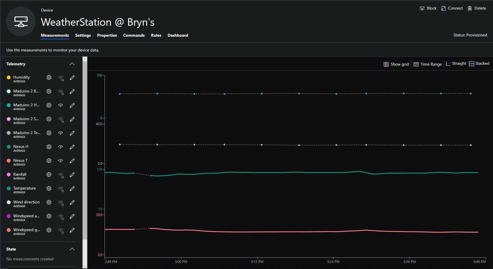
Over the weekend I have been testing a beta Ingenuity Micro Nexus device building a series of simple applications to exercise all of the input and output ports.
The device is equipped with 11 x Seeedstudio Grove compatible sockets (2 x UART, 5 x I2C, 3 x ADC, 1 x PWM sockets) which support a wide variety of sensors.

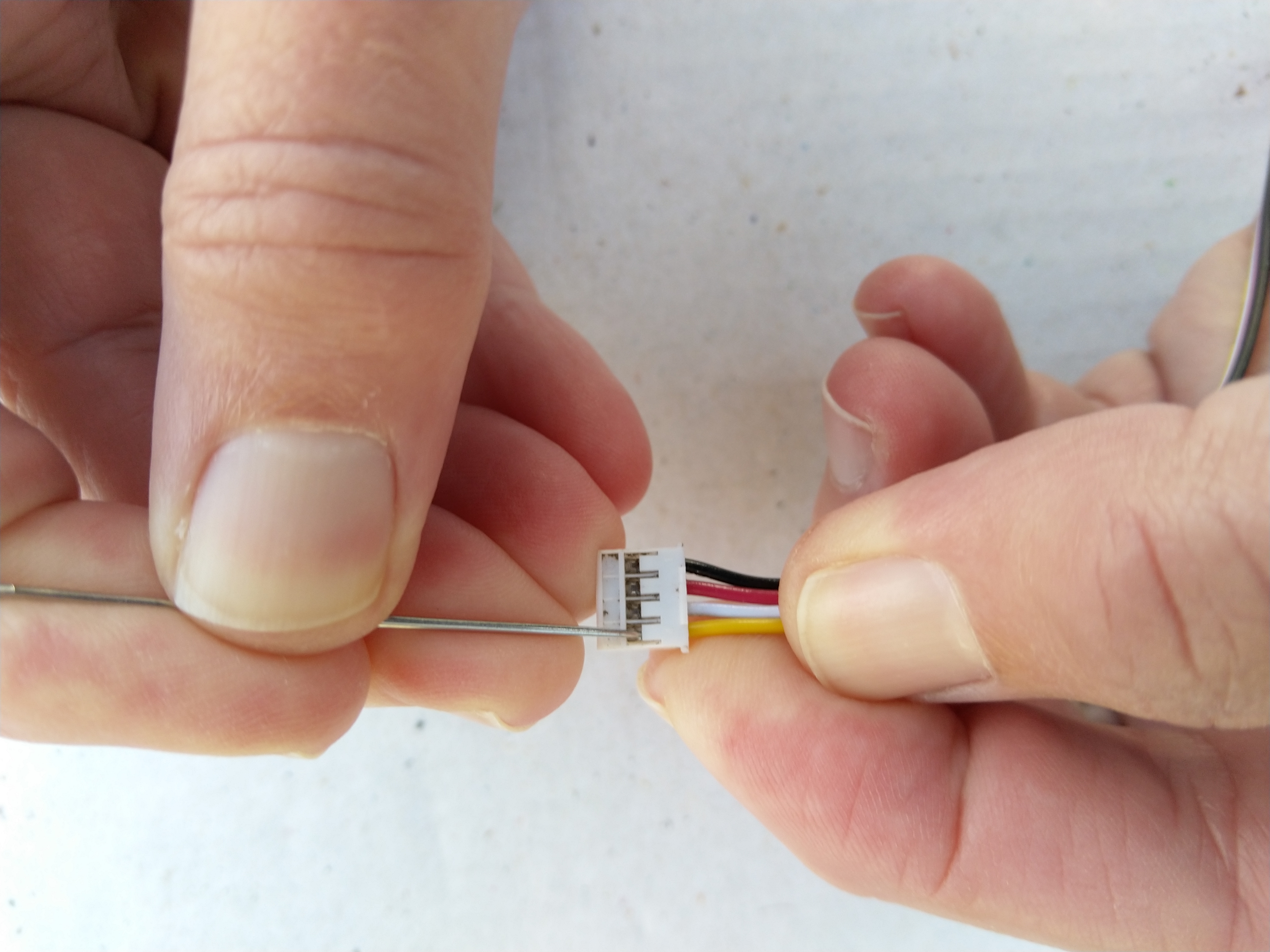
So I could test all the analog port pins I modified a Grove Branch Cable by carefully unplugging the yellow and white branch cables and replacing them with yellow and white (plugged into the yellow connector on both sensor connectors) cables split from a spare Grove Universal Buckled 20cm cable. I used a pair of Grove Rotary Angle Sensors as analog inputs.
public static void Main()
{
	AnalogInput analogSensor1 = new AnalogInput
	(
		Pins.Analog.Socket1Pin1
		//Pins.Analog.Socket2Pin1
		//Pins.Analog.Socket3Pin1
		//Pins.Analog.Socket4Pin1
	);
	AnalogInput analogSensor2 = new AnalogInput
	(
		Pins.Analog.Socket1Pin2
		//Pins.Analog.Socket2Pin2
		//Pins.Analog.Socket3Pin2
		//Pins.Analog.Socket4Pin2
	);

	Debug.Print("Program running");

	while (true)
	{
		double sensorValue1 = analogSensor1.Read();
		double sensorValue2 = analogSensor2.Read();

		Debug.Print("Value 1:" + sensorValue1.ToString("F2") + " Value 2:" + sensorValue2.ToString("F2"));

		Thread.Sleep(500);
	}
}
To speed up testing of the GPIO and PWM ports I modified a Grove Universal Buckled 20cm cable by twisting the white and yellow wires.
I used a pair of Grove illuminated buttons (Red, Yellow or Blue). The button was the digital input, the LED was the digital output. By uncommenting pairs of socket pins I could quickly step through all the ports checking that pressing the button toggled the state of the LED.
public class Program
{
	const Cpu.Pin ButtonLedPin =
		Pins.Gpio.Socket1Pin1;
		//Pins.Gpio.Socket1Pin2;
		//Pins.Gpio.Socket2Pin1;
		//Pins.Gpio.Socket2Pin2;
		//Pins.Gpio.Socket3Pin1;
		//Pins.Gpio.Socket3Pin2;
		//Pins.Gpio.Socket4Pin1;
		//Pins.Gpio.Socket4Pin2;
		//Pins.Gpio.Socket5Pin1;
		//Pins.Gpio.Socket5Pin2;
		//Pins.Gpio.Socket6Pin1;
		//Pins.Gpio.Socket6Pin2;
		//Pins.Gpio.Socket7Pin1;
		//Pins.Gpio.Socket7Pin2;
		//Pins.Gpio.Socket8Pin1;
		//Pins.Gpio.Socket8Pin2;
		//Pins.Gpio.Socket9Pin1;
		//Pins.Gpio.Socket9Pin2;
		//Pins.Gpio.Socket10Pin1;
		//Pins.Gpio.Socket10Pin2;
		//Pins.Gpio.Socket11Pin1;
		//Pins.Gpio.Socket11Pin2;
	const Cpu.Pin ButtonPin =
		//Pins.Gpio.Socket1Pin1;
		Pins.Gpio.Socket1Pin2;
		//Pins.Gpio.Socket2Pin1;
		//Pins.Gpio.Socket2Pin2;
		//Pins.Gpio.Socket3Pin1;
		//Pins.Gpio.Socket3Pin2;
		//Pins.Gpio.Socket4Pin1;
		//Pins.Gpio.Socket4Pin2;
		//Pins.Gpio.Socket5Pin1;
		//Pins.Gpio.Socket5Pin2;
		//Pins.Gpio.Socket6Pin1;
		//Pins.Gpio.Socket6Pin2;
		//Pins.Gpio.Socket7Pin1;
		//Pins.Gpio.Socket7Pin2;
		//Pins.Gpio.Socket8Pin1;
		//Pins.Gpio.Socket8Pin2;
		//Pins.Gpio.Socket9Pin1;
		//Pins.Gpio.Socket9Pin2;
		//Pins.Gpio.Socket10Pin1;
		//Pins.Gpio.Socket10Pin2;
		//Pins.Gpio.Socket11Pin1;
		//Pins.Gpio.Socket11Pin2;
	static OutputPort buttonLed = new OutputPort(ButtonLedPin, false);

	public static void Main()
	{
		InterruptPort button = new InterruptPort(ButtonPin, false, Port.ResistorMode.Disabled, Port.InterruptMode.InterruptEdgeBoth);
		button.OnInterrupt += Button_OnInterrupt;

		Debug.Print("Program running");

		Thread.Sleep(Timeout.Infinite);
	}

	private static void Button_OnInterrupt(uint data1, uint data2, DateTime time)
	{
		Debug.Print(time.ToString("hh:mm:ss") + " Data1:" + data1 + " Data 2:" + data2);

		buttonLed.Write(!buttonLed.Read());
	}
So I could test the PWM port I used a Grove Rotary Angle Sensor plugged into Socket 4 and a Grove LED (Red, Green or Blue) plugged into Socket 6 with a standard cable for pin 1 or my twisted cable for pin 2.
public class Program
{
	public static void Main()
	{
		AnalogInput analogSensor = new AnalogInput(Pins.Analog.Socket4Pin1);

		//const Cpu.PWMChannel LedPin = Pins.Pwm.Socket6Pin1;
		const Cpu.PWMChannel LedPin = Pins.Pwm.Socket6Pin2;

		PWM ledDim = new PWM(LedPin, 1000.0, 0.0, false);

		ledDim.Start();
		Debug.Print("Program running");

		while (true)
		{
			double sensorValue = analogSensor.Read();

			Debug.Print(DateTime.Now.ToString("hh:mm:ss") +" Value:" + sensorValue.ToString("F1"));

			ledDim.DutyCycle = sensorValue;

			Thread.Sleep(500);
		}
	}
}
All of the Analog, GPIO & PWM sockets/pins worked as expected, there maybe a couple of extra PWM outputs available on I2C sockets.