Random wanderings through Microsoft Azure esp. PaaS plumbing, the IoT bits, AI on Micro controllers, AI on Edge Devices, .NET nanoFramework, .NET Core on *nix and ML.NET+ONNX
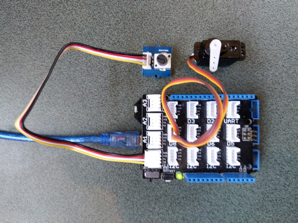
The next step was to figure out how to configure a Pulse Width Modulation (PWM) output and an Analog Input so I could adjust the duty cycle and control the brightness of a Light Emitting Diode(LED).
Netduino 3 ADC & PWN test rig
My test rig uses (prices as at Aug 2020) the following parts
 public class Program
   {
      public static void Main()
      {
         Debug.WriteLine("devMobile.Longboard.AdcTest starting");
         Debug.WriteLine(AdcController.GetDeviceSelector());

         try
         {
            AdcController adc = AdcController.GetDefault();
            AdcChannel adcChannel = adc.OpenChannel(0);

            while (true)
            {
               double value = adcChannel.ReadRatio();

               Debug.WriteLine($"Value: {value:F2}");

               Thread.Sleep(100);
            }
         }
         catch (Exception ex)
         {
            Debug.WriteLine(ex.Message);
         }
      }
   }
The nanoFramework code polls for the rotary angle sensor for its position value every 100mSec.
The setup to use for the Analog to Digital Convertor(ADC) port was determined by looking at the board.h and target_windows_devices_adc_config.cpp file.
//
// Copyright (c) 2018 The nanoFramework project contributors
// See LICENSE file in the project root for full license information.
//

#include <win_dev_adc_native_target.h>

const NF_PAL_ADC_PORT_PIN_CHANNEL AdcPortPinConfig[] = {

    // ADC1
    {1, GPIOC, 0, ADC_CHANNEL_IN10},
    {1, GPIOC, 1, ADC_CHANNEL_IN11},

    // ADC2
    {2, GPIOC, 2, ADC_CHANNEL_IN14},
    {2, GPIOC, 3, ADC_CHANNEL_IN15},

    // ADC3
    {3, GPIOC, 4, ADC_CHANNEL_IN12},
    {3, GPIOC, 5, ADC_CHANNEL_IN13},

    // these are the internal sources, available only at ADC1
    {1, NULL, 0, ADC_CHANNEL_SENSOR},
    {1, NULL, 0, ADC_CHANNEL_VREFINT},
    {1, NULL, 0, ADC_CHANNEL_VBAT},
};

const int AdcChannelCount = ARRAYSIZE(AdcPortPinConfig);
The call to AdcController.GetDeviceSelector() only returned one controller
The thread '<No Name>' (0x2) has exited with code 0 (0x0).
devMobile.Longboard.AdcTest starting
ADC1
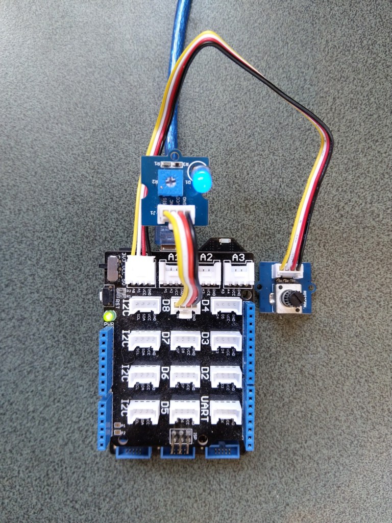
After some experimentation it appears that only A0 & A1 work on a Netduino. (Aug 2020).
My PWM test harness
public class Program
{
   public static void Main()
   {
      Debug.WriteLine("devMobile.Longboard.PwmTest starting");
      Debug.WriteLine(PwmController.GetDeviceSelector());

      try
      {
         PwmController pwm = PwmController.FromId("TIM5");
         AdcController adc = AdcController.GetDefault();
         AdcChannel adcChannel = adc.OpenChannel(0);

         PwmPin pwmPin = pwm.OpenPin(PinNumber('A', 0));
         pwmPin.Controller.SetDesiredFrequency(1000);
         pwmPin.Start();

         while (true)
         {
            double value = adcChannel.ReadRatio();

            Debug.WriteLine(value.ToString("F2"));

            pwmPin.SetActiveDutyCyclePercentage(value);

            Thread.Sleep(100);
         }
      }
      catch (Exception ex)
      {
         Debug.WriteLine(ex.Message);
      }
   }

   private static int PinNumber(char port, byte pin)
   {
      if (port < 'A' || port > 'J')
         throw new ArgumentException();
      return ((port - 'A') * 16) + pin;
   }
}
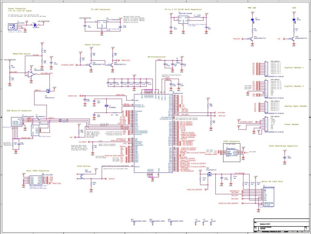
I had to refer to the Netduino schematic to figure out pin mapping
With my test rig (with easy access to D0 thru D8) I found that only D2,D3,D7 and D8 work as PWM outputs.
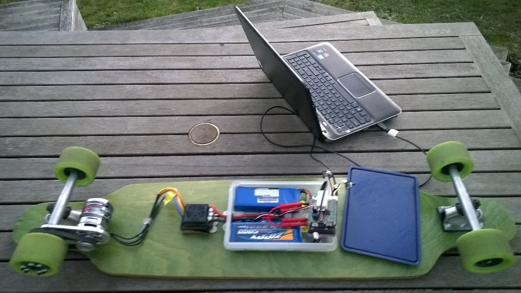
Roughly four years ago I build myself an electric longboard as summer transport. It initially had a controller built with a devDuino V2.2 which after a while I “upgraded” to a GHI Electronics.NET Microframework device.
Configuring the original netMF based longboard
Now that GHI Electronics no longer supports the FEZ Panda III I figured upgrading to a device that runs the nanoFramework would be a good compromise.
My changes were mainly related to the Inter Integrated Circuit(I2C) configuration and the reading+writing of registers.
/// <summary>
/// Initialises a new Wii Nunchuk
/// </summary>
/// <param name="busId">The unique identifier of the I²C to use.</param>
/// <param name="slaveAddress">The I²C address</param>
/// <param name="busSpeed">The bus speed, an enumeration that defaults to StandardMode</param>
/// <param name="sharingMode">The sharing mode, an enumeration that defaults to Shared.</param>
public WiiNunchuk(string busId, ushort slaveAddress = 0x52, I2cBusSpeed busSpeed = I2cBusSpeed.StandardMode, I2cSharingMode sharingMode = I2cSharingMode.Shared)
   {
      I2cTransferResult result;

      // This initialisation routine seems to work. I got it at http://wiibrew.org/wiki/Wiimote/Extension_Controllers#The_New_Way
      Device = I2cDevice.FromId(busId, new I2cConnectionSettings(slaveAddress)
      {
         BusSpeed = busSpeed,
         SharingMode = sharingMode,
      });

      result = Device.WritePartial(new byte[] { 0xf0, 0x55 });
      if (result.Status != I2cTransferStatus.FullTransfer)
      {
         throw new ApplicationException("Something went wrong reading the Nunchuk. Did you use proper pull-up resistors?");
      }

      result = Device.WritePartial(new byte[] { 0xfb, 0x00 });
      if (result.Status != I2cTransferStatus.FullTransfer)
      {
         throw new ApplicationException("Something went wrong reading the Nunchuk. Did you use proper pull-up resistors?");
      }

      this.Device.Write(new byte[] { 0xf0, 0x55 });
      this.Device.Write(new byte[] { 0xfb, 0x00 });
   }

   /// <summary>
   /// Reads all data from the nunchuk
   /// </summary>
   public void Read()
   {
      byte[] WaitWriteBuffer = { 0 };
      I2cTransferResult result;

      result = Device.WritePartial(WaitWriteBuffer);
      if (result.Status != I2cTransferStatus.FullTransfer)
      {
         throw new ApplicationException("Something went wrong reading the Nunchuk. Did you use proper pull-up resistors?");
      }

      byte[] ReadBuffer = new byte[6];
      result = Device.ReadPartial(ReadBuffer);
      if (result.Status != I2cTransferStatus.FullTransfer)
      {
         throw new ApplicationException("Something went wrong reading the Nunchuk. Did you use proper pull-up resistors?");
      }

      // Parses data according to http://wiibrew.org/wiki/Wiimote/Extension_Controllers/Nunchuck#Data_Format

      // Analog stick
      this.AnalogStickX = ReadBuffer[0];
      this.AnalogStickY = ReadBuffer[1];

      // Accelerometer
      ushort AX = (ushort)(ReadBuffer[2] << 2);
      ushort AY = (ushort)(ReadBuffer[3] << 2);
      ushort AZ = (ushort)(ReadBuffer[4] << 2);
      AZ += (ushort)((ReadBuffer[5] & 0xc0) >> 6); // 0xc0 = 11000000
      AY += (ushort)((ReadBuffer[5] & 0x30) >> 4); // 0x30 = 00110000
      AX += (ushort)((ReadBuffer[5] & 0x0c) >> 2); // 0x0c = 00001100
      this.AcceleroMeterX = AX;
      this.AcceleroMeterY = AY;
      this.AcceleroMeterZ = AZ;

      // Buttons
      ButtonC = (ReadBuffer[5] & 0x02) != 0x02;    // 0x02 = 00000010
      ButtonZ = (ReadBuffer[5] & 0x01) != 0x01;    // 0x01 = 00000001
}
The nanoFramework code polls for the joystick position and accelerometer values every 100mSec
public class Program
{
   public static void Main()
   {
      Debug.WriteLine("devMobile.Longboard.WiiNunchuckTest starting");
      Debug.WriteLine(I2cDevice.GetDeviceSelector());

      try
      {
         WiiNunchuk nunchuk = new WiiNunchuk("I2C1");

         while (true)
         {
            nunchuk.Read();

            Debug.WriteLine($"JoyX: {nunchuk.AnalogStickX} JoyY:{nunchuk.AnalogStickY} AX:{nunchuk.AcceleroMeterX} AY:{nunchuk.AcceleroMeterY} AZ:{nunchuk.AcceleroMeterZ} BtnC:{nunchuk.ButtonC} BtnZ:{nunchuk.ButtonZ}");

            Thread.Sleep(100);
         }
      }
      catch (Exception ex)
      {
         Debug.WriteLine(ex.Message);
      }
   }
}
The setup to use for the I2C port was determined by looking at the board.h and target_windows_devices_I2C_config.cpp file
//
// Copyright (c) 2018 The nanoFramework project contributors
// See LICENSE file in the project root for full license information.
//

#include <win_dev_i2c_native_target.h>

//////////
// I2C1 //
//////////

// pin configuration for I2C1
// port for SCL pin is: GPIOB
// port for SDA pin is: GPIOB
// SCL pin: is GPIOB_6
// SDA pin: is GPIOB_7
// GPIO alternate pin function is 4 (see alternate function mapping table in device datasheet)
I2C_CONFIG_PINS(1, GPIOB, GPIOB, 6, 7, 4)
Then checking this against the Netduino 3 Wifi schematic.
After some experimentation with how to detect if an I2C read or write had failed the debugging console output began displaying reasonable value
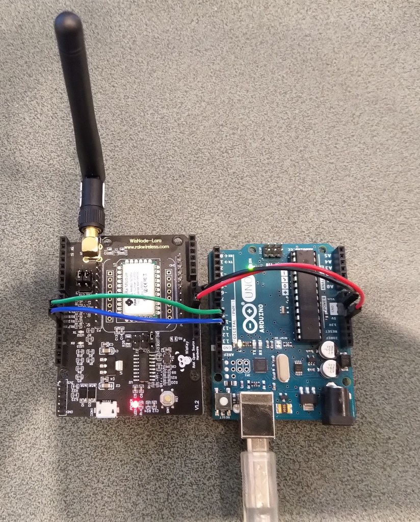
Just over a week ago I purchased a RAK811 LPWAN Evaluation Board -AS923 and now I want to trial it with selection of devices and configurations.
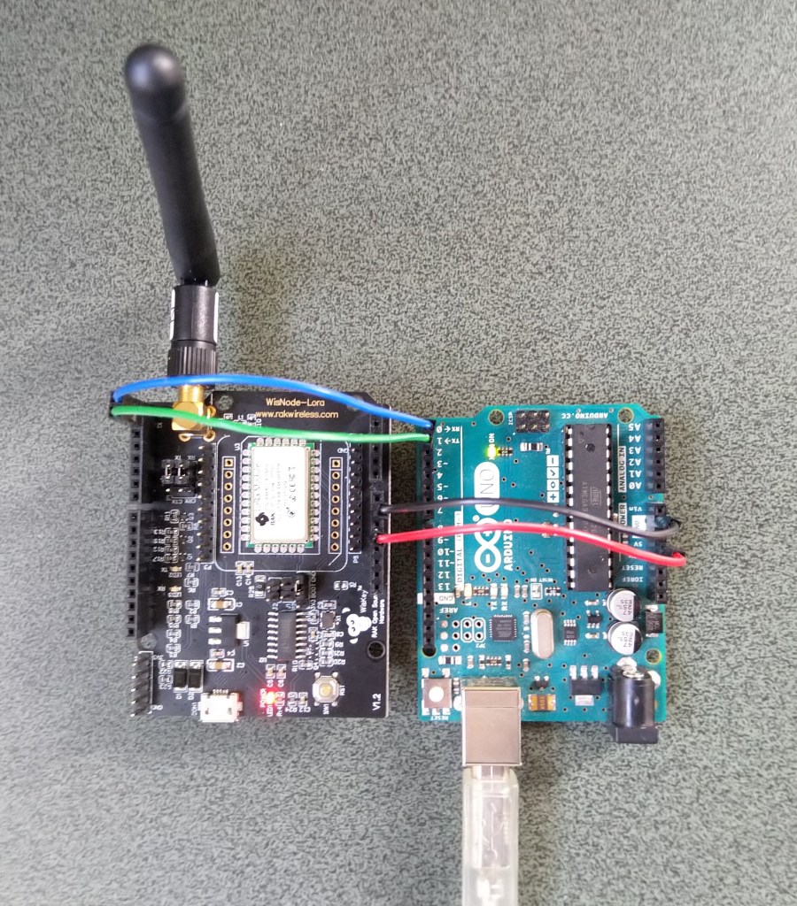
Initially I didn’t want to modify the shield by removing resistors as I only have one, and I’m not certain what device(s) it will be used with. The initial hardware configuration required jumpers for the serial port, ground and 5V power.
Arduino Uno R3 and RAK811 LPWAN Evaluation board 5V config
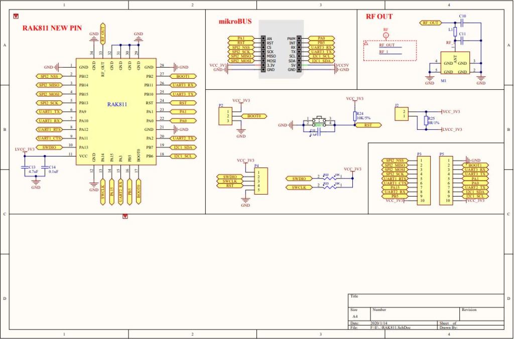
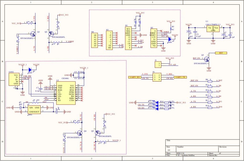
After looking at the schematic it should be possible to use the shield with a 3v3 device.
RAK 811 EVB schematic pg1RAK 811 EVB schematic pg2
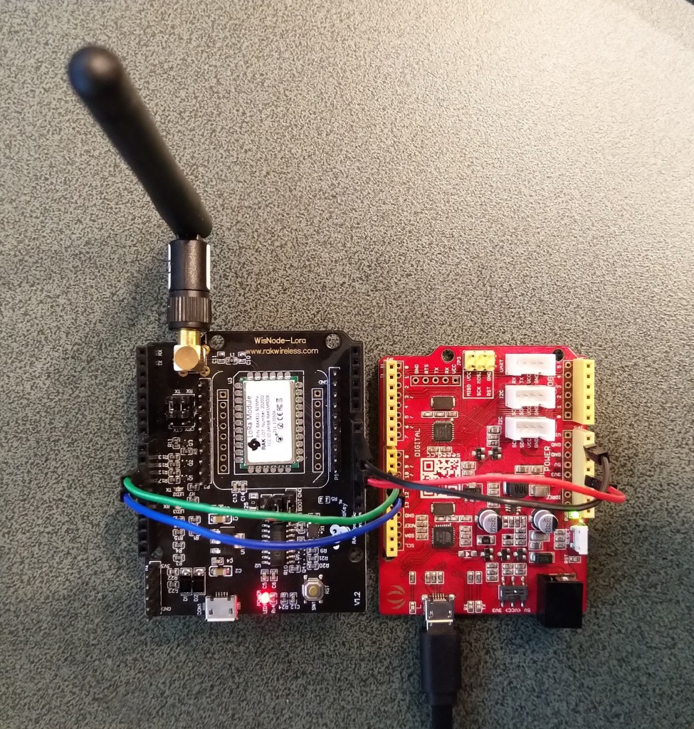
I confirmed this with a Seeeduino V4.2 devices set to 3v3, by putting a jumper on J1 and shifting the jumper wire from the 5V to the 3V3 pin.
Seeeduino V4 and RAK811 LPWAN Evaluation board 3V3 config
The next step was to see how I could get the RAK shield working on other devices without jumpers. On Arduino Uno R3 devices D0&D1 are the hardware(HW) serial port which are used for uploading sketches, and diagnostic logging.
The shield also connects the module serial port to D0&D1 to D10&D11, so by removing R17&R19 the shield should work on a device This would also allow the use of the Serial Peripheral Interface(SPI) port for other applications.
Using the HW Serial port but without any logging.
Unplugging the jumpers to upload was painful but the lack of logging made it really hard to debug my code.
To get around this I configured a SoftwareSerial port on D2&D3 for logging.
/********************************************************
* This demo is only supported after RUI firmware version 3.0.0.13.X on RAK811
* Master Board Uart Receive buffer size at least 128 bytes.
********************************************************/
//#define SERIAL_BUFFER_SIZE 128
//#define SERIAL_TX_BUFFER_SIZE 64
//#define SERIAL_RX_BUFFER_SIZE 128
//#define _SS_MAX_RX_BUFF 128
#include "RAK811.h"
#include "SoftwareSerial.h"
#define WORK_MODE LoRaWAN // LoRaWAN or LoRaP2P
#define JOIN_MODE OTAA // OTAA or ABP
#if JOIN_MODE == OTAA
String DevEui = "..."; // From TTN
String AppEui = "...";
String AppKey = "...";
#else JOIN_MODE == ABP
String NwkSKey = "...";
String AppSKey = "...";
String DevAddr = "...";
#endif
#define TXpin 3 // Set the virtual serial port pins
#define RXpin 2
SoftwareSerial DebugSerial(RXpin,TXpin); // Declare a virtual serial port for debugging
#define ATSerial Serial
char buffer[]= "48656C6C6F20776F726C6435";
bool InitLoRaWAN(void);
RAK811 RAKLoRa(ATSerial,DebugSerial);
void setup() {
DebugSerial.begin(19200);
DebugSerial.println(F("Starting"));
while(DebugSerial.available())
{
DebugSerial.read();
}
ATSerial.begin(9600); //set ATSerial baudrate:This baud rate has to be consistent with the baud rate of the WisNode device.
while(ATSerial.available())
{
ATSerial.read();
}
if(!RAKLoRa.rk_setWorkingMode(0)) //set WisNode work_mode to LoRaWAN.
{
DebugSerial.println(F("set work_mode failed, please reset module."));
while(1);
}
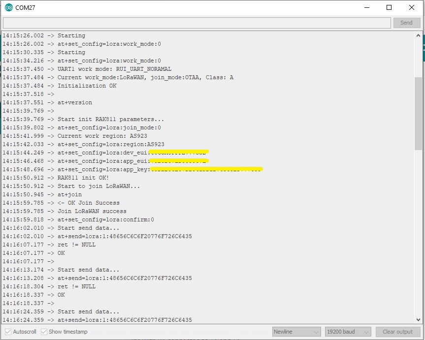
RAKLoRa.rk_getVersion(); //get RAK811 firmware version
DebugSerial.println(RAKLoRa.rk_recvData()); //print version number
DebugSerial.println(F("Start init RAK811 parameters..."));
if (!InitLoRaWAN()) //init LoRaWAN
{
DebugSerial.println(F("Init error,please reset module."));
while(1);
}
DebugSerial.println(F("Start to join LoRaWAN..."));
while(!RAKLoRa.rk_joinLoRaNetwork(60)) //Joining LoRaNetwork timeout 60s
{
DebugSerial.println();
DebugSerial.println(F("Rejoin again after 5s..."));
delay(5000);
}
DebugSerial.println(F("Join LoRaWAN success"));
if(!RAKLoRa.rk_isConfirm(0)) //set LoRa data send package type:0->unconfirm, 1->confirm
{
DebugSerial.println(F("LoRa data send package set error,please reset module."));
while(1);
}
}
bool InitLoRaWAN(void)
{
if(RAKLoRa.rk_setJoinMode(JOIN_MODE)) //set join_mode:OTAA
{
if(RAKLoRa.rk_setRegion(0)) //set region EU868
{
if (RAKLoRa.rk_initOTAA(DevEui, AppEui, AppKey))
{
DebugSerial.println(F("RAK811 init OK!"));
return true;
}
}
}
return false;
}
void loop()
{
DebugSerial.println(F("Start send data..."));
if (RAKLoRa.rk_sendData(1, buffer))
{
//for (unsigned long start = millis(); millis() - start < 300000L;)
for (unsigned long start = millis(); millis() - start < 10000L;)
{
String ret = RAKLoRa.rk_recvData();
if(ret != NULL)
{
DebugSerial.println("ret != NULL");
DebugSerial.println(ret);
}
if((ret.indexOf("OK")>0)||(ret.indexOf("ERROR")>0))
{
DebugSerial.println(F("Go to Sleep."));
RAKLoRa.rk_sleep(1); //Set RAK811 enter sleep mode
delay(10000); //delay 10s
RAKLoRa.rk_sleep(0); //Wakeup RAK811 from sleep mode
break;
}
}
}
}
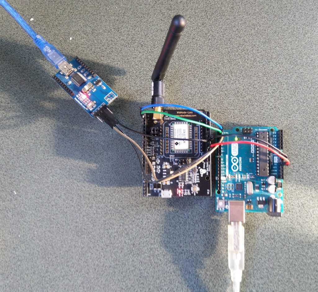
I used an FTDI module I had lying around to connect the diagnostic logging serial port on the test rig to my development box.
Using the HW Serial port but with logging.
Now I only had to unplug the jumpers for D0&D1 and change ports in the Arduino IDE. One port for debugging the other for downloading.
Depending on the application I may remove R8 so I can manually reset the shield.
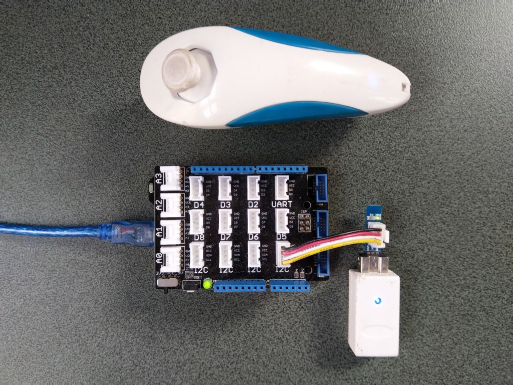
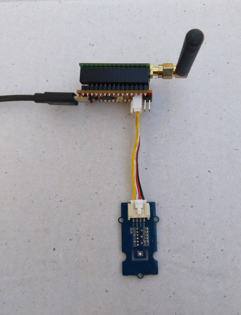
Seeeduino Nano easySensors shield and Grove VOC & eCO2 Sensor
Seeeduino Nano devices have a single on-board I2C socket which meant I didn’t need a Grove Shield for Arduino Nano which reduced the size and cost of the sensor node.
My first attempt failed with an issues accessing an Analog port to read the serial number from the Microchip ATSHA204 security chip. After looking at the Seeed SGP30 library source code (based on Sensiron samples) I think the my Nano device was running out of memory. I then searched for other Arduino compatible SGP30 libraries and rebuilt he application with the one from Sparkfun,
/*
  Copyright ® 2019 August devMobile Software, All Rights Reserved

  THIS CODE AND INFORMATION IS PROVIDED "AS IS" WITHOUT WARRANTY OF ANY
  KIND, EITHER EXPRESSED OR IMPLIED, INCLUDING BUT NOT LIMITED TO THE
  IMPLIED WARRANTIES OF MERCHANTABILITY AND/OR FITNESS FOR A PARTICULAR
  PURPOSE.

  You can do what you want with this code, acknowledgment would be nice.
  http://www.devmobile.co.nz

  Seeedstudio Grove - VOC and eCO2 Gas Sensor (SGP30)
  https://www.seeedstudio.com/Grove-VOC-and-eCO2-Gas-Sensor-SGP30-p-3071.html

  Seeeduino Nano
  https://www.seeedstudio.com/Seeeduino-Nano-p-4111.html

  Polycarbonate enclosure approx 3.5" x 4.5"
    2 x Cable glands
    1 x Grommet to seal SMA antenna connector
    3M command adhesive strips to hold battery & device in place

*/
#include <stdlib.h>
#include "SparkFun_SGP30_Arduino_Library.h"
#include <LoRa.h>
#include <sha204_library.h>

//#define DEBUG
//#define DEBUG_TELEMETRY
//#define DEBUG_LORA
#define DEBUG_VOC_AND_CO2

#define UNITS_VOC "ppb"
#define UNITS_CO2 "ppm"

// LoRa field gateway configuration (these settings must match your field gateway)
const byte DeviceAddressMaximumLength = 15 ;
const char FieldGatewayAddress[] = {"LoRaIoT1"};
const float FieldGatewayFrequency =  915000000.0;
const byte FieldGatewaySyncWord = 0x12 ;

// Payload configuration
const int ChipSelectPin = 10;
const int ResetPin = 9;
const int InterruptPin = 2;

// LoRa radio payload configuration
const byte SensorIdValueSeperator = ' ' ;
const byte SensorReadingSeperator = ',' ;
const unsigned long SensorUploadDelay = 60000;

// ATSHA204 secure authentication, validation with crypto and hashing (currently only using for unique serial number)
const byte Atsha204Port = A3;
atsha204Class sha204(Atsha204Port);
const byte DeviceSerialNumberLength = 9 ;
byte deviceSerialNumber[DeviceSerialNumberLength] = {""};

SGP30 mySensor; //create an object of the SGP30 class

const byte PayloadSizeMaximum = 64 ;
byte payload[PayloadSizeMaximum];
byte payloadLength = 0 ;


void setup()
{
  Serial.begin(9600);

#ifdef DEBUG
  while (!Serial);
#endif

  Serial.println("Setup called");

  Serial.print("Field gateway:");
  Serial.print(FieldGatewayAddress ) ;
  Serial.print(" Frequency:");
  Serial.print( FieldGatewayFrequency,0 ) ;
  Serial.print("MHz SyncWord:");
  Serial.print( FieldGatewaySyncWord ) ;
  Serial.println();

   // Retrieve the serial number then display it nicely
  if(sha204.getSerialNumber(deviceSerialNumber))
  {
    Serial.println("sha204.getSerialNumber failed");
    while (true); // Drop into endless loop requiring restart
  }

  Serial.print("SNo:");
  DisplayHex( deviceSerialNumber, DeviceSerialNumberLength);
  Serial.println();

  Serial.println("LoRa setup start");

  // override the default chip select and reset pins
  LoRa.setPins(ChipSelectPin, ResetPin, InterruptPin);
  if (!LoRa.begin(FieldGatewayFrequency))
  {
    Serial.println("LoRa begin failed");
    while (true); // Drop into endless loop requiring restart
  }

  // Need to do this so field gateway pays attention to messsages from this device
  LoRa.enableCrc();
  LoRa.setSyncWord(FieldGatewaySyncWord);

#ifdef DEBUG_LORA
  LoRa.dumpRegisters(Serial);
#endif
  Serial.println("LoRa Setup done.");

  // Configure the DF Robot SHT20, temperature & humidity sensor
  Serial.println("SGP30 setup start");
  Wire.begin();
  if(mySensor.begin() == false)
  {
    Serial.println("SQP-30 initialisation failed");
    while (true); // Drop into endless loop requiring restart
  }
  mySensor.initAirQuality();
  delay(1000);
  Serial.println("SGP30 setup done");

  PayloadHeader((byte *)FieldGatewayAddress,strlen(FieldGatewayAddress), deviceSerialNumber, DeviceSerialNumberLength);

  Serial.println("Setup done");
  Serial.println();
}


void loop()
{
  unsigned long currentMilliseconds = millis();

  Serial.println("Loop called");

  mySensor.measureAirQuality();

  PayloadReset();

  PayloadAdd( "v", mySensor.TVOC, false);

  PayloadAdd( "c", mySensor.CO2, false);

  #ifdef DEBUG_VOC_AND_CO2
    Serial.print("VoC:");
    Serial.print( mySensor.TVOC ) ;
    Serial.print( UNITS_VOC ) ;
    Serial.print(" Co2:");
    Serial.print( mySensor.CO2 ) ;
    Serial.println( UNITS_CO2 ) ;
  #endif

  #ifdef DEBUG_TELEMETRY
    Serial.println();
    Serial.print("RFM9X/SX127X Payload length:");
    Serial.print(payloadLength);
    Serial.println(" bytes");
  #endif

  LoRa.beginPacket();
  LoRa.write(payload, payloadLength);
  LoRa.endPacket();

  Serial.println("Loop done");
  Serial.println();

  delay(SensorUploadDelay - (millis() - currentMilliseconds ));
}


void PayloadHeader( const byte *to, byte toAddressLength, const byte *from, byte fromAddressLength)
{
  byte addressesLength = toAddressLength + fromAddressLength ;

  payloadLength = 0 ;

  // prepare the payload header with "To" Address length (top nibble) and "From" address length (bottom nibble)

  payload[payloadLength] = (toAddressLength << 4) | fromAddressLength ;
  payloadLength += 1;

  // Copy the "To" address into payload
  memcpy(&payload[payloadLength], to, toAddressLength);
  payloadLength += toAddressLength ;

  // Copy the "From" into payload
  memcpy(&payload[payloadLength], from, fromAddressLength);
  payloadLength += fromAddressLength ;
}


void PayloadAdd( const char *sensorId, float value, byte decimalPlaces, bool last)
{
  byte sensorIdLength = strlen( sensorId ) ;

  memcpy( &payload[payloadLength], sensorId,  sensorIdLength) ;
  payloadLength += sensorIdLength ;
  payload[ payloadLength] = SensorIdValueSeperator;
  payloadLength += 1 ;
  payloadLength += strlen( dtostrf(value, -1, decimalPlaces, (char *)&payload[payloadLength]));
  if (!last)
  {
    payload[ payloadLength] = SensorReadingSeperator;
    payloadLength += 1 ;
  }

#ifdef DEBUG_TELEMETRY
  Serial.print("PayloadAdd float-payloadLength:");
  Serial.print( payloadLength);
  Serial.println( );
#endif
}


void PayloadAdd( char *sensorId, int value, bool last )
{
  byte sensorIdLength = strlen(sensorId) ;

  memcpy(&payload[payloadLength], sensorId,  sensorIdLength) ;
  payloadLength += sensorIdLength ;
  payload[ payloadLength] = SensorIdValueSeperator;
  payloadLength += 1 ;
  payloadLength += strlen(itoa( value,(char *)&payload[payloadLength],10));
  if (!last)
  {
    payload[ payloadLength] = SensorReadingSeperator;
    payloadLength += 1 ;
  }

#ifdef DEBUG_TELEMETRY
  Serial.print("PayloadAdd int-payloadLength:" );
  Serial.print(payloadLength);
  Serial.println( );
#endif
}


void PayloadAdd( char *sensorId, unsigned int value, bool last )
{
  byte sensorIdLength = strlen(sensorId) ;

  memcpy(&payload[payloadLength], sensorId,  sensorIdLength) ;
  payloadLength += sensorIdLength ;
  payload[ payloadLength] = SensorIdValueSeperator;
  payloadLength += 1 ;
  payloadLength += strlen(utoa( value,(char *)&payload[payloadLength],10));
  if (!last)
  {
    payload[ payloadLength] = SensorReadingSeperator;
    payloadLength += 1 ;
  }

#ifdef DEBUG_TELEMETRY
  Serial.print("PayloadAdd uint-payloadLength:");
  Serial.print(payloadLength);
  Serial.println( );
#endif
}


void PayloadReset()
{
  byte fromAddressLength = payload[0] & 0xf ;
  byte toAddressLength = payload[0] >> 4 ;

  payloadLength = toAddressLength + fromAddressLength + 1;
}


void DisplayHex( byte *byteArray, byte length)
{
  for (int i = 0; i < length ; i++)
  {
    // Add a leading zero
    if ( byteArray[i] < 16)
    {
      Serial.print("0");
    }
    Serial.print(byteArray[i], HEX);
    if ( i < (length-1)) // Don't put a - after last digit
    {
      Serial.print("-");
    }
  }
}
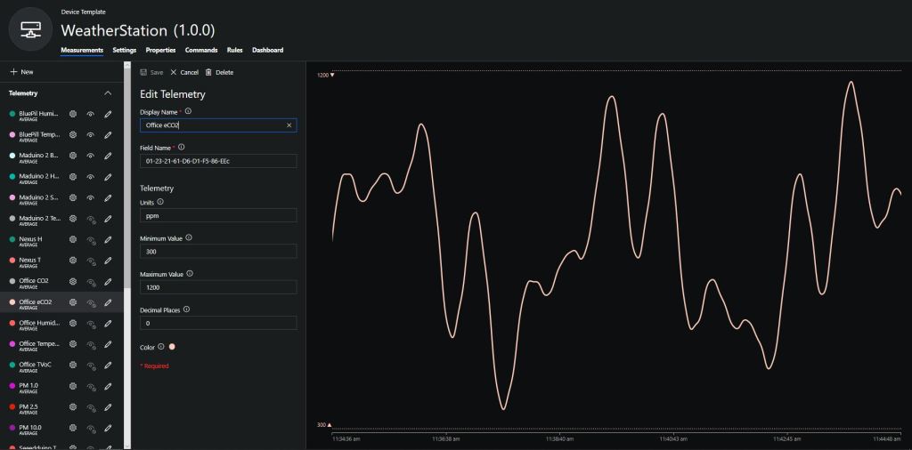
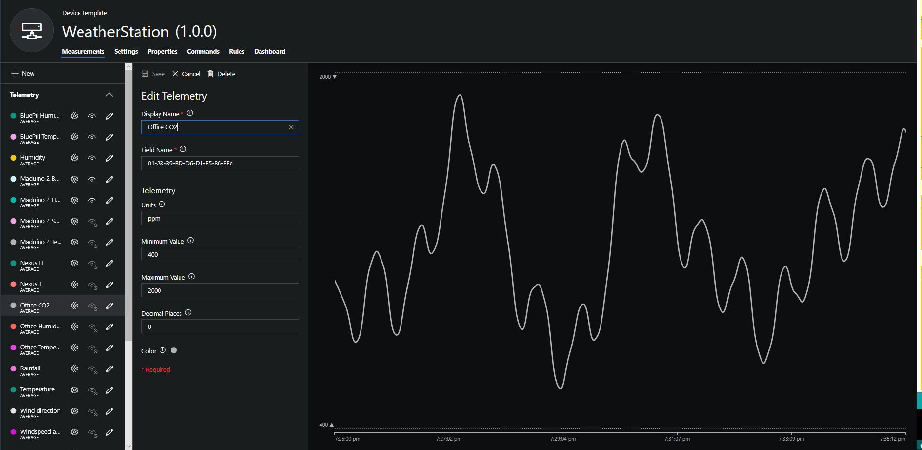
To configure the device in Azure IoT Central (similar process for Adafruit.IO, working on support for losant, and ubidots) I copied the SNo: from the Arduino development tool logging window and appended c for the CO2 parts per million (ppm), v for VOC parts per billion (ppb) unique serial number from the ATSHA204A chip. (N.B. pay attention to the case of the field names they are case sensitive)
Azure IoT Central configuration
Overall the performance of the VoC sensor data is looking pretty positive, the eCO2 readings need some further investigation as they track the VOC levels. The large spike in the graph below is me putting an open vivid marker on my desk near the sensor.
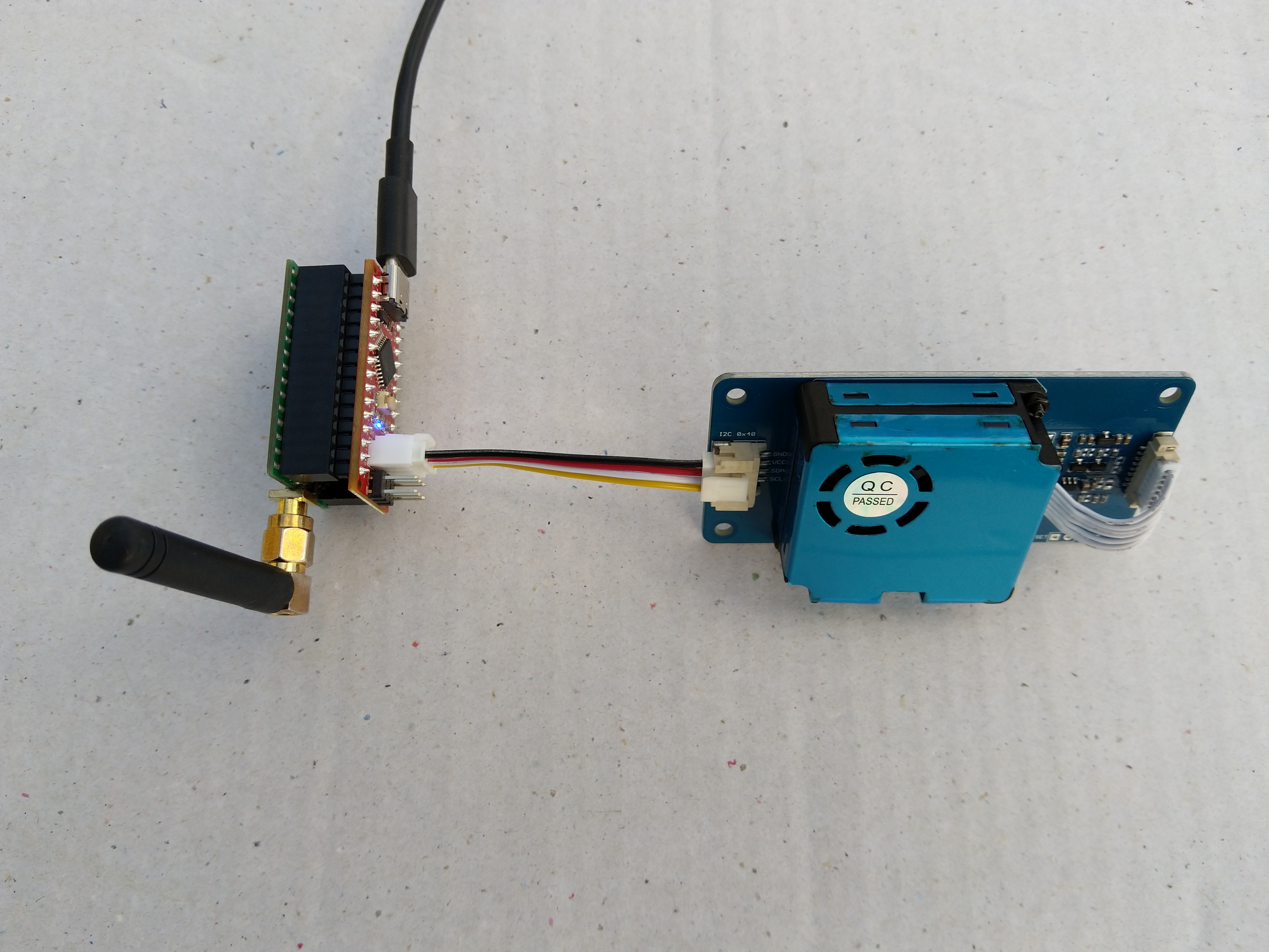
Seeeduino Nano, EasySensors Shield & DF Robot Sensor test rig
The Seeeduino Nano devices I’m testing have a single on-board I2C socket which meant I didn’t need a Grove Shield for Arduino Nano which reduced the size and cost of the sensor node.
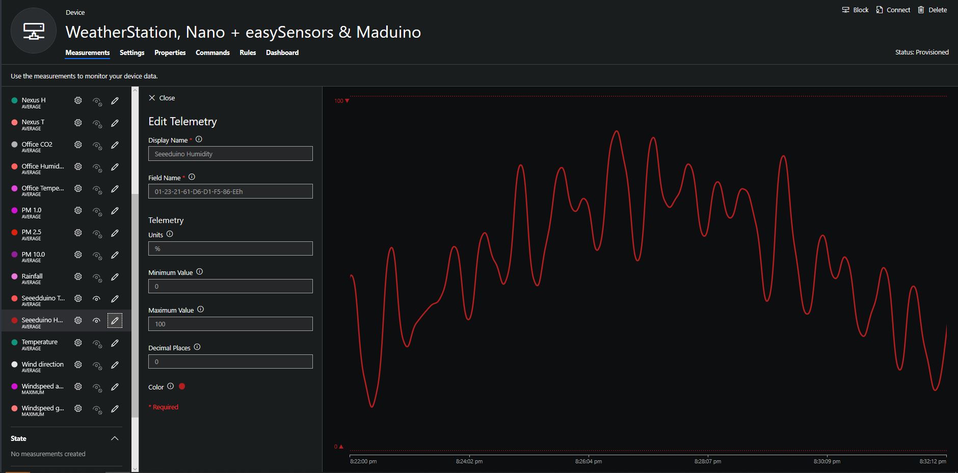
To configure the device in Azure IoT Central (similar process for Adafruit.IO, working on support for losant,and ubidots I copied the SNo: from the Arduino development tool logging window and appended p10 for PM 1 value, p25 for PM2.5 value and p100 for PM10 value to the unique serial number from the ATSHA204A chip. (N.B. pay attention to the case of the field names they are case sensitive)
When I moved the sensor indoors it appeared to take a while to warm up and after a while the metal body still felt cold. The sensor element is surrounded by quite a bit of protective packaging for outdoors use and I that would have a bit more thermal inertia the than the lightweight indoor enclosure.
It would be good to run the sensor alongside a calibrated temperature & humidity sensor to see how accurate and responsive it is.
The Seeeduino Nano devices I’m testing have a single on-board I2C socket which meant I didn’t need a Grove Shield for Arduino Nano which reduced the size and cost of the sensor node.
After looking at the demo application I stripped out the checksum code and threw the rest away. In my test harness I have extracted only the PM1.0/PM2.5/PM10.0 (concentration CF=1, Standard particulate) in μg/ m3 values from the sensor response payload.
/*
  Copyright ® 2019 August devMobile Software, All Rights Reserved

  THIS CODE AND INFORMATION IS PROVIDED "AS IS" WITHOUT WARRANTY OF ANY
  KIND, EITHER EXPRESSED OR IMPLIED, INCLUDING BUT NOT LIMITED TO THE
  IMPLIED WARRANTIES OF MERCHANTABILITY AND/OR FITNESS FOR A PARTICULAR
  PURPOSE.

  You can do what you want with this code, acknowledgment would be nice.

  http://www.devmobile.co.nz

*/
#include <stdlib.h>
#include <LoRa.h>
#include <sha204_library.h>
#include "Seeed_HM330X.h"

//#define DEBUG
//#define DEBUG_TELEMETRY
//#define DEBUG_LORA

const byte SensorPayloadLength = 28 ;
const byte SensorPayloadBufferSize  = 29 ;
const byte SensorPayloadPM1_0Position = 4;
const byte SensorPayloadPM2_5Position = 6;
const byte SensorPayloadPM10_0Position = 8;

HM330X sensor;
byte SensorPayload[SensorPayloadBufferSize];

// LoRa field gateway configuration (these settings must match your field gateway)
const byte DeviceAddressMaximumLength = 15 ;
const char FieldGatewayAddress[] = {"LoRaIoT1"};
const float FieldGatewayFrequency =  915000000.0;
const byte FieldGatewaySyncWord = 0x12 ;

// Payload configuration
const int ChipSelectPin = 10;
const int ResetPin = 9;
const int InterruptPin = 2;

// LoRa radio payload configuration
const byte SensorIdValueSeperator = ' ' ;
const byte SensorReadingSeperator = ',' ;
const unsigned long SensorUploadDelay = 60000;

// ATSHA204 secure authentication, validation with crypto and hashing (currently only using for unique serial number)
const byte Atsha204Port = A3;
atsha204Class sha204(Atsha204Port);
const byte DeviceSerialNumberLength = 9 ;
byte deviceSerialNumber[DeviceSerialNumberLength] = {""};

const byte PayloadSizeMaximum = 64 ;
byte payload[PayloadSizeMaximum];
byte payloadLength = 0 ;


void setup()
{
  Serial.begin(9600);

#ifdef DEBUG
  while (!Serial);
#endif

  Serial.println("Setup called");

  Serial.print("Field gateway:");
  Serial.print(FieldGatewayAddress ) ;
  Serial.print(" Frequency:");
  Serial.print( FieldGatewayFrequency,0 ) ;
  Serial.print("MHz SyncWord:");
  Serial.print( FieldGatewaySyncWord ) ;
  Serial.println();

   // Retrieve the serial number then display it nicely
  if(sha204.getSerialNumber(deviceSerialNumber))
  {
    Serial.println("sha204.getSerialNumber failed");
    while (true); // Drop into endless loop requiring restart
  }

  Serial.print("SNo:");
  DisplayHex( deviceSerialNumber, DeviceSerialNumberLength);
  Serial.println();

  Serial.println("LoRa setup start");

  // override the default chip select and reset pins
  LoRa.setPins(ChipSelectPin, ResetPin, InterruptPin);
  if (!LoRa.begin(FieldGatewayFrequency))
  {
    Serial.println("LoRa begin failed");
    while (true); // Drop into endless loop requiring restart
  }

  // Need to do this so field gateway pays attention to messsages from this device
  LoRa.enableCrc();
  LoRa.setSyncWord(FieldGatewaySyncWord);

#ifdef DEBUG_LORA
  LoRa.dumpRegisters(Serial);
#endif
  Serial.println("LoRa Setup done.");

  // Configure the Seeedstudio CO2, temperature & humidity sensor
  Serial.println("HM3301 setup start");
  if(sensor.init())
  {
    Serial.println("HM3301 init failed");
    while (true); // Drop into endless loop requiring restart

  }
  delay(100);
  Serial.println("HM3301 setup done");

  PayloadHeader((byte *)FieldGatewayAddress,strlen(FieldGatewayAddress), deviceSerialNumber, DeviceSerialNumberLength);

  Serial.println("Setup done");
  Serial.println();
}

void loop()
{
  unsigned long currentMilliseconds = millis();
  byte sum=0;
  short pm1_0 ;
  short pm2_5 ;
  short pm10_0 ;

  Serial.println("Loop called");

  if(sensor.read_sensor_value(SensorPayload,SensorPayloadBufferSize) == NO_ERROR)
  {
    // Calculate then validate the payload "checksum"
    for(int i=0;i<SensorPayloadLength;i++)
    {
        sum+=SensorPayload[i];
    }
    if(sum!=SensorPayload[SensorPayloadLength])
    {
        Serial.println("Invalid checksum");
        return;
    }

    PayloadReset();

    pm1_0 = (u16)SensorPayload[SensorPayloadPM1_0Position]<<8|SensorPayload[SensorPayloadPM1_0Position+1];
    Serial.print("PM1.5: ");
    Serial.print(pm1_0);
    Serial.println("ug/m3 ") ;

    PayloadAdd( "P10", pm1_0, false);

    pm2_5 = (u16)SensorPayload[SensorPayloadPM2_5Position]<<8|SensorPayload[SensorPayloadPM2_5Position+1];
    Serial.print("PM2.5: ");
    Serial.print(pm2_5);
    Serial.println("ug/m3 ") ;

    PayloadAdd( "P25", pm2_5, 1, false);

    pm10_0 = (u16)SensorPayload[SensorPayloadPM10_0Position]<<8|SensorPayload[SensorPayloadPM10_0Position+1];
    Serial.print("PM10.0: ");
    Serial.print(pm10_0);
    Serial.println("ug/m3 ");

    PayloadAdd( "P100", pm10_0, 0, true) ;

    #ifdef DEBUG_TELEMETRY
      Serial.println();
      Serial.print("RFM9X/SX127X Payload length:");
      Serial.print(payloadLength);
      Serial.println(" bytes");
    #endif

    LoRa.beginPacket();
    LoRa.write(payload, payloadLength);
    LoRa.endPacket();
  }
  Serial.println("Loop done");
  Serial.println();

  delay(SensorUploadDelay - (millis() - currentMilliseconds ));
}

void PayloadHeader( const byte *to, byte toAddressLength, const byte *from, byte fromAddressLength)
{
  byte addressesLength = toAddressLength + fromAddressLength ;

  payloadLength = 0 ;

  // prepare the payload header with "To" Address length (top nibble) and "From" address length (bottom nibble)

  payload[payloadLength] = (toAddressLength << 4) | fromAddressLength ;
  payloadLength += 1;

  // Copy the "To" address into payload
  memcpy(&payload[payloadLength], to, toAddressLength);
  payloadLength += toAddressLength ;

  // Copy the "From" into payload
  memcpy(&payload[payloadLength], from, fromAddressLength);
  payloadLength += fromAddressLength ;
}

void PayloadAdd( const char *sensorId, float value, byte decimalPlaces, bool last)
{
  byte sensorIdLength = strlen( sensorId ) ;

  memcpy( &payload[payloadLength], sensorId,  sensorIdLength) ;
  payloadLength += sensorIdLength ;
  payload[ payloadLength] = SensorIdValueSeperator;
  payloadLength += 1 ;
  payloadLength += strlen( dtostrf(value, -1, decimalPlaces, (char *)&payload[payloadLength]));
  if (!last)
  {
    payload[ payloadLength] = SensorReadingSeperator;
    payloadLength += 1 ;
  }

#ifdef DEBUG_TELEMETRY
  Serial.print("PayloadAdd float-payloadLength:");
  Serial.print( payloadLength);
  Serial.println( );
#endif
}

void PayloadAdd( char *sensorId, int value, bool last )
{
  byte sensorIdLength = strlen(sensorId) ;

  memcpy(&payload[payloadLength], sensorId,  sensorIdLength) ;
  payloadLength += sensorIdLength ;
  payload[ payloadLength] = SensorIdValueSeperator;
  payloadLength += 1 ;
  payloadLength += strlen(itoa( value,(char *)&payload[payloadLength],10));
  if (!last)
  {
    payload[ payloadLength] = SensorReadingSeperator;
    payloadLength += 1 ;
  }

#ifdef DEBUG_TELEMETRY
  Serial.print("PayloadAdd int-payloadLength:" );
  Serial.print(payloadLength);
  Serial.println( );
#endif
}

void PayloadAdd( char *sensorId, unsigned int value, bool last )
{
  byte sensorIdLength = strlen(sensorId) ;

  memcpy(&payload[payloadLength], sensorId,  sensorIdLength) ;
  payloadLength += sensorIdLength ;
  payload[ payloadLength] = SensorIdValueSeperator;
  payloadLength += 1 ;
  payloadLength += strlen(utoa( value,(char *)&payload[payloadLength],10));
  if (!last)
  {
    payload[ payloadLength] = SensorReadingSeperator;
    payloadLength += 1 ;
  }

#ifdef DEBUG_TELEMETRY
  Serial.print("PayloadAdd uint-payloadLength:");
  Serial.print(payloadLength);
  Serial.println( );
#endif
}

void PayloadReset()
{
  byte fromAddressLength = payload[0] & 0xf ;
  byte toAddressLength = payload[0] >> 4 ;

  payloadLength = toAddressLength + fromAddressLength + 1;
}

void DisplayHex( byte *byteArray, byte length)
{
  for (int i = 0; i < length ; i++)
  {
    // Add a leading zero
    if ( byteArray[i] < 16)
    {
      Serial.print("0");
    }
    Serial.print(byteArray[i], HEX);
    if ( i < (length-1)) // Don't put a - after last digit
    {
      Serial.print("-");
    }
  }
}
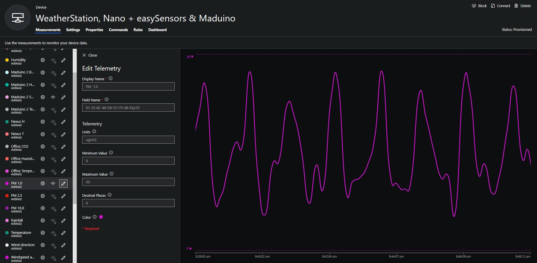
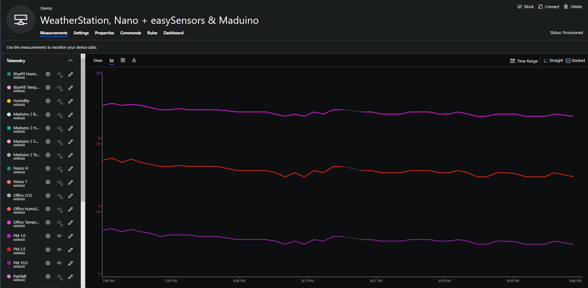
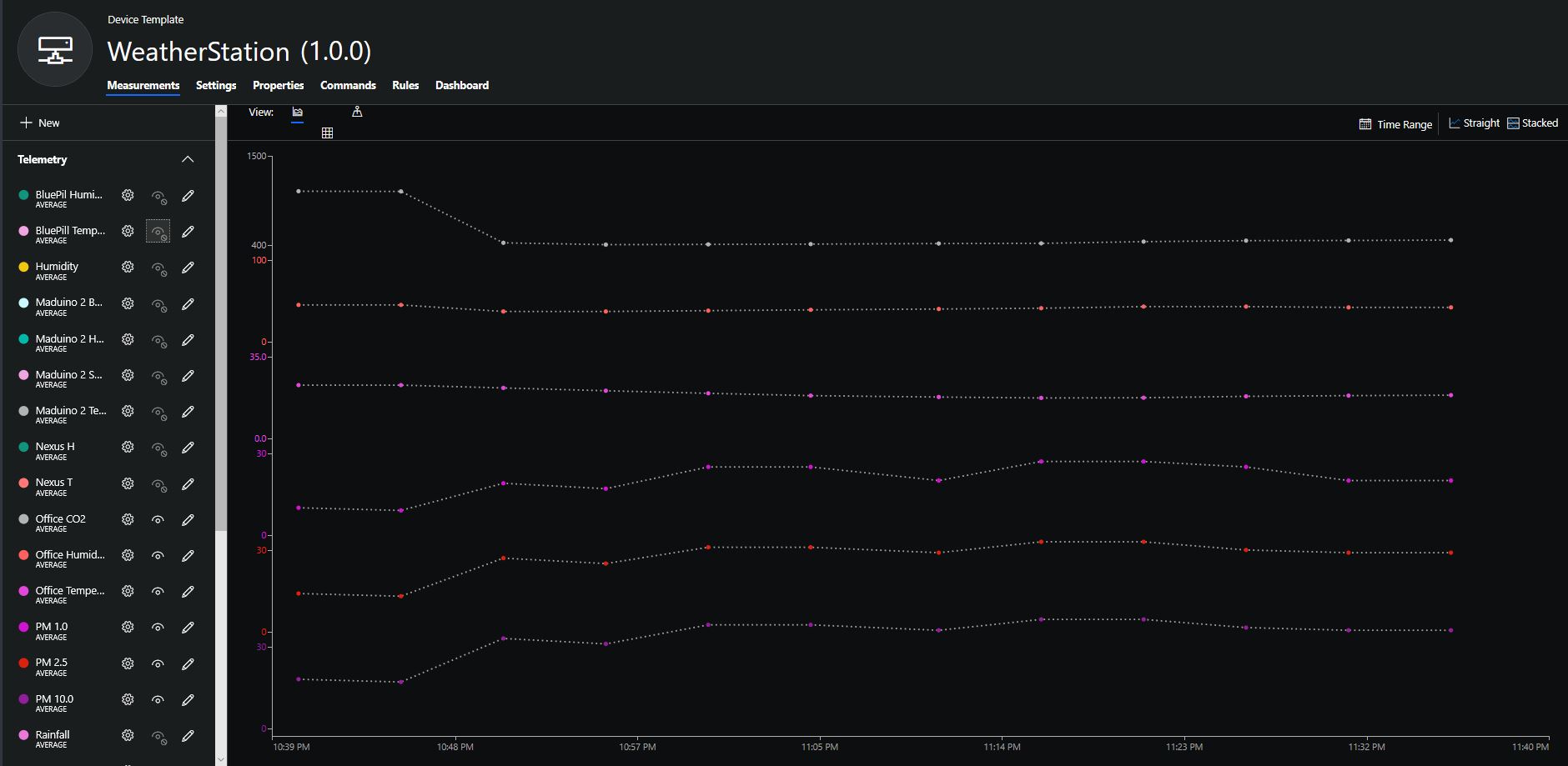
To configure the device in Azure IoT Central (similar process for Adafruit.IO, working on support for losant, and ubidots) I copied the SNo: from the Arduino development tool logging window and appended p10 for PM 1 value, p25 for PM2.5 value and p100 for PM10 value to the unique serial number from the ATSHA204A chip. (N.B. pay attention to the case of the field names they are case sensitive)
Azure IoT Central telemetry configuration
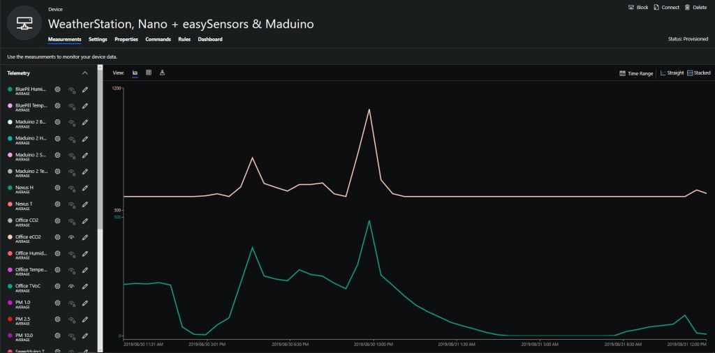
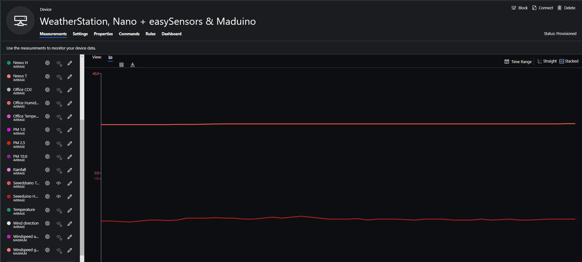
The rapidly settled into a narrow range of readings, but spiked when I took left it outside (winter in New Zealand) and the values spiked when food was being cooked in the kitchen which is next door to my office.
It would be good to run the sensor alongside a professional particulates monitor so the values could be compared and used to adjust the readings of the Grove sensor if necessary.
Hour of PM1, PM2.5 & PM10 readings in my office early eveningCO2 and particulates values while outside on my deck from 10:30pm to 11:30pm
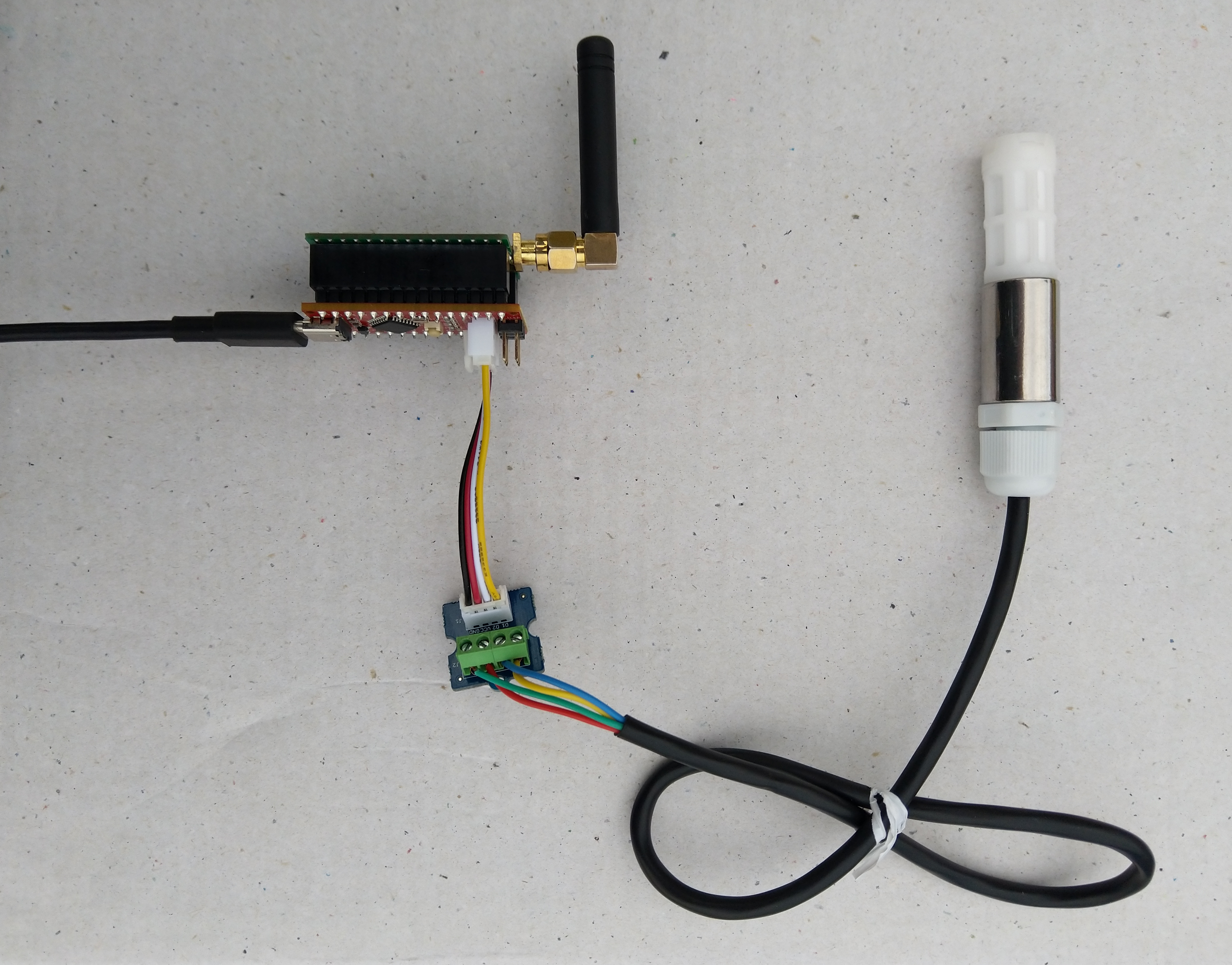
Seeeduino Nano devices have a single on-board I2C socket which meant I didn’t need a Grove Shield for Arduino Nano which reduced the size and cost of the sensor node.
I downloaded the seeedstudio wiki example calibration code, compiled and uploaded it to one of my Seeeduino Nano devices. When activated for the first time a period of minimum 7 days is needed so that the sensor algorithm can find its initial parameter set. During this period the sensor has to be exposed to fresh air for at least 1 hour every day.
During the calibration process I put the device in my garage and left the big door open for at least an hour every day. Once the sensor was calibrated I bought it inside at put it on the bookcase in my office.
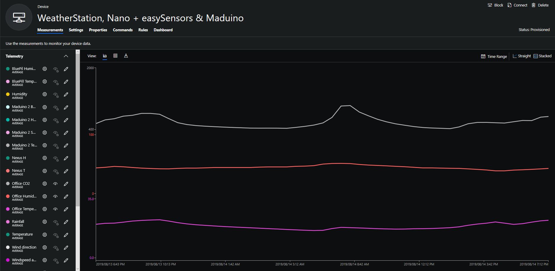
To configure the device in Azure IoT Central (similar process for Adafruit.IO, working on support for losant, and ubidots) I copied the SNo: from the Arduino development tool logging window and appended c for the CO2 parts per million (ppm), h for the humidity % and t for the temperature °C to the unique serial number from the ATSHA204A chip. (N.B. pay attention to the case of the field names they are case sensitive)
Azure IoT Central telemetry configuration
Overall the performance of the sensor is looking pretty positive, the CO2 levels fluctuate in a acceptable range (based on office occupancy), and the temperature + humidity readings track quite closely to the other two sensor nodes in my office. The only issue so far is my lack of USB-C cables to power the devices in the field
CO2, Humidity and Temperature in my office for a day
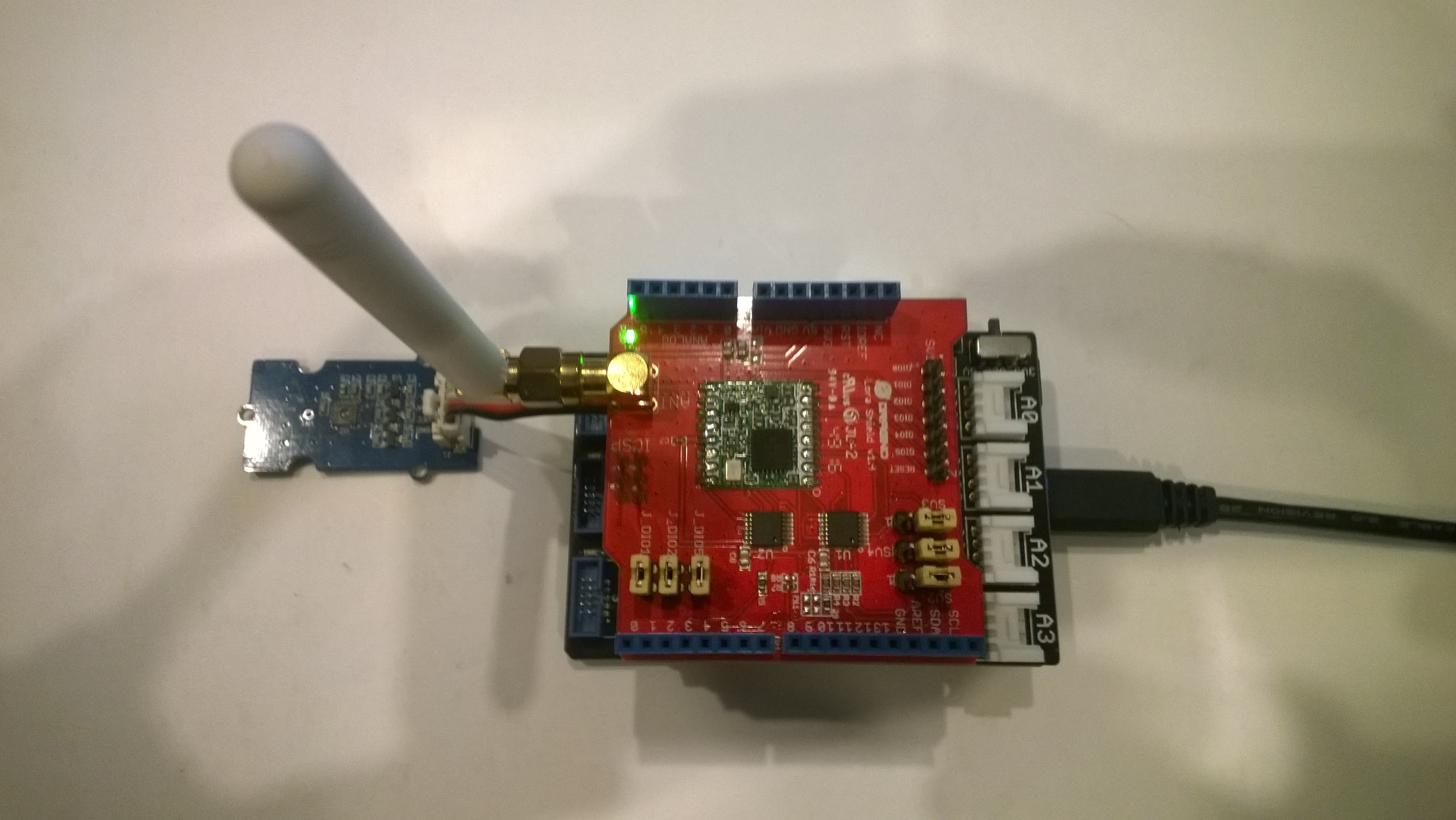
Thought the silk screen says RFM69 this is a prototype running an RFM95 module.
Bill of materials (Prices Sep 2018)
IoT.Net device (Beta tester will add price when available)
The device has an onboard MCP9808temperature sensor which kept the BoM really short. I have had to make some modifications to my RFM9XLoRaNetMF library as the IoT.Net device uses a different SPI port. The code for this devices and the changes will be uploaded to GitHub in the next couple of days.
//---------------------------------------------------------------------------------
// Copyright (c) Sept 2018, devMobile Software
//
// Licensed under the Apache License, Version 2.0 (the "License");
// you may not use this file except in compliance with the License.
// You may obtain a copy of the License at
//
//     http://www.apache.org/licenses/LICENSE-2.0
//
// Unless required by applicable law or agreed to in writing, software
// distributed under the License is distributed on an "AS IS" BASIS,
// WITHOUT WARRANTIES OR CONDITIONS OF ANY KIND, either express or implied.
// See the License for the specific language governing permissions and
// limitations under the License.
// git remote add origin https://github.com/KiwiBryn/FieldGateway.LoRa.IoTNetClient.git
// git push -u origin master
//---------------------------------------------------------------------------------
namespace devMobile.IoT.IoTNet.FieldGateway
{
	using System;
	using System.Text;
	using System.Threading;
	using Microsoft.SPOT;
	using Microsoft.SPOT.Hardware;
	using devMobile.IoT.NetMF.ISM;
	using IngenuityMicro.Sensors;

	class IoTNetClient
	{
		private readonly Rfm9XDevice rfm9XDevice;
		private readonly TimeSpan dueTime = new TimeSpan(0, 0, 10);
		private readonly TimeSpan periodTime = new TimeSpan(0, 0, 30);
		private readonly MCP9808 mcp9808 = new MCP9808();
		private readonly OutputPort _led = new OutputPort((Cpu.Pin)16 + 8, false);
		private readonly byte[] fieldGatewayAddress = Encoding.UTF8.GetBytes("LoRaIoT1");
		private readonly byte[] deviceAddress = Encoding.UTF8.GetBytes("IoTNet1");

		public IoTNetClient()
		{
			rfm9XDevice = new Rfm9XDevice( SPI.SPI_module.SPI3, (Cpu.Pin)16 + 9, (Cpu.Pin)5, (Cpu.Pin)4);
		}

		public void Run()
		{
			rfm9XDevice.Initialise(frequency: 915000000, paBoost: true, rxPayloadCrcOn: true);
			rfm9XDevice.Receive(deviceAddress);

			rfm9XDevice.OnDataReceived += rfm9XDevice_OnDataReceived;
			rfm9XDevice.OnTransmit += rfm9XDevice_OnTransmit;

			Timer temperatureUpdates = new Timer(TemperatureTimerProc, null, dueTime, periodTime);

			Thread.Sleep(Timeout.Infinite);
		}

		private void TemperatureTimerProc(object state)
		{
			_led.Write(true);

			double temperature = mcp9808.ReadTempInC();

			Debug.Print(DateTime.UtcNow.ToString("hh:mm:ss") + "  T:" + temperature.ToString("F1"));

			rfm9XDevice.Send(fieldGatewayAddress, Encoding.UTF8.GetBytes("t " + temperature.ToString("F1")));

			_led.Write(true);
		}

		void rfm9XDevice_OnTransmit()
		{
			Debug.Print("Transmit-Done");
			_led.Write(false);
		}

		void rfm9XDevice_OnDataReceived(byte[] address, float packetSnr, int packetRssi, int rssi, byte[] data)
		{
			try
			{
				string messageText = new string(UTF8Encoding.UTF8.GetChars(data));
				string addressText = new string(UTF8Encoding.UTF8.GetChars(address));

				Debug.Print(DateTime.UtcNow.ToString("HH:MM:ss") + "-Rfm9X PacketSnr " + packetSnr.ToString("F1") + " Packet RSSI " + packetRssi + "dBm RSSI " + rssi + "dBm = " + data.Length + " byte message " + @"""" + messageText + @"""");
			}
			catch (Exception ex)
			{
				Debug.Print(ex.Message);
			}
		}
	}
}
}
.Net Framework debug output Field Gateway
22:55:39-RX From IoTNet1 PacketSnr 9.5 Packet RSSI -50dBm RSSI -110dBm = 6 byte message "t 23.6"
 Sensor IoTNet1t Value 23.6
 AzureIoTHubClient SendEventAsync start
 AzureIoTHubClient SendEventAsync finish
The thread 0xbec has exited with code 0 (0x0).
The thread 0xbb4 has exited with code 0 (0x0).
The thread 0xa0c has exited with code 0 (0x0).
The thread 0x13c has exited with code 0 (0x0).
22:56:09-RX From IoTNet1 PacketSnr 9.3 Packet RSSI -44dBm RSSI -102dBm = 6 byte message "t 23.8"
 Sensor IoTNet1t Value 23.8
 AzureIoTHubClient SendEventAsync start
 AzureIoTHubClient SendEventAsync finish
A small footprint, battery powered .NetMF 4.4 LoRa device designed and made in New Zealand with Visual Studio 2017 support is great.
//---------------------------------------------------------------------------------
// Copyright (c) 2017, devMobile Software
//
// Licensed under the Apache License, Version 2.0 (the "License");
// you may not use this file except in compliance with the License.
// You may obtain a copy of the License at
//
//     http://www.apache.org/licenses/LICENSE-2.0
//
// Unless required by applicable law or agreed to in writing, software
// distributed under the License is distributed on an "AS IS" BASIS,
// WITHOUT WARRANTIES OR CONDITIONS OF ANY KIND, either express or implied.
// See the License for the specific language governing permissions and
// limitations under the License.
//---------------------------------------------------------------------------------
namespace devMobile.IoT.Netduino.FieldGateway
{
   using System;
   using System.Text;
   using System.Threading;
   using Microsoft.SPOT;
   using Microsoft.SPOT.Hardware;
   using SecretLabs.NETMF.Hardware.Netduino;
   using devMobile.IoT.NetMF.ISM;
   using devMobile.NetMF.Sensor;

   class NetduinoClient
   {
      Rfm9XDevice rfm9XDevice;
      private readonly TimeSpan dueTime = new TimeSpan(0, 0, 15);
      private readonly TimeSpan periodTime = new TimeSpan(0, 0, 300);
      private readonly SiliconLabsSI7005 sensor = new SiliconLabsSI7005();
      private readonly OutputPort _led = new OutputPort(Pins.ONBOARD_LED, false);
      private readonly byte[] fieldGatewayAddress = Encoding.UTF8.GetBytes("LoRaIoT1");
      private readonly byte[] deviceAddress = Encoding.UTF8.GetBytes("Netduino1");

      public NetduinoClient()
      {
         rfm9XDevice = new Rfm9XDevice(Pins.GPIO_PIN_D10, Pins.GPIO_PIN_D9, Pins.GPIO_PIN_D2);
      }

      public void Run()
      {
         //rfm9XDevice.Initialise(frequency: 915000000, paBoost: true, rxPayloadCrcOn: true);
         rfm9XDevice.Initialise(frequency: 433000000, paBoost: true, rxPayloadCrcOn: true);
         rfm9XDevice.Receive(deviceAddress);

         rfm9XDevice.OnDataReceived += rfm9XDevice_OnDataReceived;
         rfm9XDevice.OnTransmit += rfm9XDevice_OnTransmit;

         Timer humidityAndtemperatureUpdates = new Timer(HumidityAndTemperatureTimerProc, null, dueTime, periodTime);

         Thread.Sleep(Timeout.Infinite);
      }

      private void HumidityAndTemperatureTimerProc(object state)
      {
         _led.Write(true);

         double humidity = sensor.Humidity();
         double temperature = sensor.Temperature();

         Debug.Print(DateTime.UtcNow.ToString("hh:mm:ss") + " H:" + humidity.ToString("F1") + " T:" + temperature.ToString("F1"));

         rfm9XDevice.Send(fieldGatewayAddress, Encoding.UTF8.GetBytes( "t " + temperature.ToString("F1") + ",H " + humidity.ToString("F0")));

         _led.Write(true);
      }

      void rfm9XDevice_OnTransmit()
      {
         Debug.Print("Transmit-Done");
         _led.Write(false);
      }

      void rfm9XDevice_OnDataReceived(byte[] address, float packetSnr, int packetRssi, int rssi, byte[] data)
      {
         try
         {
            string messageText = new string(UTF8Encoding.UTF8.GetChars(data));
            string addressText = new string(UTF8Encoding.UTF8.GetChars(address));

            Debug.Print(DateTime.UtcNow.ToString("HH:MM:ss") + "-Rfm9X PacketSnr " + packetSnr.ToString("F1") + " Packet RSSI " + packetRssi + "dBm RSSI " + rssi + "dBm = " + data.Length + " byte message " + @"""" + messageText + @"""");
         }
         catch (Exception ex)
         {
            Debug.Print(ex.Message);
         }
      }
   }
}
The code is available on GitHub
Elecrow shield
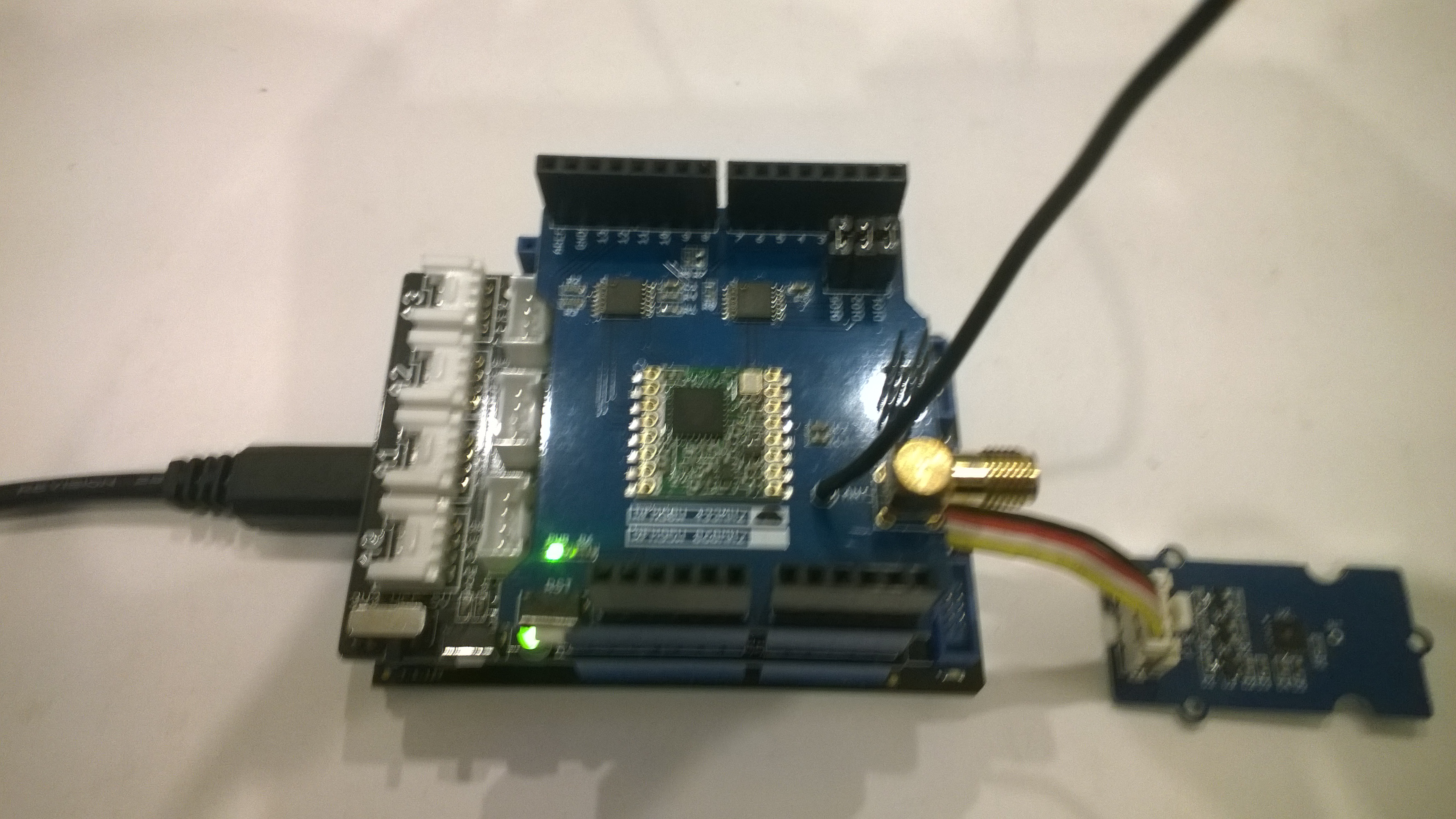
Dragino shield
MakerFabs shield
Net Micro Framework debug output from device
The thread '' (0x2) has exited with code 0 (0x0).
12:00:18 H:96.9 T:19.6
Transmit-Done
12:05:17 H:95.1 T:20.1
Transmit-Done
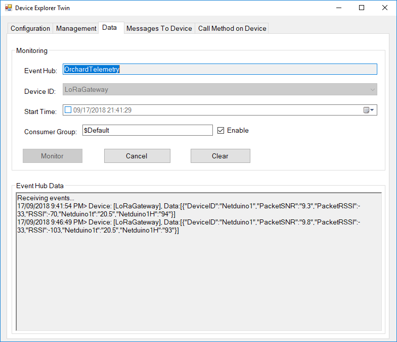
.Net Framework debug output Field Gateway
The thread 0x1550 has exited with code 0 (0x0).
21:21:49-RX From Netduino1 PacketSnr 9.5 Packet RSSI -40dBm RSSI -107dBm = 11 byte message "t 19.6,H 97"
 Sensor Netduino1t Value 19.6
 Sensor Netduino1H Value 97
 AzureIoTHubClient SendEventAsync start
 AzureIoTHubClient SendEventAsync finish
...
21:26:49-RX From Netduino1 PacketSnr 9.5 Packet RSSI -33dBm RSSI -103dBm = 11 byte message "t 20.1,H 95"
 Sensor Netduino1t Value 20.1
 Sensor Netduino1H Value 95
 AzureIoTHubClient SendEventAsync start
 AzureIoTHubClient SendEventAsync finish
The thread 0xfbc has exited with code 0 (0x0).