Random wanderings through Microsoft Azure esp. PaaS plumbing, the IoT bits, AI on Micro controllers, AI on Edge Devices, .NET nanoFramework, .NET Core on *nix and ML.NET+ONNX
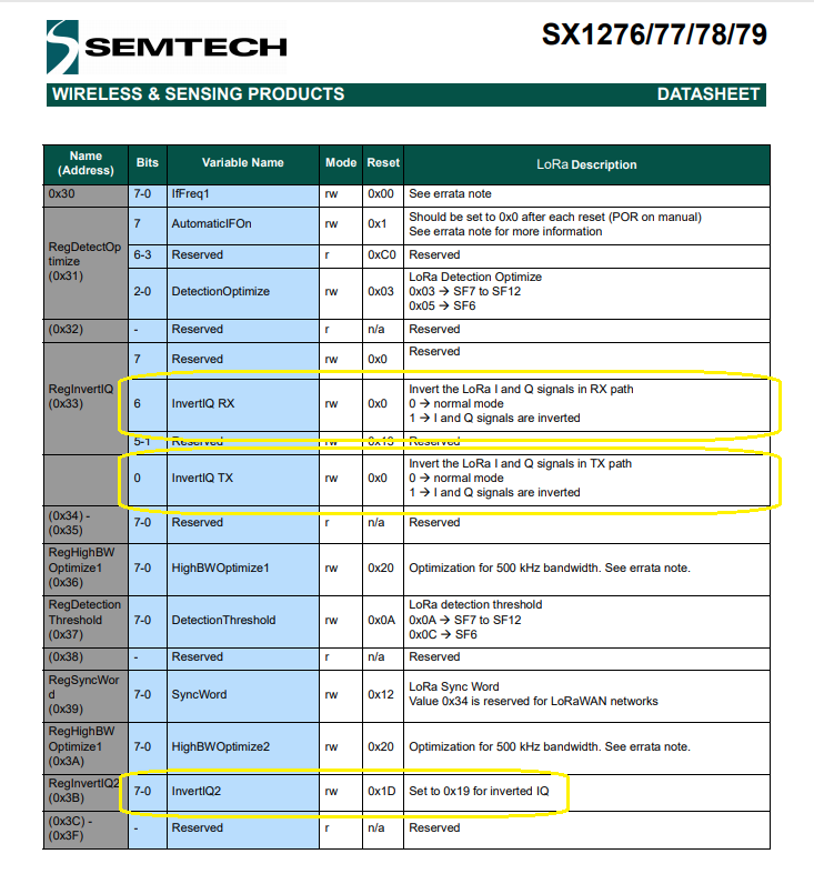
In RegInvertIQ the sixth bit is the RX flag and the zeroth bit is the TX flag, in the enable method the zeroth bit was not set(even number) and in the disable method it was set (odd number). The enable and disable method were “inverting” both the TX and RX lines.
When I did a RegisterDump the initial value of RegInvertIQ was 0x27 which is a bit odd as datasheet indicated the default value of the zeroth bit is 0.
My code supports the toggling of the RegInvertIQ “InvertIQ RX” and “InvertIQ TX” flags independently so users of the SX127X.NetCore library will need to pay attention to the configuration settings of the libraries used on other client devices.
	class Program
	{
		static void Main(string[] args)
		{
			int messageCount = 1;
			// Uptronics has no reset pin uses CS0 or CS1
			//SX127XDevice sX127XDevice = new SX127XDevice(25, chipSelectLine: 0);
			//SX127XDevice sX127XDevice = new SX127XDevice(25, chipSelectLine: 1);

			// M2M device has reset pin uses non standard chip select
			//SX127XDevice sX127XDevice = new SX127XDevice(4, chipSelectLine: 0, chipSelectLogicalPinNumber: 25, resetPin: 17);
			SX127XDevice sX127XDevice = new SX127XDevice(4, chipSelectLine: 1, chipSelectLogicalPinNumber: 25, resetPinNumber: 17);

			// Put device into LoRa + Sleep mode
			sX127XDevice.WriteByte(0x01, 0b10000000); // RegOpMode

			// Set the frequency to 915MHz
			byte[] frequencyBytes = { 0xE4, 0xC0, 0x00 }; // RegFrMsb, RegFrMid, RegFrLsb
			sX127XDevice.WriteBytes(0x06, frequencyBytes);

			sX127XDevice.WriteByte(0x0F, 0x0); // RegFifoRxBaseAddress

			// More power PA Boost
			sX127XDevice.WriteByte(0x09, 0b10000000); // RegPaConfig

			sX127XDevice.WriteByte(0x40, 0b00000000); // RegDioMapping1 0b00000000 DI0 RxReady & TxReady

			sX127XDevice.WriteByte(0x01, 0b10000101); // RegOpMode set LoRa & RxContinuous

			while (true)
			{
				sX127XDevice.WriteByte(0x0E, 0x0); // RegFifoTxBaseAddress

				// Set the Register Fifo address pointer
				sX127XDevice.WriteByte(0x0D, 0x0); // RegFifoAddrPtr

				string messageText = "Hello LoRa from .NET Core! " + messageCount.ToString();
				messageCount += 1;

				// load the message into the fifo
				byte[] messageBytes = UTF8Encoding.UTF8.GetBytes(messageText);
				sX127XDevice.WriteBytes(0x00, messageBytes); // RegFifoAddrPtr

				// Set the length of the message in the fifo
				sX127XDevice.WriteByte(0x22, (byte)messageBytes.Length); // RegPayloadLength

				sX127XDevice.WriteByte(0x40, 0b01000000); // RegDioMapping1 0b00000000 DI0 RxReady & TxReady

				sX127XDevice.WriteByte(0x01, 0b10000011); // RegOpMode

				Debug.WriteLine($"Sending {messageBytes.Length} bytes message {messageText}");

				Thread.Sleep(10000);
			}
		}
	}
For the SX127X to transmit and receive messages the device has to be put into sleep mode (RegOpMode), the frequency set to 915MHz(RegFrMsb, RegFrMid, RegFrLsb) and the receiver enabled(RxContinuous). In addition interrupts have to be enabled(RegDioMapping1) on message received(RxReady) and message sent(TxReady).
When running the applications sleeps the SX127X module(RegOpMode), writes the message payload to the buffer(RegFifoAddrPtr,RegPayloadLength) then turns on the transmitter(RegOpMode). When has message arrived or a message has been sent the DI0 pin is strobed, the type of interrupt is determined (RegIrqFlags) and processed accordingly. Once the interrupt has been processed the interrupt flags(RegIrqFlags) are cleared, the receiver re-enabled and the interrupt mappings reset(RegDioMapping1) reset.
Loaded '/usr/lib/dotnet/shared/Microsoft.NETCore.App/5.0.4/System.Memory.dll'. Skipped loading symbols. Module is optimized and the debugger option 'Just My Code' is enabled.
Sending 28 bytes message Hello LoRa from .NET Core! 1
RegIrqFlags 00001000
Transmit-Done
RegIrqFlags 01010000
Receive-Message
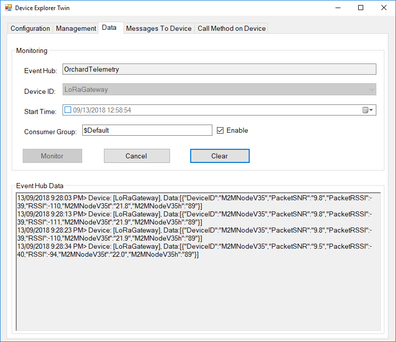
Received 32 byte message HeLoRa World! I'm a Node! 880000
Sending 28 bytes message Hello LoRa from .NET Core! 2
RegIrqFlags 00001000
Transmit-Done
RegIrqFlags 01010000
Receive-Message
Received 32 byte message HeLoRa World! I'm a Node! 890000
Sending 28 bytes message Hello LoRa from .NET Core! 3
RegIrqFlags 00001000
Transmit-Done
RegIrqFlags 01010000
Receive-Message
Received 32 byte message HeLoRa World! I'm a Node! 900000
Sending 28 bytes message Hello LoRa from .NET Core! 4
RegIrqFlags 00001000
Transmit-Done
RegIrqFlags 01010000
Receive-Message
Received 32 byte message HeLoRa World! I'm a Node! 910000
Sending 28 bytes message Hello LoRa from .NET Core! 5
RegIrqFlags 00001000
Transmit-Done
RegIrqFlags 01010000
Receive-Message
Received 32 byte message HeLoRa World! I'm a Node! 920000
class Program
{
	static void Main(string[] args)
	{
		// M2M device has reset pin uses non standard chip select
		SX127XDevice sX127XDevice = new SX127XDevice(chipSelectLine: 1, chipSelectLogicalPinNumber: 25, resetPin: 17);

		// Put device into LoRa + Sleep mode
		sX127XDevice.WriteByte(0x01, 0b10000000); // RegOpMode

		// Set the frequency to 915MHz
		byte[] frequencyBytes = { 0xE4, 0xC0, 0x00 }; // RegFrMsb, RegFrMid, RegFrLsb
		sX127XDevice.WriteBytes(0x06, frequencyBytes);

		sX127XDevice.WriteByte(0x0F, 0x0); // RegFifoRxBaseAddress

		sX127XDevice.WriteByte(0x01, 0b10000101); // RegOpMode set LoRa & RxContinuous

		while (true)
		{
			// Wait until a packet is received, no timeouts in PoC
			Console.WriteLine("Receive-Wait");
			byte IrqFlags = sX127XDevice.ReadByte(0x12); // RegIrqFlags
			while ((IrqFlags & 0b01000000) == 0)  // wait until RxDone cleared
			{
				Thread.Sleep(100);
				IrqFlags = sX127XDevice.ReadByte(0x12); // RegIrqFlags
				Debug.Write(".");
			}
			Console.WriteLine("");
			Console.WriteLine($"RegIrqFlags {Convert.ToString((byte)IrqFlags, 2).PadLeft(8, '0')}");
			Console.WriteLine("Receive-Message");
			byte currentFifoAddress = sX127XDevice.ReadByte(0x10); // RegFifiRxCurrent
			sX127XDevice.WriteByte(0x0d, currentFifoAddress); // RegFifoAddrPtr

			byte numberOfBytes = sX127XDevice.ReadByte(0x13); // RegRxNbBytes

			// Read the message from the FIFO
			byte[] messageBytes = sX127XDevice.ReadBytes(0x00, numberOfBytes);

			sX127XDevice.WriteByte(0x0d, 0);
			sX127XDevice.WriteByte(0x12, 0b11111111); // RegIrqFlags clear all the bits

			string messageText = UTF8Encoding.UTF8.GetString(messageBytes);
			Console.WriteLine($"Received {messageBytes.Length} byte message {messageText}");

			Console.WriteLine("Receive-Done");
		}
	}
}
There wasn’t much code to configure the SX127X to receive messages. The device has to be put into sleep mode (RegOpMode), the frequency set to 915MHz(RegFrMsb, RegFrMid, RegFrLsb) and receiver enabled(RxContinuous).
While running the applications polls (RegIrqFlags) until a message has arrived (RxDone). It then gets a pointer to the start of the message buffer (RegFifiRxCurrent, RegFifoAddrPtr), gets the message length, and then reads the message (RegPayloadLength, RegFifo) from the buffer. Finally the flags are reset ready for the next message(RegIrqFlags)
Loaded '/usr/lib/dotnet/shared/Microsoft.NETCore.App/5.0.4/System.Memory.dll'. Skipped loading symbols. Module is optimized and the debugger option 'Just My Code' is enabled.
Sending 28 bytes message Hello LoRa from .NET Core! 1
RegIrqFlags 00001000
Transmit-Done
RegIrqFlags 01010000
Receive-Message
Received 31 byte message HeLoRa World! I'm a Node! 20000
Sending 28 bytes message Hello LoRa from .NET Core! 2
RegIrqFlags 00001000
Transmit-Done
RegIrqFlags 01010000
Receive-Message
Received 31 byte message HeLoRa World! I'm a Node! 30000
Sending 28 bytes message Hello LoRa from .NET Core! 3
RegIrqFlags 00001000
Transmit-Done
RegIrqFlags 01010000
Receive-Message
Received 31 byte message HeLoRa World! I'm a Node! 40000
Sending 28 bytes message Hello LoRa from .NET Core! 4
RegIrqFlags 00001000
Transmit-Done
RegIrqFlags 01010000
Receive-Message
Received 31 byte message HeLoRa World! I'm a Node! 50000
Sending 28 bytes message Hello LoRa from .NET Core! 5
RegIrqFlags 00001000
Transmit-Done
RegIrqFlags 01010000
Receive-Message
Received 31 byte message HeLoRa World! I'm a Node! 60000
Sending 28 bytes message Hello LoRa from .NET Core! 6
RegIrqFlags 00001000
Transmit-Done
RegIrqFlags 01010000
Receive-Message
Received 31 byte message HeLoRa World! I'm a Node! 70000
Sending 28 bytes message Hello LoRa from .NET Core! 7
RegIrqFlags 00001000
Transmit-Done
RegIrqFlags 01010000
Receive-Message
Received 31 byte message HeLoRa World! I'm a Node! 80000
Sending 28 bytes message Hello LoRa from .NET Core! 8
RegIrqFlags 00001000
Transmit-Done
My first attempt didn’t have much range so I tried turning on the PA_BOOST pin (in RegPaConfig) which improved the range and Received Signal Strength Indication (RSSI).
Arduino Monitor displaying received messages
There was quite a bit of code to configure the SX127X to Transmit messages. I had to put the device into sleep mode (RegOpMode), set the frequency to 915MHz(RegFrMsb, RegFrMid, RegFrLsb), and set the output power(RegPaConfig). Then for each message reset the pointer to the start of the message buffer(RegFifoTxBaseAddress, RegFifoAddrPtr), load the message into the buffer (RegPayloadLength), then turn on the transmitter(RegOpMode), and then finally poll (RegIrqFlags) until the message was sent(TxDone).
class Program
{
	static void Main(string[] args)
	{
		Byte regOpMode;
		ushort preamble;
		byte[] frequencyBytes;

		// M2M device has reset pin uses non standard chip select
		SX127XDevice sX127XDevice = new SX127XDevice(chipSelectLine: 1, chipSelectLogicalPinNumber: 25, resetPin: 17);

		// Put device into LoRa + Sleep mode
		sX127XDevice.WriteByte(0x01, 0b10000000); // RegOpMode

		// Set the frequency to 915MHz
		byte[] frequencyWriteBytes = { 0xE4, 0xC0, 0x00 }; // RegFrMsb, RegFrMid, RegFrLsb
		sX127XDevice.WriteBytes(0x06, frequencyWriteBytes);

		// More power PA Boost
		sX127XDevice.WriteByte(0x09, 0b10000000); // RegPaConfig

		while (true)
		{
			sX127XDevice.WriteByte(0x0E, 0x0); // RegFifoTxBaseAddress

			// Set the Register Fifo address pointer
			sX127XDevice.WriteByte(0x0D, 0x0); // RegFifoAddrPtr

			string messageText = "Hello LoRa from .NET Core!";

			// load the message into the fifo
			byte[] messageBytes = UTF8Encoding.UTF8.GetBytes(messageText);
			foreach (byte b in messageBytes)
			{
				sX127XDevice.WriteByte(0x0, b); // RegFifo
			}

			// Set the length of the message in the fifo
			sX127XDevice.WriteByte(0x22, (byte)messageBytes.Length); // RegPayloadLength

			Debug.WriteLine($"Sending {messageBytes.Length} bytes message \"{messageText}\"");
			/// Set the mode to LoRa + Transmit
			sX127XDevice.WriteByte(0x01, 0b10000011); // RegOpMode

			// Wait until send done, no timeouts in PoC
			Debug.WriteLine("Send-wait");
			byte IrqFlags = sX127XDevice.ReadByte(0x12); // RegIrqFlags
			while ((IrqFlags & 0b00001000) == 0)  // wait until TxDone cleared
			{
				Thread.Sleep(10);
				IrqFlags = sX127XDevice.ReadByte(0x12); // RegIrqFlags
				Debug.Write(".");
			}
			Debug.WriteLine("");
			sX127XDevice.WriteByte(0x12, 0b00001000); // clear TxDone bit
			Debug.WriteLine("Send-Done");

			Thread.Sleep(30000);
		}
	}
}
Loaded '/usr/lib/dotnet/shared/Microsoft.NETCore.App/5.0.4/System.Memory.dll'. Skipped loading symbols. Module is optimized and the debugger option 'Just My Code' is enabled.
Sending 26 bytes message "Hello LoRa from .NET Core!"
Send-wait
....
Send-Done
Sending 26 bytes message "Hello LoRa from .NET Core!"
Send-wait
...
Send-Done
Sending 26 bytes message "Hello LoRa from .NET Core!"
Send-wait
...
Send-Done
Sending 26 bytes message "Hello LoRa from .NET Core!"
Send-wait
...
Send-Done
Sending 26 bytes message "Hello LoRa from .NET Core!"
Send-wait
...
Send-Done
Sending 26 bytes message "Hello LoRa from .NET Core!"
Send-wait
...
Send-Done
Sending 26 bytes message "Hello LoRa from .NET Core!"
Send-wait
...
Send-Done
static void Main(string[] args)
{
	Byte regOpMode;
	ushort preamble;
	byte[] frequencyBytes;
	// Uptronics has no reset pin uses CS0 or CS1
	//SX127XDevice sX127XDevice = new SX127XDevice(chipSelectLine: 0);
	//SX127XDevice sX127XDevice = new SX127XDevice(chipSelectLine: 1);

	// M2M device has reset pin uses non standard chip select
	//SX127XDevice sX127XDevice = new SX127XDevice(chipSelectLine: 0, chipSelectLogicalPinNumber: 25, resetPin: 17);
	SX127XDevice sX127XDevice = new SX127XDevice(chipSelectLine: 1, chipSelectLogicalPinNumber:25, resetPin: 17);

	Console.WriteLine("In FSK mode");
	sX127XDevice.RegisterDump();


	Console.WriteLine("Read RegOpMode (read byte)");
	regOpMode = sX127XDevice.ReadByte(0x1);
	Debug.WriteLine($"RegOpMode 0x{regOpMode:x2}");

	Console.WriteLine("Set LoRa mode and sleep mode (write byte)");
	sX127XDevice.WriteByte(0x01, 0b10000000);

	Console.WriteLine("Read RegOpMode (read byte)");
	regOpMode = sX127XDevice.ReadByte(0x1);
	Debug.WriteLine($"RegOpMode 0x{regOpMode:x2}");


	Console.WriteLine("In LoRa mode");
	sX127XDevice.RegisterDump();


	Console.WriteLine("Read the preamble (read word)"); // Should be 0x08
	preamble = sX127XDevice.ReadWordMsbLsb(0x20);
	Debug.WriteLine($"Preamble 0x{preamble:x2} - Bits {Convert.ToString(preamble, 2).PadLeft(16, '0')}");

	Console.WriteLine("Set the preamble to 0x8000 (write word)");
	sX127XDevice.WriteWordMsbLsb(0x20, 0x8000);

	Console.WriteLine("Read the preamble (read word)"); // Should be 0x08
	preamble = sX127XDevice.ReadWordMsbLsb(0x20);
	Debug.WriteLine($"Preamble 0x{preamble:x2} - Bits {Convert.ToString(preamble, 2).PadLeft(16, '0')}");


	Console.WriteLine("Read the centre frequency"); // RegFrfMsb 0x6c RegFrfMid 0x80 RegFrfLsb 0x00 which is 433MHz
	frequencyBytes = sX127XDevice.ReadBytes(0x06, 3);
	Console.WriteLine($"Frequency Msb 0x{frequencyBytes[0]:x2} Mid 0x{frequencyBytes[1]:x2} Lsb 0x{frequencyBytes[2]:x2}");

	Console.WriteLine("Set the centre frequency");
	byte[] frequencyWriteBytes = { 0xE4, 0xC0, 0x00 };
	sX127XDevice.WriteBytes(0x06, frequencyWriteBytes);

	Console.WriteLine("Read the centre frequency"); // RegFrfMsb 0xE4 RegFrfMid 0xC0 RegFrfLsb 0x00 which is 915MHz
	frequencyBytes = sX127XDevice.ReadBytes(0x06, 3);
	Console.WriteLine($"Frequency Msb 0x{frequencyBytes[0]:x2} Mid 0x{frequencyBytes[1]:x2} Lsb 0x{frequencyBytes[2]:x2}");


	sX127XDevice.RegisterDump();

	// Sleep forever
	Thread.Sleep(-1);
}
I use RegisterDump multiple times to show the updates working.
...
Loaded '/usr/lib/dotnet/shared/Microsoft.NETCore.App/5.0.4/Microsoft.Win32.Primitives.dll'. Skipped loading symbols. Module is optimized and the debugger option 'Just My Code' is enabled.
In FSK mode
Register dump
Register 0x00 - Value 0X00 - Bits 00000000
Register 0x01 - Value 0X09 - Bits 00001001
Register 0x02 - Value 0X1a - Bits 00011010
Register 0x03 - Value 0X0b - Bits 00001011
Register 0x04 - Value 0X00 - Bits 00000000
Register 0x05 - Value 0X52 - Bits 01010010
Register 0x06 - Value 0X6c - Bits 01101100
Register 0x07 - Value 0X80 - Bits 10000000
...
Register 0x1f - Value 0X40 - Bits 01000000
Register 0x20 - Value 0X00 - Bits 00000000
Register 0x21 - Value 0X00 - Bits 00000000
Register 0x22 - Value 0X00 - Bits 00000000
...
Register 0x41 - Value 0X00 - Bits 00000000
Register 0x42 - Value 0X12 - Bits 00010010

Read RegOpMode (read byte)
RegOpMode 0x09
Set LoRa mode and sleep mode (write byte)
Read RegOpMode (read byte)
RegOpMode 0x80
In LoRa mode
Register dump
Register 0x00 - Value 0Xdf - Bits 11011111
Register 0x01 - Value 0X80 - Bits 10000000
Register 0x02 - Value 0X1a - Bits 00011010
Register 0x03 - Value 0X0b - Bits 00001011
Register 0x04 - Value 0X00 - Bits 00000000
Register 0x05 - Value 0X52 - Bits 01010010
Register 0x06 - Value 0X6c - Bits 01101100
Register 0x07 - Value 0X80 - Bits 10000000
...
Register 0x1f - Value 0X64 - Bits 01100100
Register 0x20 - Value 0X00 - Bits 00000000
Register 0x21 - Value 0X08 - Bits 00001000
Register 0x22 - Value 0X01 - Bits 00000001
...
Register 0x41 - Value 0X00 - Bits 00000000
Register 0x42 - Value 0X12 - Bits 00010010

Read the preamble (read word)
Preamble 0x08 - Bits 0000000000001000
Set the preamble to 0x8000 (write word)
Read the preamble (read word)
Preamble 0x8000 - Bits 1000000000000000
Read the centre frequency
Frequency Msb 0x6c Mid 0x80 Lsb 0x00
Set the centre frequency
Read the centre frequency
Frequency Msb 0xe4 Mid 0xc0 Lsb 0x00
Register dump
Register 0x00 - Value 0Xb9 - Bits 10111001
Register 0x01 - Value 0X80 - Bits 10000000
Register 0x02 - Value 0X1a - Bits 00011010
Register 0x03 - Value 0X0b - Bits 00001011
Register 0x04 - Value 0X00 - Bits 00000000
Register 0x05 - Value 0X52 - Bits 01010010
Register 0x06 - Value 0Xe4 - Bits 11100100
Register 0x07 - Value 0Xc0 - Bits 11000000
...
Register 0x1f - Value 0X64 - Bits 01100100
Register 0x20 - Value 0X80 - Bits 10000000
Register 0x21 - Value 0X00 - Bits 00000000
Register 0x22 - Value 0X01 - Bits 00000001
...
Register 0x3f - Value 0X00 - Bits 00000000
Register 0x40 - Value 0X00 - Bits 00000000
Summary
In this iteration I added support for resetting the SX127X module (where supported by the Raspberry PI HAT) and an spiDevice.TransferFullDuplex based implementation for reading/writing individual bytes/words and reading/writing arrays of bytes.
public byte[] ReadBytes(byte registerAddress, byte length)
{
	Span<byte> writeBuffer = stackalloc byte[length + 1];
	Span<byte> readBuffer = stackalloc byte[writeBuffer.Length];

	if (SX127XTransceiver == null)
	{
		throw new ApplicationException("SX127XDevice is not initialised");
	}

	writeBuffer[0] = registerAddress &= RegisterAddressReadMask;

	if (this.ChipSelectLogicalPinNumber != 0)
	{
		gpioController.Write(ChipSelectLogicalPinNumber, PinValue.Low);
	}

	this.SX127XTransceiver.TransferFullDuplex(writeBuffer, readBuffer);

	if (this.ChipSelectLogicalPinNumber != 0)
	{
		gpioController.Write(ChipSelectLogicalPinNumber, PinValue.High);
	}

	return readBuffer[1..readBuffer.Length].ToArray();
}
public void WriteBytes(byte address, byte[] bytes)
{
	Span<byte> writeBuffer = stackalloc byte[bytes.Length + 1];
	Span<byte> readBuffer = stackalloc byte[writeBuffer.Length];

	if (SX127XTransceiver == null)
	{
		throw new ApplicationException("SX127XDevice is not initialised");
	}

	writeBuffer[0] = address |= RegisterAddressWriteMask;
	for (byte index = 0; index < bytes.Length; index++)
	{
		writeBuffer[index + 1] = bytes[index];
	}

	if (this.ChipSelectLogicalPinNumber != 0)
	{
		gpioController.Write(ChipSelectLogicalPinNumber, PinValue.Low);
	}

	this.SX127XTransceiver.TransferFullDuplex(writeBuffer, readBuffer);

	if (this.ChipSelectLogicalPinNumber != 0)
	{
		gpioController.Write(ChipSelectLogicalPinNumber, PinValue.High);
	}
}
In the WriteBytes method copying the bytes from the bytes[] parameter to the span with a for loop is a bit ugly but I couldn’t find a better way. One odd thing I noticed was that if I wrote a lot of debug output the text would be truncated in the output window
Frequency Msb 0xe4 Mid 0xc0 Lsb 0x00
Register dump
Register 0x00 - Value 0Xb9 - Bits 10111001
Register 0x01 - Value 0X80 - Bits 10000000
Register 0x02 - Value 0X1a - Bits 00011010
Register 0x03 - Value 0X0b - Bits 00001011
Register 0x04 - Value 0X00 - Bits 00000000
Register 0x05 - Value 0X52 - Bits 01010010
Register 0x06 - Value 0Xe4 - Bits 11100100
Register 0x07 - Value 0Xc0 - Bits 11000000
Register 0x08 - Value 0X00 - Bits 00000000
Register 0x09 - Value 0X4f - Bits 01001111
Register 0x0a - Value 0X09 - Bits 00001001
Register 0x0b - Value 0X2b - Bits 00101011
Register 0x0c - Value 0X20 - Bits 00100000
Register 0x0d - Value 0X02 - Bits 00000010
Register 0x0e - Value 0X80 - Bits 10000000
Register 0x0f - Value 0X00 - Bits 00000000
Register 0x10 - Value 0X00 - Bits 00000000
Register 0x11 - Value 0X00 - Bits 00000000
Register 0x12 - Value 0X00 - Bits 00000000
Register 0x13 - Value 0X00 - Bits 00000000
Register 0x14 - Value 0X00 - Bits 00000000
Register 0x15 - Value 0X00 - Bits 00000000
Register 0x16 - Value 0X00 - Bits 00000000
Register 0x17 - Value 0X00 - Bits 00000000
Register 0x18 - Value 0X10 - Bits 00010000
Register 0x19 - Value 0X00 - Bits 00000000
Register 0x1a - Value 0X00 - Bits 00000000
Register 0x1b - Value 0X00 - Bits 00000000
Register 0x1c - Value 0X00 - Bits 00000000
Register 0x1d - Value 0X72 - Bits 01110010
Register 0x1e - Value 0X70 - Bits 01110000
Register 0x1f - Value 0X64 - Bits 01100100
Register 0x20 - Value 0X80 - Bits 10000000
Register 0x21 - Value 0X00 - Bits 00000000
Register 0x22 - Value 0X01 - Bits 00000001
Register 0x23 - Value 0Xff - Bits 11111111
Register 0x24 - Value 0X00 - Bits 00000000
Register 0x25 - Value 0X00 - Bits 00000000
Register 0x26 - Value 0X04 - Bits 00000100
Register 0x27 - Value 0X00 - Bits 00000000
Register 0x28 - Value 0X00 - Bits 00000000
Register 0x29 - Value 0X00 - Bits 00000000
Register 0x2a - Value 0X00 - Bits 00000000
Register 0x2b - Value 0X00 - Bits 00000000
Register 0x2c - Value 0X00 - Bits 00000000
Register 0x2d - Value 0X50 - Bits 01010000
Register 0x2e - Value 0X14 - Bits 00010100
Register 0x2f - Value 0X45 - Bits 01000101
Register 0x30 - Value 0X55 - Bits 01010101
Register 0x31 - Value 0Xc3 - Bits 11000011
Register 0x32 - Value 0X05 - Bits 00000101
Register 0x33 - Value 0X27 - Bits 00100111
Register 0x34 - Value 0X1c - Bits 00011100
Register 0x35 - Value 0X0a - Bits 00001010
Register 0x36 - Value 0X03 - Bits 00000011
Register 0x37 - Value 0X0a - Bits 00001010
Register 0x38 - Value 0X42 - Bits 01000010
Register 0x39 - Value 0X12 - Bits 00010010
Register 0x3a - Value 0X49 - Bits 01001001
Register 0x3b - Value 0X1d - Bits 00011101
Register 0x3c - Value 0X00 - Bits 00000000
Register 0x3d - Value 0Xaf - Bits 10101111
Register 0x3e - Value 0X00 - Bits 00000000
Register 0x3f - Value 0X00 - Bits 00000000
Register 0x40 - Value 0X00 - Bits 00000000
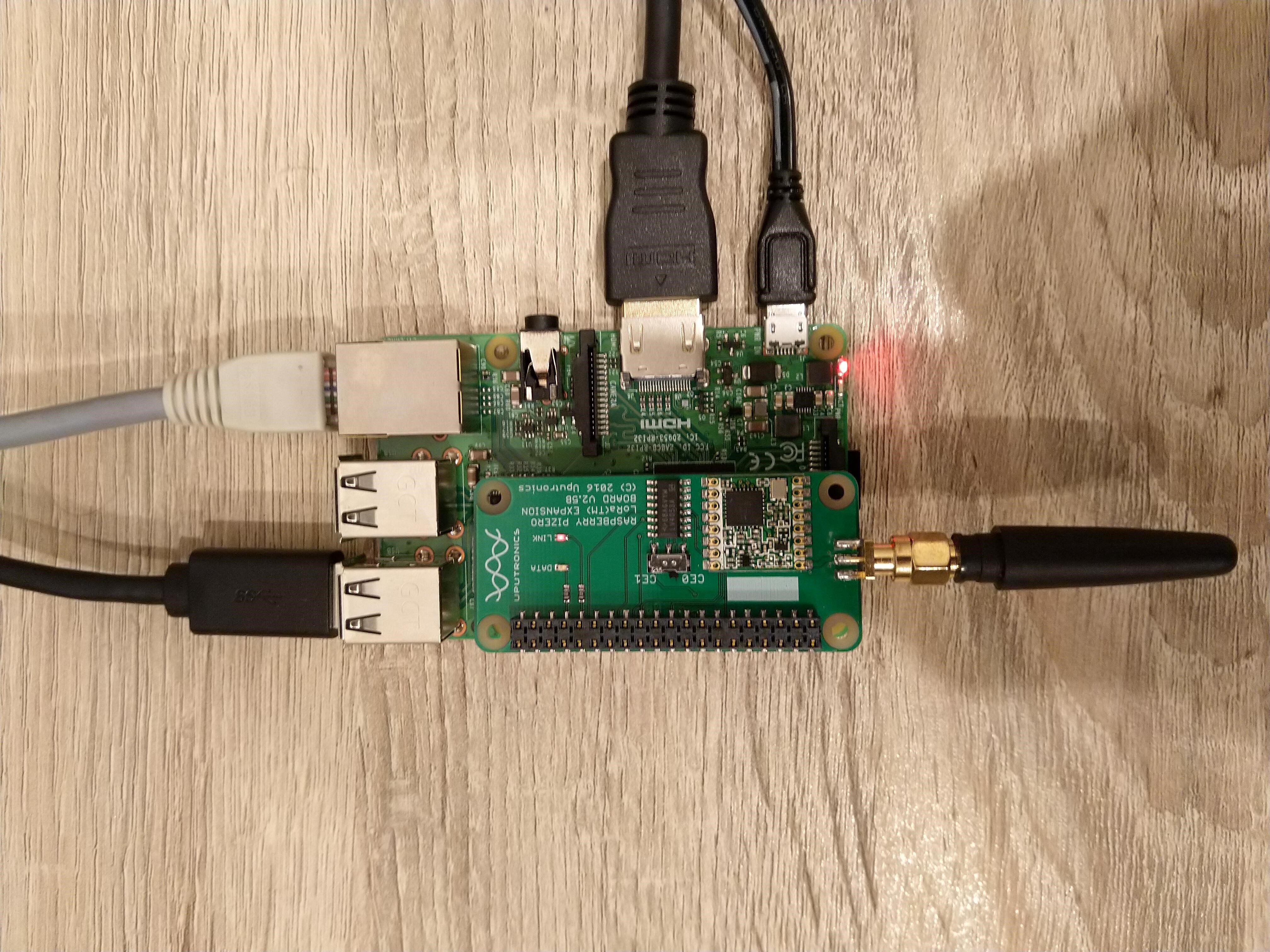
Uputronics Raspberry PIZero LoRa Expansion board on a Raspberry PI 3 device
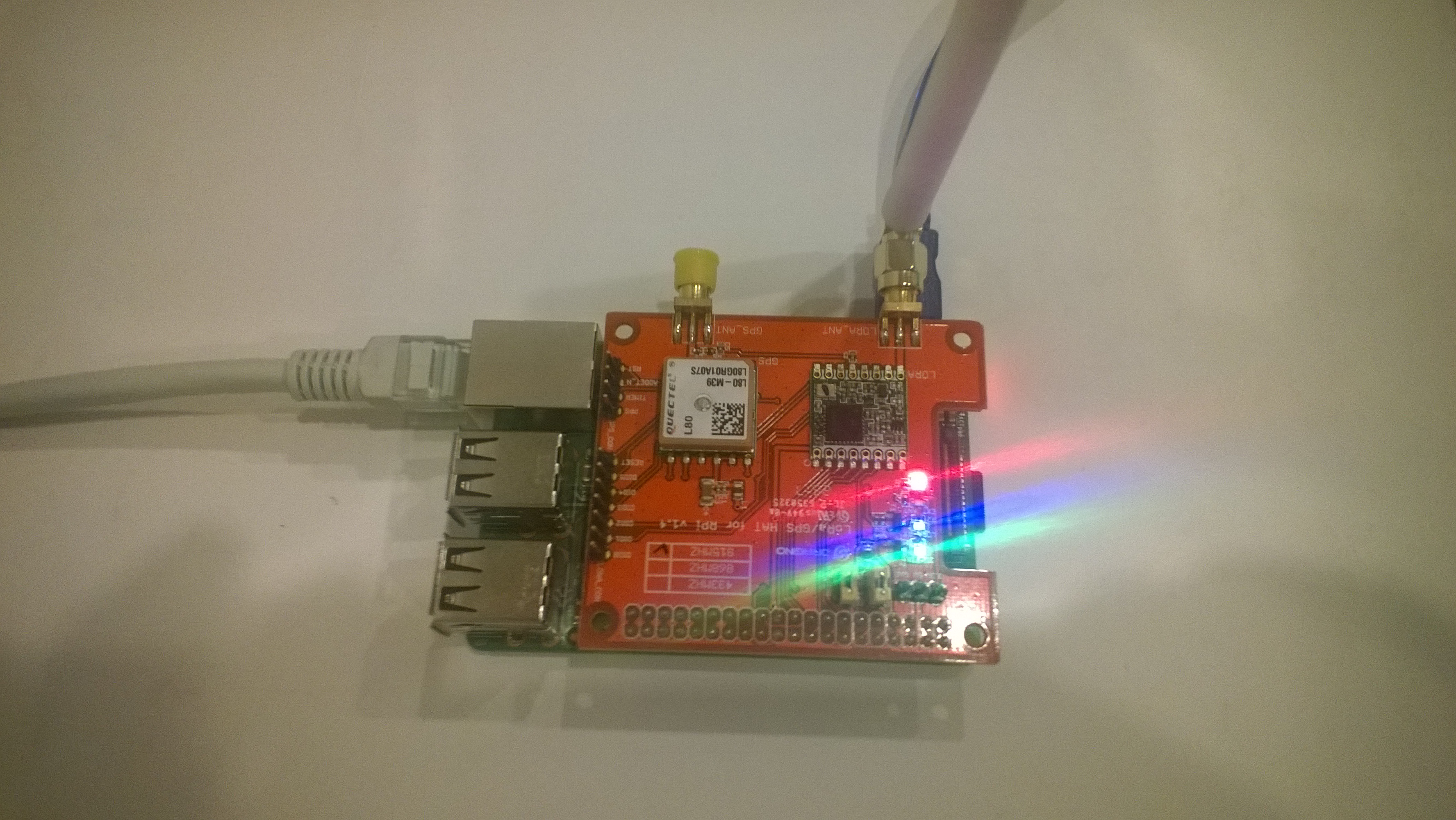
M2M Single channel shield on Raspberry Pi 3 Device
The spiDevice.ReadByte() and spiDevice.WriteBye() version worked with a custom chip select pin(25) and CS0 or CS1 selected in the SpiConnectionSettings (but this CS line was “unusable” by other applications). This approach also worked with standard select line (CS01 or CS1) if the SpiConnectionSettings was configured to use the “other” CS line and the selected CS pin managed by the application.
namespace devMobile.IoT.SX127x.ShieldSPIWriteRead
{
	class Program
	{
		private const int SpiBusId = 0;
		private const int ChipSelectLine = 1; // 0 or 1 for Uputronics depends on the switch, for the others choose CS pin not already in use
#if ChipSelectNonStandard
		private const int ChipSelectPinNumber = 25; // 25 for M2M, Dragino etc.
#endif
		private const byte RegisterAddress = 0x6; // RegFrfMsb 0x6c
		//private const byte RegisterAddress = 0x7; // RegFrfMid 0x80
		//private const byte RegisterAddress = 0x8; // RegFrfLsb 0x00
		//private const byte RegisterAddress = 0x42; // RegVersion 0x12

		static void Main(string[] args)
		{
#if ChipSelectNonStandard
			GpioController controller = null;

			controller = new GpioController(PinNumberingScheme.Logical);

			controller.OpenPin(ChipSelectPinNumber, PinMode.Output);
			controller.Write(ChipSelectPinNumber, PinValue.High);
#endif

			var settings = new SpiConnectionSettings(SpiBusId, ChipSelectLine)
			{
				ClockFrequency = 5000000,
				Mode = SpiMode.Mode0,   // From SemTech docs pg 80 CPOL=0, CPHA=0
			};

			SpiDevice spiDevice = SpiDevice.Create(settings);

			Thread.Sleep(500);

			while (true)
			{
#if ChipSelectNonStandard
				controller.Write(ChipSelectPinNumber, PinValue.Low);
#endif

				spiDevice.WriteByte(RegisterAddress);
				byte registerValue = spiDevice.ReadByte();

#if ChipSelectNonStandard
				controller.Write(ChipSelectPinNumber, PinValue.High);
#endif

				byte registerValue = readBuffer[writeBuffer.Length - 1];

				Console.WriteLine($"Register 0x{RegisterAddress:x2} - Value 0X{registerValue:x2} - Bits {Convert.ToString(registerValue, 2).PadLeft(8, '0')}");

				Thread.Sleep(5000);
			}
		}
	}
}
The spiDevice.TransferFullDuplex worked for a standard CS line (CS0 or CS1), and for a non-standard CS line, though the CS line configured in SpiConnectionSettings was “unusable” by other applications “.
namespace devMobile.IoT.SX127x.ShieldSPITransferFullDuplex
{
	class Program
	{
		private const int SpiBusId = 0;
		private const int ChipSelectLine = 0; // 0 or 1 for Uputronics depends on the switch, for the others choose CS pin not already in use
#if ChipSelectNonStandard
		private const int ChipSelectPinNumber = 25; // 25 for M2M, Dragino etc.
#endif
		private const byte RegisterAddress = 0x6; // RegFrfMsb 0x6c
		//private const byte RegisterAddress = 0x7; // RegFrfMid 0x80
		//private const byte RegisterAddress = 0x8; // RegFrfLsb 0x00
		//private const byte RegisterAddress = 0x42; // RegVersion 0x12

		static void Main(string[] args)
		{
#if ChipSelectNonStandard
			GpioController controller = null;

			controller = new GpioController(PinNumberingScheme.Logical);

			controller.OpenPin(ChipSelectPinNumber, PinMode.Output);
			controller.Write(ChipSelectPinNumber, PinValue.High);
#endif

			var settings = new SpiConnectionSettings(SpiBusId, ChipSelectLine)
			{
				ClockFrequency = 5000000,
				Mode = SpiMode.Mode0,   // From SemTech docs pg 80 CPOL=0, CPHA=0
			};

			SpiDevice spiDevice = SpiDevice.Create(settings);

			Thread.Sleep(500);

			while (true)
			{
				byte[] writeBuffer = new byte[] { RegisterAddress, 0 };
				byte[] readBuffer = new byte[writeBuffer.Length];

#if ChipSelectNonStandard
				controller.Write(ChipSelectPinNumber, PinValue.Low);
#endif

				spiDevice.TransferFullDuplex(writeBuffer, readBuffer);

#if ChipSelectNonStandard
				controller.Write(ChipSelectPinNumber, PinValue.High);
#endif

				byte registerValue = readBuffer[writeBuffer.Length - 1];

				Console.WriteLine($"Register 0x{RegisterAddress:x2} - Value 0X{registerValue:x2} - Bits {Convert.ToString(registerValue, 2).PadLeft(8, '0')}");

				Thread.Sleep(5000);
			}
		}
	}
}
The output when the application was working as expected
Loaded '/usr/lib/dotnet/shared/Microsoft.NETCore.App/5.0.4/Microsoft.Win32.Primitives.dll'. Skipped loading symbols. Module is optimized and the debugger option 'Just My Code' is enabled.
Register 0x06 - Value 0X6c - Bits 01101100
Register 0x06 - Value 0X6c - Bits 01101100
Register 0x06 - Value 0X6c - Bits 01101100
Register 0x06 - Value 0X6c - Bits 01101100
Register 0x06 - Value 0X6c - Bits 01101100
Register 0x06 - Value 0X6c - Bits 01101100
The program 'dotnet' has exited with code 0 (0x0).
Summary
Though the spiDevice.TransferFullDuplex code was slightly more complex it worked with both standard and non-standard CS pins.
Uputronics Raspberry PIZero LoRa Expansion board on a Raspberry 3 device
The Uputronics pHat has a pair of Light Emitting Diodes(LEDs) so I adapted some code from a previous post to flash these to confirm the card was working.
static void UputronicsLeds()
{
	const int RedLedPinNumber = 6;
	const int GreenLedPinNumber = 13;

	GpioController controller = new GpioController(PinNumberingScheme.Logical);

	controller.OpenPin(RedLedPinNumber, PinMode.Output);
	controller.OpenPin(GreenLedPinNumber, PinMode.Output);

	while (true)
	{
		if (controller.Read(RedLedPinNumber) == PinValue.Low)
		{
			controller.Write(RedLedPinNumber, PinValue.High);
			controller.Write(GreenLedPinNumber, PinValue.Low);
		}
		else
		{
			controller.Write(RedLedPinNumber, PinValue.Low);
			controller.Write(GreenLedPinNumber, PinValue.High);
		}

		Thread.Sleep(1000);
	}
}
The first Uputronics pHat version using spiDevice.TransferFullDuplex didn’t work. I tried allocating memory for the buffers with new and stackalloc which didn’t seem to make any difference in my trivial example. I tried different Chip Select(CS) pin options, frequencies and modes (the mode used is based on the timings specified in the SX127X datasheet).
static void TransferFullDuplex()
{
	//byte[] writeBuffer = new byte[1]; // Memory allocation didn't seem to make any difference
    //byte[] readBuffer = new byte[1];
	Span<byte> writeBuffer = stackalloc byte[1];
	Span<byte> readBuffer = stackalloc byte[1];

	//var settings = new SpiConnectionSettings(0)
	var settings = new SpiConnectionSettings(0, 0)
	//var settings = new SpiConnectionSettings(0, 1)
	{
		ClockFrequency = 5000000,
		//ClockFrequency = 500000, // Frequency didn't seem to make any difference
		Mode = SpiMode.Mode0,   // From SemTech docs pg 80 CPOL=0, CPHA=0
	};

	SpiDevice spiDevice = SpiDevice.Create(settings);

	Thread.Sleep(500);

	while (true)
	{
		try
		{
			for (byte registerIndex = 0; registerIndex <= 0x42; registerIndex++)
			{
				writeBuffer[0] = registerIndex;
				spiDevice.TransferFullDuplex(writeBuffer, readBuffer);
				//Debug.WriteLine("Register 0x{0:x2} - Value 0X{1:x2} - Bits {2}", writeBuffer[0], readBuffer[0], Convert.ToString(readBuffer[0], 2).PadLeft(8, '0')); // Debug output stopped after roughly 3 times round for loop often debugger would barf as well
				Console.WriteLine("Register 0x{0:x2} - Value 0X{1:x2} - Bits {2}", writeBuffer[0], readBuffer[0], Convert.ToString(readBuffer[0], 2).PadLeft(8, '0'));

				// Would be nice if SpiDevice has a TransferSequential
				/*
				writeBuffer[0] = registerIndex;
				spiDevice.TransferSequential(writeBuffer, readBuffer);
				Console.WriteLine("Register 0x{0:x2} - Value 0X{1:x2} - Bits {2}", writeBuffer[0], readBuffer[0], Convert.ToString(readBuffer[0], 2).PadLeft(8, '0'));
				*/
			}

			Console.WriteLine("");
			Thread.Sleep(5000);
		}
		catch (Exception ex)
		{
			Console.WriteLine(ex.Message);
		}
	}
}
static void ReadWriteChipSelectStandard()
{
	var settings = new SpiConnectionSettings(0) // Doesn't work
	//	var settings = new SpiConnectionSettings(0, 0) // Doesn't work
	//var settings = new SpiConnectionSettings(0, 1) // Doesn't Work
	{
		ClockFrequency = 5000000,
		ChipSelectLineActiveState = PinValue.Low,
		Mode = SpiMode.Mode0,   // From SemTech docs pg 80 CPOL=0, CPHA=0
	};

	SpiDevice spiDevice = SpiDevice.Create(settings);

	Thread.Sleep(500);

	while (true)
	{
		try
		{
			for (byte registerIndex = 0; registerIndex <= 0x42; registerIndex++)
			{
				spiDevice.WriteByte(registerIndex);
				//Thread.Sleep(5); These made no difference
				//Thread.Sleep(10);
				//Thread.Sleep(20);
				//Thread.Sleep(40);
				byte registerValue = spiDevice.ReadByte();

				Console.WriteLine("Register 0x{0:x2} - Value 0X{1:x2} - Bits {2}", registerIndex, registerValue, Convert.ToString(registerValue, 2).PadLeft(8, '0'));
			}
			Console.WriteLine("");

			Thread.Sleep(5000);
		}
		catch (Exception ex)
		{
			Console.WriteLine(ex.Message);
		}
	}
}
The third Uputronics pHat version using spiDevice.ReadByte() and spiDevice.WriteByte() with DIY Chip Select(CS) worked. In previous SPI device libraries I have found that “managing” the CS line in code can be easier to get working The MicroFramework also has more connectionSettings options for better control of CS line timings which reduces the need for DIY.
static void ReadWriteChipSelectDiy()
{
	const int CSPinNumber = 8; // CS0
	//const int CSPinNumber = 7; // CS1

	// DIY CS0 implented with GPIO pin application controls
	GpioController controller = new GpioController(PinNumberingScheme.Logical);

	controller.OpenPin(CSPinNumber, PinMode.Output);
	//controller.Write(CSPinNumber, PinValue.High);

	//var settings = new SpiConnectionSettings(0) // Doesn't work
	var settings = new SpiConnectionSettings(0, 1) // Works, have to point at unused CS1, this could be a problem is other device on CS1
	//var settings = new SpiConnectionSettings(0, 0) // Works, have to point at unused CS0, this could be a problem is other device on CS0
	{
		ClockFrequency = 5000000,
		Mode = SpiMode.Mode0,   // From SemTech docs pg 80 CPOL=0, CPHA=0
	};

	SpiDevice spiDevice = SpiDevice.Create(settings);

	Thread.Sleep(500);

	while (true)
	{
		try
		{
			for (byte registerIndex = 0; registerIndex <= 0x42; registerIndex++)
			{
				controller.Write(CSPinNumber, PinValue.Low);
				spiDevice.WriteByte(registerIndex);
				//Thread.Sleep(2); // This maybe necessary
				byte registerValue = spiDevice.ReadByte();
				controller.Write(CSPinNumber, PinValue.High);

				Console.WriteLine("Register 0x{0:x2} - Value 0X{1:x2} - Bits {2}", registerIndex, registerValue, Convert.ToString(registerValue, 2).PadLeft(8, '0'));
			}
			Console.WriteLine("");

			Thread.Sleep(5000);
		}
		catch (Exception ex)
		{
			Console.WriteLine(ex.Message);
		}
	}
}
The dotNet/IoT doesn’t support (July2021) the option to “exclusively” open a port so there could be issues with other applications assuming they control CS0/CS1.
Loaded '/usr/lib/dotnet/shared/Microsoft.NETCore.App/5.0.4/Microsoft.Win32.Primitives.dll'. Skipped loading symbols. Module is optimized and the debugger option 'Just My Code' is enabled.
Register 0x00 - Value 0X00 - Bits 00000000
Register 0x01 - Value 0X09 - Bits 00001001
Register 0x02 - Value 0X1a - Bits 00011010
Register 0x03 - Value 0X0b - Bits 00001011
Register 0x04 - Value 0X00 - Bits 00000000
Register 0x05 - Value 0X52 - Bits 01010010
Register 0x06 - Value 0X6c - Bits 01101100
Register 0x07 - Value 0X80 - Bits 10000000
Register 0x08 - Value 0X00 - Bits 00000000
Register 0x09 - Value 0X4f - Bits 01001111
Register 0x0a - Value 0X09 - Bits 00001001
Register 0x0b - Value 0X2b - Bits 00101011
Register 0x0c - Value 0X20 - Bits 00100000
Register 0x0d - Value 0X08 - Bits 00001000
Register 0x0e - Value 0X02 - Bits 00000010
Register 0x0f - Value 0X0a - Bits 00001010
Register 0x10 - Value 0Xff - Bits 11111111
Register 0x11 - Value 0X70 - Bits 01110000
Register 0x12 - Value 0X15 - Bits 00010101
Register 0x13 - Value 0X0b - Bits 00001011
Register 0x14 - Value 0X28 - Bits 00101000
Register 0x15 - Value 0X0c - Bits 00001100
Register 0x16 - Value 0X12 - Bits 00010010
Register 0x17 - Value 0X47 - Bits 01000111
Register 0x18 - Value 0X32 - Bits 00110010
Register 0x19 - Value 0X3e - Bits 00111110
Register 0x1a - Value 0X00 - Bits 00000000
Register 0x1b - Value 0X00 - Bits 00000000
Register 0x1c - Value 0X00 - Bits 00000000
Register 0x1d - Value 0X00 - Bits 00000000
Register 0x1e - Value 0X00 - Bits 00000000
Register 0x1f - Value 0X40 - Bits 01000000
Register 0x20 - Value 0X00 - Bits 00000000
Register 0x21 - Value 0X00 - Bits 00000000
Register 0x22 - Value 0X00 - Bits 00000000
Register 0x23 - Value 0X00 - Bits 00000000
Register 0x24 - Value 0X05 - Bits 00000101
Register 0x25 - Value 0X00 - Bits 00000000
Register 0x26 - Value 0X03 - Bits 00000011
Register 0x27 - Value 0X93 - Bits 10010011
Register 0x28 - Value 0X55 - Bits 01010101
Register 0x29 - Value 0X55 - Bits 01010101
Register 0x2a - Value 0X55 - Bits 01010101
Register 0x2b - Value 0X55 - Bits 01010101
Register 0x2c - Value 0X55 - Bits 01010101
Register 0x2d - Value 0X55 - Bits 01010101
Register 0x2e - Value 0X55 - Bits 01010101
Register 0x2f - Value 0X55 - Bits 01010101
Register 0x30 - Value 0X90 - Bits 10010000
Register 0x31 - Value 0X40 - Bits 01000000
Register 0x32 - Value 0X40 - Bits 01000000
Register 0x33 - Value 0X00 - Bits 00000000
Register 0x34 - Value 0X00 - Bits 00000000
Register 0x35 - Value 0X0f - Bits 00001111
Register 0x36 - Value 0X00 - Bits 00000000
Register 0x37 - Value 0X00 - Bits 00000000
Register 0x38 - Value 0X00 - Bits 00000000
Register 0x39 - Value 0Xf5 - Bits 11110101
Register 0x3a - Value 0X20 - Bits 00100000
Register 0x3b - Value 0X82 - Bits 10000010
Register 0x3c - Value 0Xf6 - Bits 11110110
Register 0x3d - Value 0X02 - Bits 00000010
Register 0x3e - Value 0X80 - Bits 10000000
Register 0x3f - Value 0X40 - Bits 01000000
Register 0x40 - Value 0X00 - Bits 00000000
Register 0x41 - Value 0X00 - Bits 00000000
Register 0x42 - Value 0X12 - Bits 00010010
The fourth Uputronics pHat version using spiDevice.TransferFullDuplex with read and write buffers two bytes long and the leading bye of the response ignored worked.
...
while (true)
{
	try
	{
		for (byte registerIndex = 0; registerIndex <= 0x42; registerIndex++)
		{
			// Doesn't work
			writeBuffer[0] = registerIndex;
			spiDevice.TransferFullDuplex(writeBuffer, readBuffer);
			Console.WriteLine("Register 0x{0:x2} - Value 0X{1:x2} - Bits {2}", registerIndex, readBuffer[0], Convert.ToString(readBuffer[0], 2).PadLeft(8, '0'));

			// Does work
			writeBuffer[0] = registerIndex;
			spiDevice.TransferFullDuplex(writeBuffer, readBuffer);
			Console.WriteLine("Register 0x{0:x2} - Value 0X{1:x2} - Bits {2}", registerIndex, readBuffer[1], Convert.ToString(readBuffer[1], 2).PadLeft(8, '0'));

			// Does work
			writeBuffer[1] = registerIndex;
			spiDevice.TransferFullDuplex(writeBuffer, readBuffer);
			Console.WriteLine("Register 0x{0:x2} - Value 0X{1:x2} - Bits {2}", registerIndex, readBuffer[1], Convert.ToString(readBuffer[1], 2).PadLeft(8, '0'));

			Console.WriteLine("");
		}

		Console.WriteLine("");
		Thread.Sleep(5000);
	}
	catch (Exception ex)
	{
		Console.WriteLine(ex.Message);
	}
}
Register 0x00 - Value 0X00 - Bits 00000000
Register 0x00 - Value 0X00 - Bits 00000000
Register 0x00 - Value 0X00 - Bits 00000000

...

Register 0x42 - Value 0X00 - Bits 00000000
Register 0x42 - Value 0X12 - Bits 00010010
Register 0x42 - Value 0X12 - Bits 00010010
M2M Single channel shield on Raspberry Pi 3 Device
The first M2M pHat version using SpiDevice.Read and SpiDevice.Write with a “custom” CS pin worked.
...
// Chip select with pin which isn't CS0 or CS1 needs M2M shield
static void ReadWriteDiyChipSelectNonStandard()
{
	const int CSPinNumber = 25;

	// DIY CS0 implented with GPIO pin application controls
	GpioController controller = new GpioController(PinNumberingScheme.Logical);

	controller.OpenPin(CSPinNumber, PinMode.Output);
	//controller.Write(CSPinNumber, PinValue.High);

	// Work, this could be a problem is other device on CS0/CS1
	var settings = new SpiConnectionSettings(0)
	//var settings = new SpiConnectionSettings(0, 0)
	//var settings = new SpiConnectionSettings(0, 1)
	{
		ClockFrequency = 5000000,
		Mode = SpiMode.Mode0,   // From SemTech docs pg 80 CPOL=0, CPHA=0
	};

	SpiDevice spiDevice = SpiDevice.Create(settings);

	Thread.Sleep(500);

	while (true)
	{
		try
		{
			for (byte registerIndex = 0; registerIndex <= 0x42; registerIndex++)
			{
				controller.Write(CSPinNumber, PinValue.Low);
				spiDevice.WriteByte(registerIndex);
				//Thread.Sleep(2); // This maybe necessary
				byte registerValue = spiDevice.ReadByte();
				controller.Write(CSPinNumber, PinValue.High);

				Console.WriteLine("Register 0x{0:x2} - Value 0X{1:x2} - Bits {2}", registerIndex, registerValue, Convert.ToString(registerValue, 2).PadLeft(8, '0'));
			}
			Console.WriteLine("");

			Thread.Sleep(5000);
		}
		catch (Exception ex)
		{
			Console.WriteLine(ex.Message);
		}
	}
}
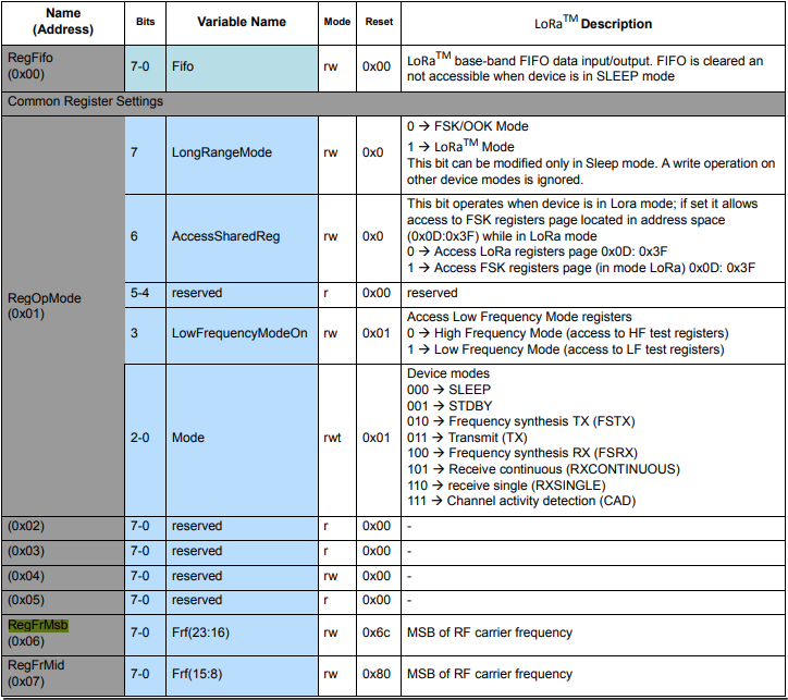
The next step was to read an array of bytes, using spiDevice.TransferFullDuplex. The SX127X transmit/receive frequency is specified in registers 0x06 RegFrMSB, 0x07 RegFrMid, and 0x08 RegFrLsb. The default frequency is 868MHz which is 0xE4, 0xC0, 0x00
static void TransferFullDuplexBufferBytesRead()
{
	const byte length = 3;
	byte[] writeBuffer = new byte[length + 1];
	byte[] readBuffer = new byte[length + 1];

	// Read the frequency which is 3 bytes RegFrMsb 0x6c, RegFrMid 0x80, RegFrLsb 0x00
	writeBuffer[0] = 0x06; //

	// Works, have to point at unused CS0/CS1, others could be a problem is another another SPI device is on on CS0/CS1
	//var settings = new SpiConnectionSettings(0)
	var settings = new SpiConnectionSettings(0, 0)
	//var settings = new SpiConnectionSettings(0, 1)
	{
		ClockFrequency = 5000000,
		Mode = SpiMode.Mode0,   // From SemTech docs pg 80 CPOL=0, CPHA=0
	};

	SpiDevice spiDevice = SpiDevice.Create(settings);

	spiDevice.TransferFullDuplex(writeBuffer, readBuffer);

	Console.WriteLine($"Register 0x06-0x{readBuffer[1]:x2} 0x07-0x{readBuffer[2]:x2} 0x08-0x{readBuffer[3]:x2}");
}
-------------------------------------------------------------------
You may only use the Microsoft .NET Core Debugger (vsdbg) with
Visual Studio Code, Visual Studio or Visual Studio for Mac software
to help you develop and test your applications.
-------------------------------------------------------------------
Loaded '/usr/lib/dotnet/shared/Microsoft.NETCore.App/5.0.4/System.Private.CoreLib.dll'. Skipped loading symbols. Module is optimized and the debugger option 'Just My Code' is enabled.
...
Loaded '/usr/lib/dotnet/shared/Microsoft.NETCore.App/5.0.4/Microsoft.Win32.Primitives.dll'. Skipped loading symbols. Module is optimized and the debugger option 'Just My Code' is enabled.
Register 0x06-0xe4 0x07-0xc0 0x08-0x00
The final step was write an array of bytes, using spiDevice.TransferFullDuplex to change the transmit/receive frequency to 915MHz. To write a value the first bit of the address byte must be set to 1 hence the 0x86 RegFrMsb address.
static void TransferFullDuplexBufferBytesWrite()
{
	const byte length = 3;
	byte[] writeBuffer = new byte[length + 1];
	byte[] readBuffer = new byte[length + 1];

	// Write the frequency which is 3 bytes RegFrMsb 0x6c, RegFrMid 0x80, RegFrLsb or with 0x00 the write mask
	writeBuffer[0] = 0x86 ;

	// Works, have to point at unused CS0/CS1, others could be a problem is another another SPI device is on on CS0/CS1
	//var settings = new SpiConnectionSettings(0)
	var settings = new SpiConnectionSettings(0, 0)
	//var settings = new SpiConnectionSettings(0, 1)
	{
		ClockFrequency = 5000000,
		Mode = SpiMode.Mode0,   // From SemTech docs pg 80 CPOL=0, CPHA=0
	};

	SpiDevice spiDevice = SpiDevice.Create(settings);

	// Set the frequency to 915MHz
	writeBuffer[1] = 0xE4;
	writeBuffer[2] = 0xC0;
	writeBuffer[3] = 0x00;

	spiDevice.TransferFullDuplex(writeBuffer, readBuffer);
}
-------------------------------------------------------------------
You may only use the Microsoft .NET Core Debugger (vsdbg) with
Visual Studio Code, Visual Studio or Visual Studio for Mac software
to help you develop and test your applications.
-------------------------------------------------------------------
Loaded '/usr/lib/dotnet/shared/Microsoft.NETCore.App/5.0.4/System.Private.CoreLib.dll'. Skipped loading symbols. Module is optimized and the debugger option 'Just My Code' is enabled.
...
Loaded '/usr/lib/dotnet/shared/Microsoft.NETCore.App/5.0.4/Microsoft.Win32.Primitives.dll'. Skipped loading symbols. Module is optimized and the debugger option 'Just My Code' is enabled.
Register 0x06-0x6c 0x07-0x80 0x08-0x00
Register 0x06-0xe4 0x07-0xc0 0x08-0x00
The program 'dotnet' has exited with code 0 (0x0).
Summary
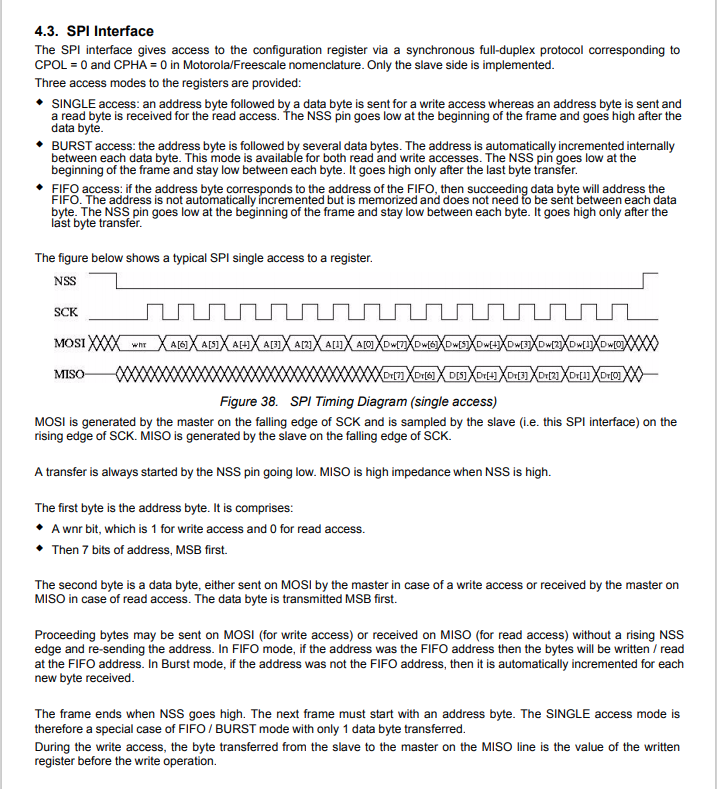
This exceptionally long post was to highlight that with SPI it’s all about timing, first read the datasheet, then build code to validate your understanding.
SX127X SPI interface timing diagram
Some platforms have native TransferSequential implementations but the dotNet/IoT library only has TransferFullDuplex. SPI hardware is always full duplex, if “sequential” is available the implementation will write the provided bytes and then follow them with zeros to read the requested bytes.
Grove – 4 pin Female Jumper to Grove 4 pin Conversion Cable USD3.90
The two sockets on the main board aren’t Grove compatible so I used the 4 pin female to Grove 4 pin conversion cable to connect the temperature and humidity sensor.
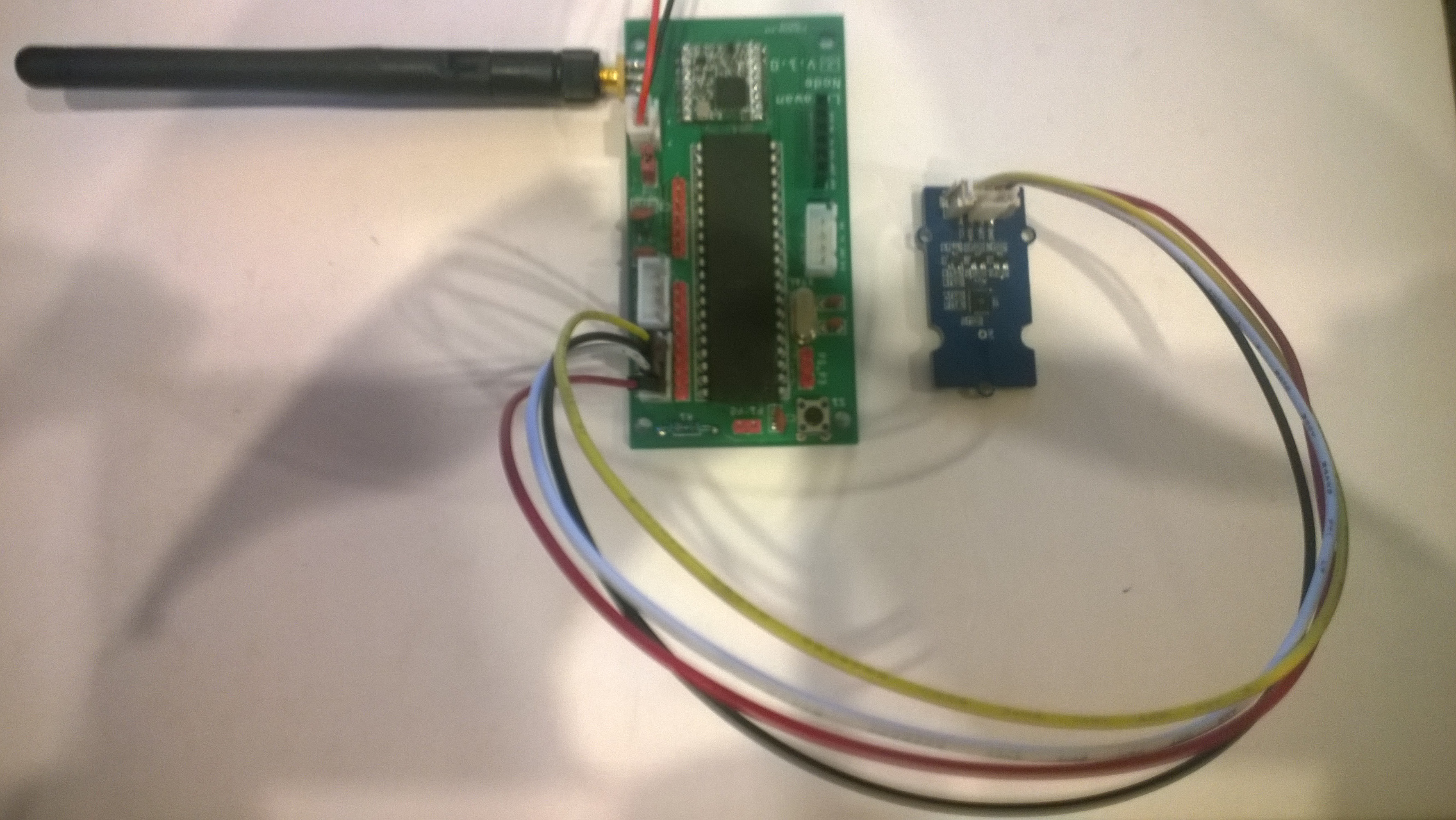
STM32 Blue Pill LoRaWAN node test rig
I used a modified version of my Arduino client code which worked after I got the pin reset pin sorted and the female sockets in the right order.
/*
  Copyright ® 2019 July devMobile Software, All Rights Reserved

  THIS CODE AND INFORMATION IS PROVIDED "AS IS" WITHOUT WARRANTY OF ANY
  KIND, EITHER EXPRESSED OR IMPLIED, INCLUDING BUT NOT LIMITED TO THE
  IMPLIED WARRANTIES OF MERCHANTABILITY AND/OR FITNESS FOR A PARTICULAR
  PURPOSE.

  Adapted from LoRa Duplex communication with Sync Word

  Sends temperature & humidity data from Seeedstudio

  https://www.seeedstudio.com/Grove-Temperature-Humidity-Sensor-High-Accuracy-Min-p-1921.html

  To my Windows 10 IoT Core RFM 9X library

  https://blog.devmobile.co.nz/2018/09/03/rfm9x-iotcore-payload-addressing/
*/
#include <itoa.h>
#include <SPI.h>
#include <LoRa.h>

#include <TH02_dev.h>

#define DEBUG
//#define DEBUG_TELEMETRY
//#define DEBUG_LORA

// LoRa field gateway configuration (these settings must match your field gateway)
const char DeviceAddress[] = {"BLUEPILL"};

// Azure IoT Hub FieldGateway
const char FieldGatewayAddress[] = {"LoRaIoT1"};
const float FieldGatewayFrequency =  915000000.0;
const byte FieldGatewaySyncWord = 0x12 ;

// Bluepill hardware configuration
const int ChipSelectPin = PA4;
const int InterruptPin = PA0;
const int ResetPin = -1;

// LoRa radio payload configuration
const byte SensorIdValueSeperator = ' ' ;
const byte SensorReadingSeperator = ',' ;
const byte PayloadSizeMaximum = 64 ;
byte payload[PayloadSizeMaximum];
byte payloadLength = 0 ;

const int LoopDelaySeconds = 300 ;

// Sensor configuration
const char SensorIdTemperature[] = {"t"};
const char SensorIdHumidity[] = {"h"};


void setup()
{
  Serial.begin(9600);
#ifdef DEBUG
  while (!Serial);
#endif
  Serial.println("Setup called");

  Serial.println("LoRa setup start");

  // override the default chip select and reset pins
  LoRa.setPins(ChipSelectPin, ResetPin, InterruptPin);
  if (!LoRa.begin(FieldGatewayFrequency))
  {
    Serial.println("LoRa begin failed");
    while (true); // Drop into endless loop requiring restart
  }

  // Need to do this so field gateways pays attention to messsages from this device
  LoRa.enableCrc();
  LoRa.setSyncWord(FieldGatewaySyncWord);

#ifdef DEBUG_LORA
  LoRa.dumpRegisters(Serial);
#endif
  Serial.println("LoRa setup done.");

  PayloadHeader((byte*)FieldGatewayAddress, strlen(FieldGatewayAddress), (byte*)DeviceAddress, strlen(DeviceAddress));

 // Configure the Seeedstudio TH02 temperature & humidity sensor
  Serial.println("TH02 setup");
  TH02.begin();
  delay(100);
  Serial.println("TH02 Setup done");

  Serial.println("Setup done");
}

void loop() {
  // read the value from the sensor:
  double temperature = TH02.ReadTemperature();
  double humidity = TH02.ReadHumidity();

  Serial.print("Humidity: ");
  Serial.print(humidity, 0);
  Serial.print(" %\t");
  Serial.print("Temperature: ");
  Serial.print(temperature, 1);
  Serial.println(" *C");

  PayloadReset();

  PayloadAdd(SensorIdHumidity, humidity, 0) ;
  PayloadAdd(SensorIdTemperature, temperature, 1) ;

  LoRa.beginPacket();
  LoRa.write(payload, payloadLength);
  LoRa.endPacket();

  Serial.println("Loop done");

  delay(LoopDelaySeconds * 1000);
}


void PayloadHeader( byte *to, byte toAddressLength, byte *from, byte fromAddressLength)
{
  byte addressesLength = toAddressLength + fromAddressLength ;

#ifdef DEBUG_TELEMETRY
  Serial.println("PayloadHeader- ");
  Serial.print( "To Address len:");
  Serial.print( toAddressLength );
  Serial.print( " From Address len:");
  Serial.print( fromAddressLength );
  Serial.print( " Addresses length:");
  Serial.print( addressesLength );
  Serial.println( );
#endif

  payloadLength = 0 ;

  // prepare the payload header with "To" Address length (top nibble) and "From" address length (bottom nibble)
  payload[payloadLength] = (toAddressLength << 4) | fromAddressLength ;
  payloadLength += 1;

  // Copy the "To" address into payload
  memcpy(&payload[payloadLength], to, toAddressLength);
  payloadLength += toAddressLength ;

  // Copy the "From" into payload
  memcpy(&payload[payloadLength], from, fromAddressLength);
  payloadLength += fromAddressLength ;
}


void PayloadAdd( const char *sensorId, float value, byte decimalPlaces)
{
  byte sensorIdLength = strlen( sensorId ) ;

#ifdef DEBUG_TELEMETRY
  Serial.println("PayloadAdd-float ");
  Serial.print( "SensorId:");
  Serial.print( sensorId );
  Serial.print( " sensorIdLen:");
  Serial.print( sensorIdLength );
  Serial.print( " Value:");
  Serial.print( value, decimalPlaces );
  Serial.print( " payloadLength:");
  Serial.print( payloadLength);
#endif

  memcpy( &payload[payloadLength], sensorId,  sensorIdLength) ;
  payloadLength += sensorIdLength ;
  payload[ payloadLength] = SensorIdValueSeperator;
  payloadLength += 1 ;
  payloadLength += strlen( dtostrf(value, -1, decimalPlaces, (char *)&payload[payloadLength]));
  payload[ payloadLength] = SensorReadingSeperator;
  payloadLength += 1 ;

#ifdef DEBUG_TELEMETRY
  Serial.print( " payloadLength:");
  Serial.print( payloadLength);
  Serial.println( );
#endif
}


void PayloadAdd( const char *sensorId, int value )
{
  byte sensorIdLength = strlen( sensorId ) ;

#ifdef DEBUG_TELEMETRY
  Serial.println("PayloadAdd-int ");
  Serial.print( "SensorId:");
  Serial.print( sensorId );
  Serial.print( " sensorIdLen:");
  Serial.print( sensorIdLength );
  Serial.print( " Value:");
  Serial.print( value );
  Serial.print( " payloadLength:");
  Serial.print( payloadLength);
#endif

  memcpy( &payload[payloadLength], sensorId,  sensorIdLength) ;
  payloadLength += sensorIdLength ;
  payload[ payloadLength] = SensorIdValueSeperator;
  payloadLength += 1 ;
  payloadLength += strlen( itoa( value, (char *)&payload[payloadLength], 10));
  payload[ payloadLength] = SensorReadingSeperator;
  payloadLength += 1 ;

#ifdef DEBUG_TELEMETRY
  Serial.print( " payloadLength:");
  Serial.print( payloadLength);
  Serial.println( );
#endif
}

void PayloadAdd( const char *sensorId, unsigned int value )
{
  byte sensorIdLength = strlen( sensorId ) ;

#ifdef DEBUG_TELEMETRY
  Serial.println("PayloadAdd-unsigned int ");
  Serial.print( "SensorId:");
  Serial.print( sensorId );
  Serial.print( " sensorIdLen:");
  Serial.print( sensorIdLength );
  Serial.print( " Value:");
  Serial.print( value );
  Serial.print( " payloadLength:");
  Serial.print( payloadLength);
#endif

  memcpy( &payload[payloadLength], sensorId,  sensorIdLength) ;
  payloadLength += sensorIdLength ;
  payload[ payloadLength] = SensorIdValueSeperator;
  payloadLength += 1 ;
  payloadLength += strlen( utoa( value, (char *)&payload[payloadLength], 10));
  payload[ payloadLength] = SensorReadingSeperator;
  payloadLength += 1 ;

#ifdef DEBUG_TELEMETRY
  Serial.print( " payloadLength:");
  Serial.print( payloadLength);
  Serial.println( );
#endif
}


void PayloadReset()
{
  byte fromAddressLength = payload[0] & 0xf ;
  byte toAddressLength = payload[0] >> 4 ;
  byte addressesLength = toAddressLength + fromAddressLength ;

  payloadLength = addressesLength + 1;

#ifdef DEBUG_TELEMETRY
  Serial.println("PayloadReset- ");
  Serial.print( "To Address len:");
  Serial.print( toAddressLength );
  Serial.print( " From Address len:");
  Serial.print( fromAddressLength );
  Serial.print( " Addresses length:");
  Serial.print( addressesLength );
  Serial.println( );
#endif
}
To get the application to compile I also had to include itoa.h rather than stdlib.h.
maple_loader v0.1
Resetting to bootloader via DTR pulse
[Reset via USB Serial Failed! Did you select the right serial port?]
Searching for DFU device [1EAF:0003]...
Assuming the board is in perpetual bootloader mode and continuing to attempt dfu programming...

dfu-util - (C) 2007-2008 by OpenMoko Inc.
Initially I had some problems deploying my software because I hadn’t followed the instructions and run the installation batch file.
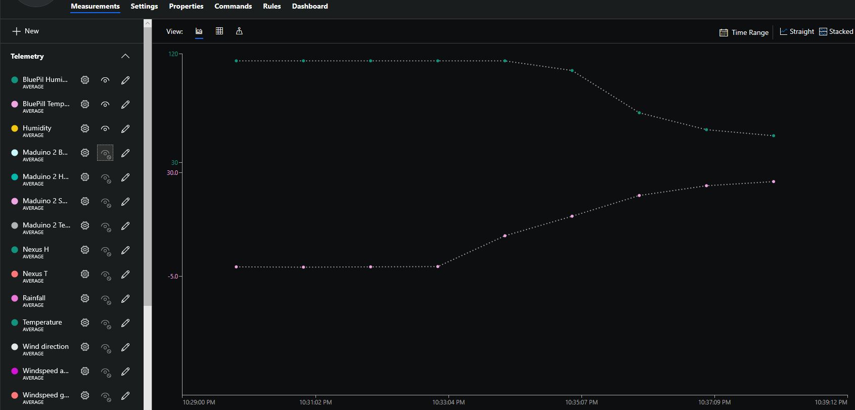
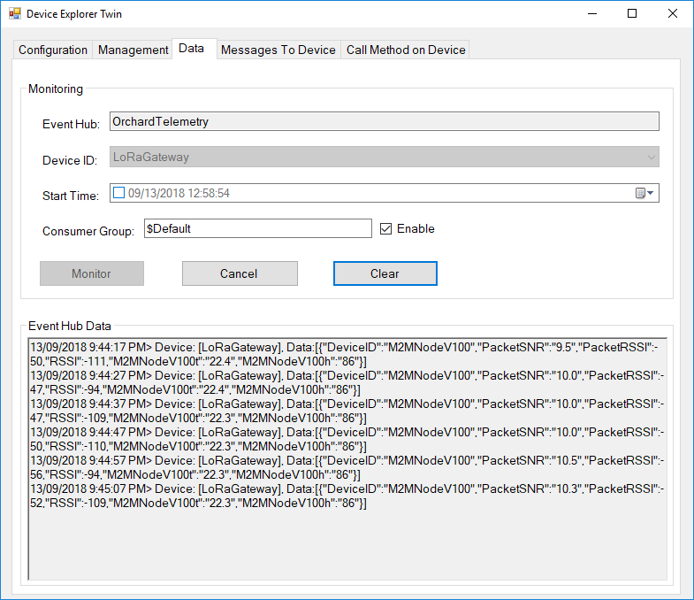
I configured the device to upload to my Azure IoT Hub/Azure IoT Central gateway and after getting the device name configuration right it has been running reliably for a couple of days
Azure IoT Central Temperature and humidity
The device was sitting outside on the deck and rapid increase in temperature is me bringing it inside.
4 pin Female Jumper to Grove 4 pin Conversion Cable USD2.90
The code is pretty basic (like the other samples), it shows how to pack the payload and set the necessary RFM9X/SX127XLoRa module configuration, has no power conservation, advanced wireless configuration etc.
The Grove 4 pin Female Jumper to Grove 4 pin Conversion Cable was a quick & convenient way to get the I2C Grove temperature and humidity sensor connected up.
Seeedstudio Temperature & Humidity Sensor USD11.50
4 pin Female Jumper to Grove 4 pin Conversion Cable USD2.90
The code is pretty basic, it shows how to pack the payload and set the necessary RFM9X/SX127XLoRa module configuration, has no power conservation, advanced wireless configuration etc.
The Grove 4 pin Female Jumper to Grove 4 pin Conversion Cable was a quick & convenient way to get the I2C Grove temperature and humidity sensor connected up.