The second prototype of “transforming” telemetry data used C# code complied and binary cached on demand. The HiveMQClient based application subscribes to topics (devices publishing environmental measurements) and then republishes them to multiple topics.
public class messageTransformer : IMessageTransformer
{
   public MQTT5PublishMessage[] Transform(MQTT5PublishMessage message)
   {
      if (message.Payload is null)
      {
         return [];
      }

      var payload = Encoding.UTF8.GetString(message.Payload);

      // Simple transformations: convert to both upper and lower case
      var toLower = new MQTT5PublishMessage
      {
         Topic = message.Topic,
         Payload = Encoding.UTF8.GetBytes(payload.ToLower()),
         QoS = QualityOfService.AtLeastOnceDelivery
      };

      var toUpper = new MQTT5PublishMessage
      {
         Topic = message.Topic,
         Payload = Encoding.UTF8.GetBytes(payload.ToUpper()),
         QoS = QualityOfService.AtLeastOnceDelivery
      };

      return [toLower, toUpper];
   }
}
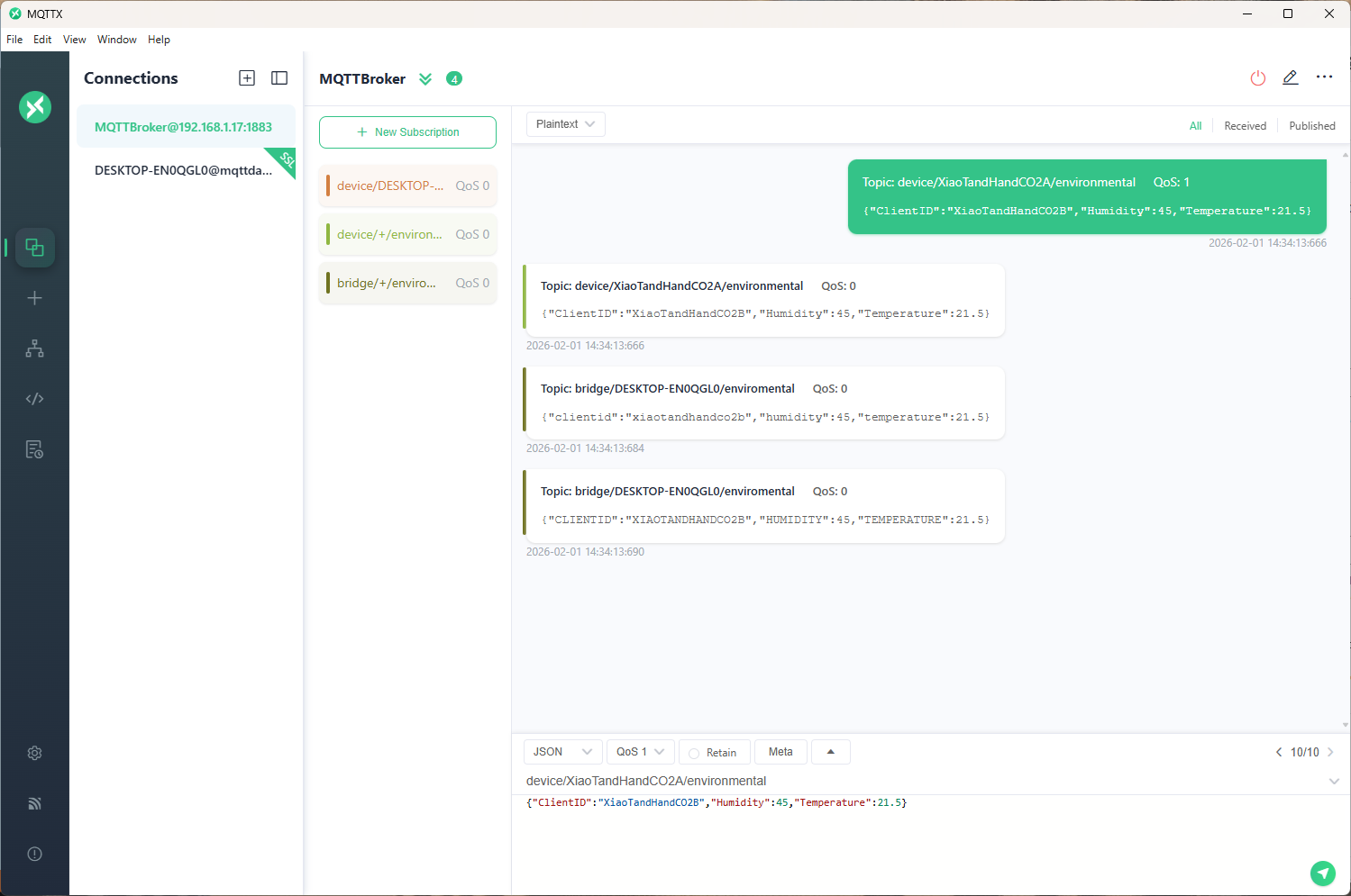
The sample C# code (LowerUpper.cs) implements the IMessageTransformer interface and republishes both lower and upper case versions of the message.
Once the transformer had been loaded then compiled there was no noticeable difference between the application, loaded from constant string, and loaded from external file versions.
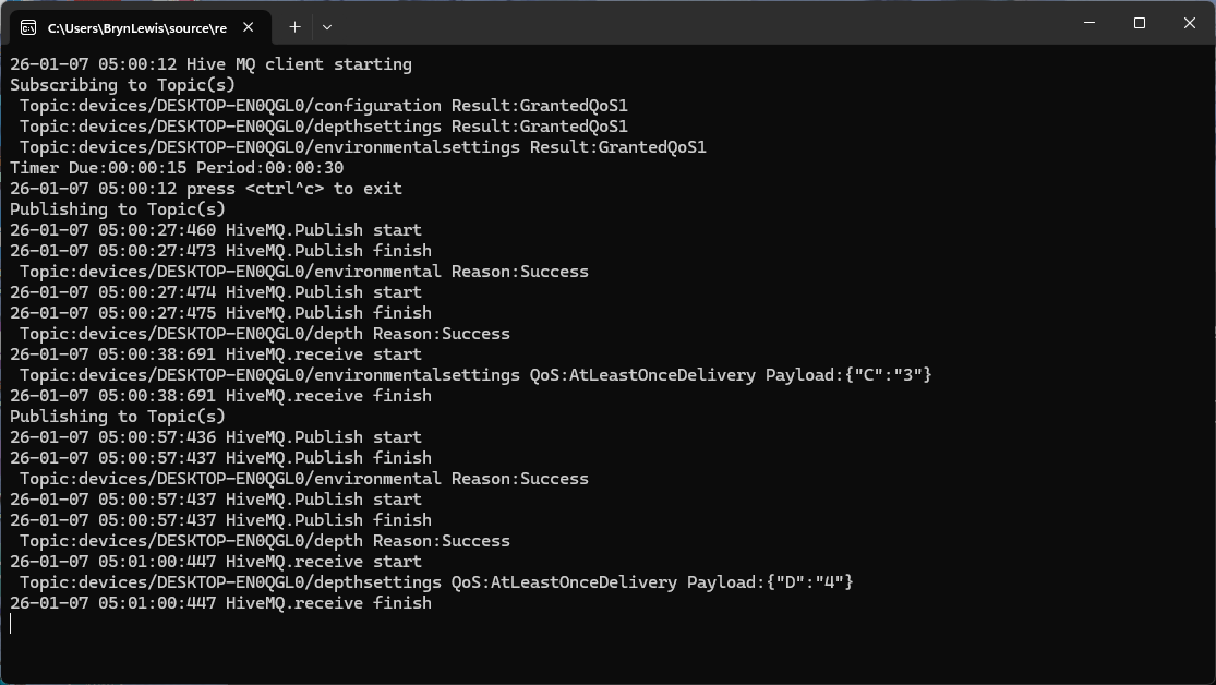
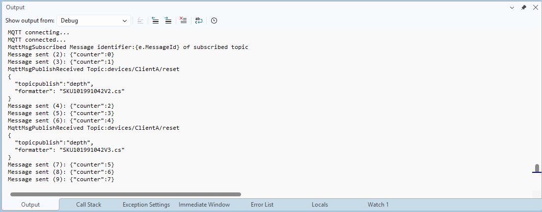
private static void OnMessageReceived(object? sender, HiveMQtt.Client.Events.OnMessageReceivedEventArgs e)
{
   HiveMQClient client = (HiveMQClient)sender!;

   Console.WriteLine($"{DateTime.UtcNow:yy-MM-dd HH:mm:ss:fff} HiveMQ.receive start");
   Console.WriteLine($" Topic:{e.PublishMessage.Topic} QoS:{e.PublishMessage.QoS} Payload:{e.PublishMessage.PayloadAsString}");

   Console.WriteLine($"{DateTime.UtcNow:yy-MM-dd HH:mm:ss:fff} HiveMQ.Publish start");
   foreach (string topic in _applicationSettings.PublishTopics.Split(',', StringSplitOptions.RemoveEmptyEntries | StringSplitOptions.TrimEntries))
   {
      e.PublishMessage.Topic = string.Format(topic, _applicationSettings.ClientId);

      var transformer = _scriptEngine.GetTransformer();

      if (transformer is null)
      {
         Console.WriteLine($"{DateTime.UtcNow:yy-MM-dd HH:mm:ss:fff} Transformer is null");
         return;
      }

      var transformedMessages = transformer.Transform(e.PublishMessage);
      if (transformedMessages is null)
      {
         Console.WriteLine($"{DateTime.UtcNow:yy-MM-dd HH:mm:ss:fff} Transformer returned null");
         return;
      }

      if (transformedMessages.Length == 0)
      {
         Console.WriteLine($"{DateTime.UtcNow:yy-MM-dd HH:mm:ss:fff} Transformer returned no messages");
         return;
      }

      foreach (MQTT5PublishMessage message in transformer.Transform(e.PublishMessage))
      {
         if (message is null)
         {
            Console.WriteLine($"{DateTime.UtcNow:yy-MM-dd HH:mm:ss:fff} Transformer message is null");

            continue;
         }

         try
         {
            Console.WriteLine($"{DateTime.UtcNow:yy-MM-dd HH:mm:ss:fff} Topic:{e.PublishMessage.Topic} HiveMQ Publish start ");

            var resultPublish = client.PublishAsync(message).GetAwaiter().GetResult();

            Console.WriteLine($"{DateTime.UtcNow:yy-MM-dd HH:mm:ss:fff} Published:{resultPublish.QoS1ReasonCode} {resultPublish.QoS2ReasonCode}");
         }
         catch (Exception ex)
         {
            Console.WriteLine($"{DateTime.UtcNow:yy-MM-dd HH:mm:ss:fff} HiveMQ Publish exception {ex.Message}");
         }
      }
   }
   Console.WriteLine($"{DateTime.UtcNow:yy-MM-dd HH:mm:ss:fff} HiveMQ.Receive finish");
}
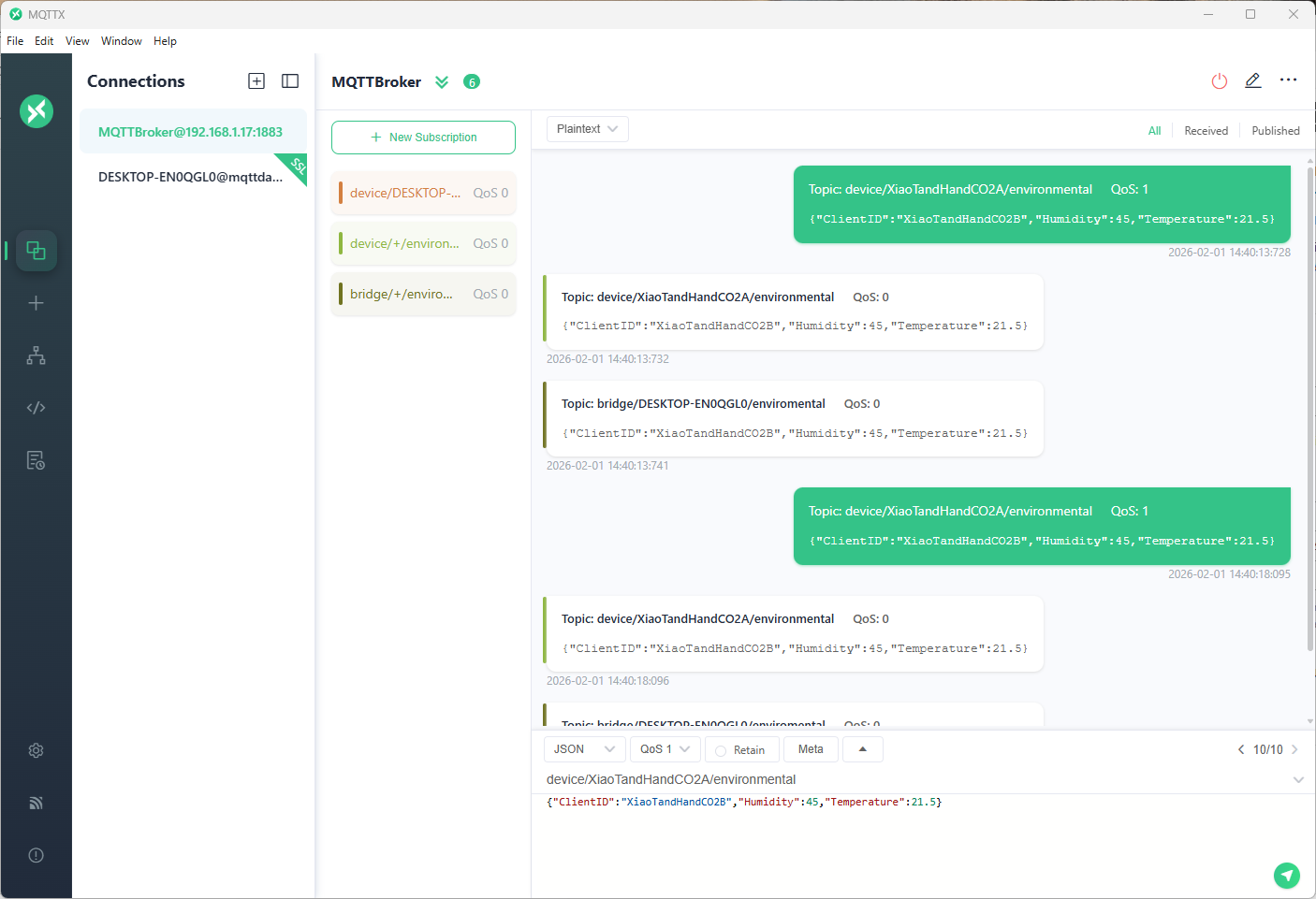
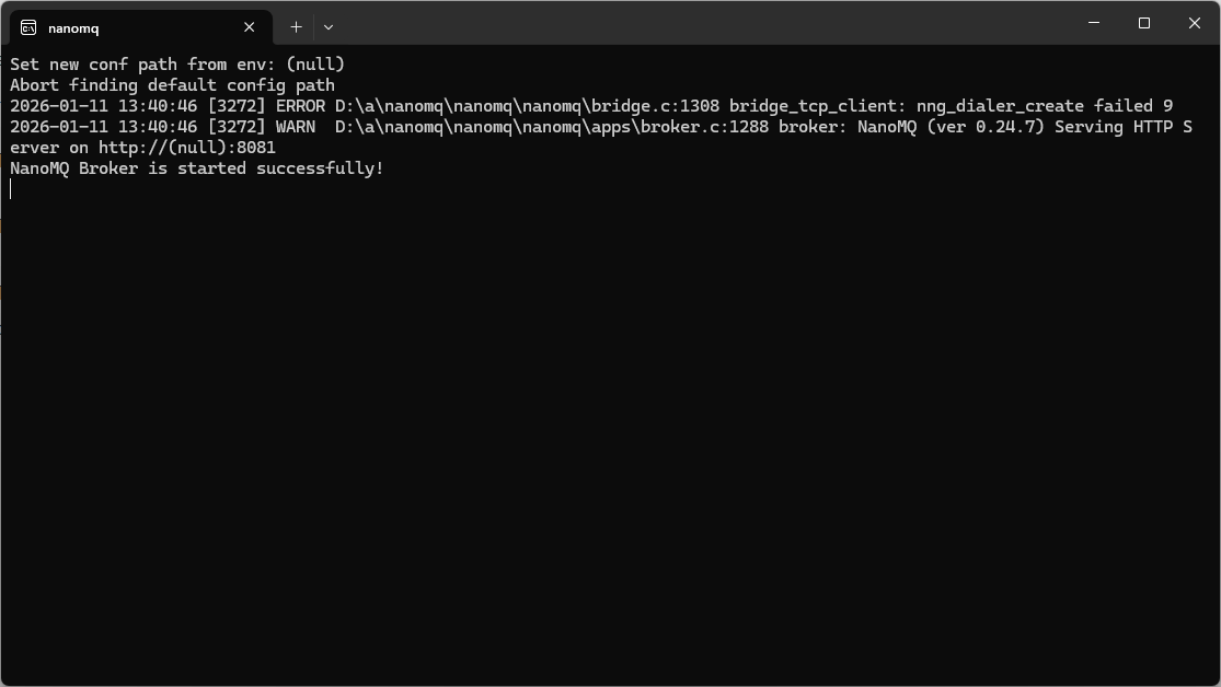
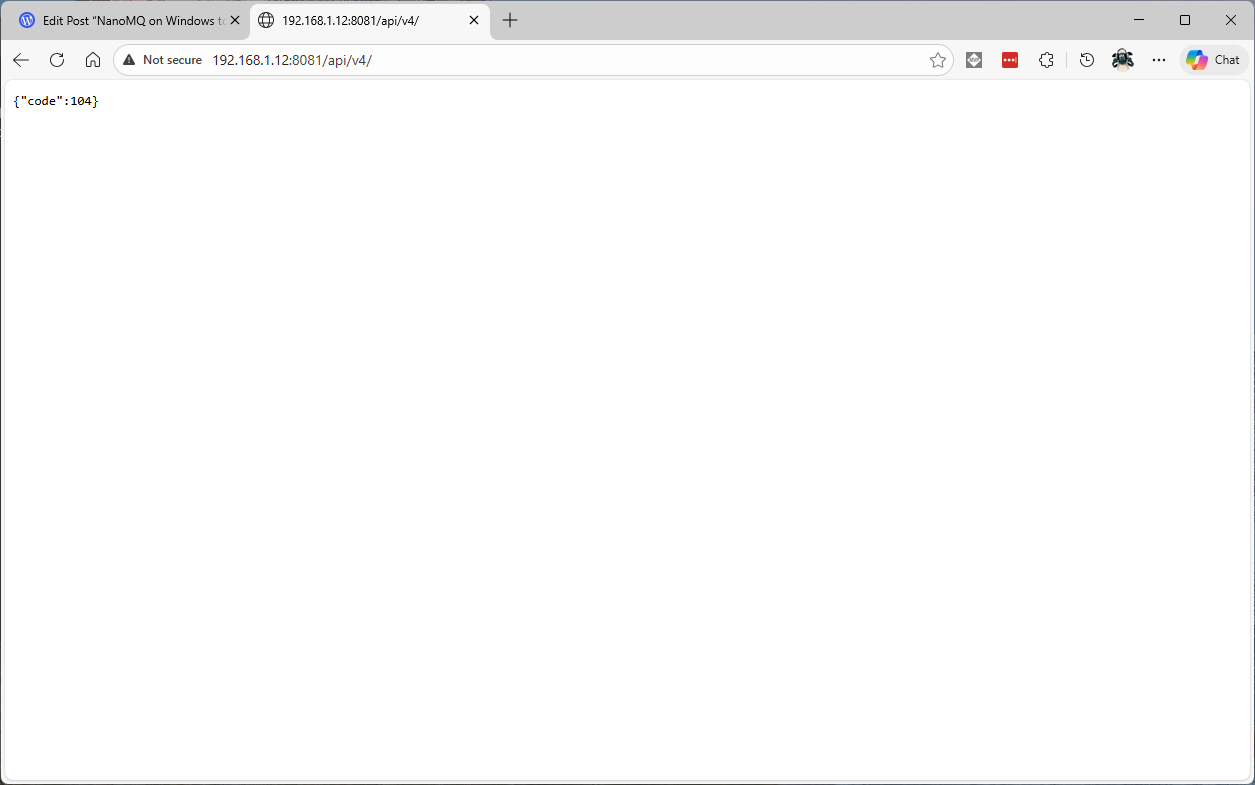
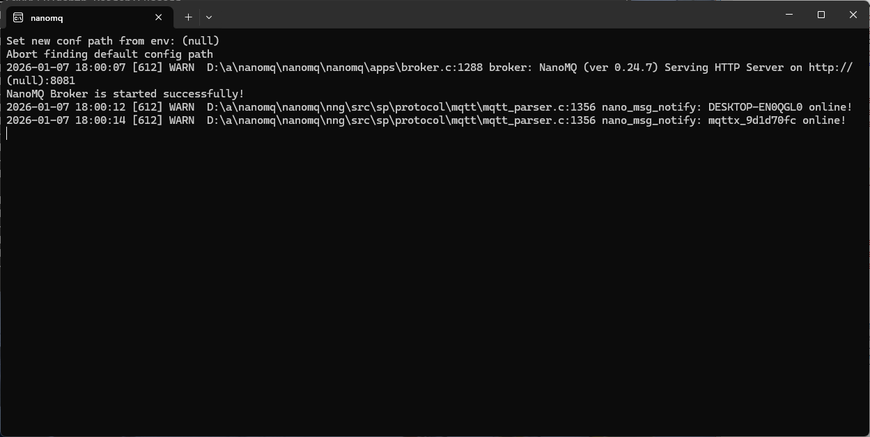
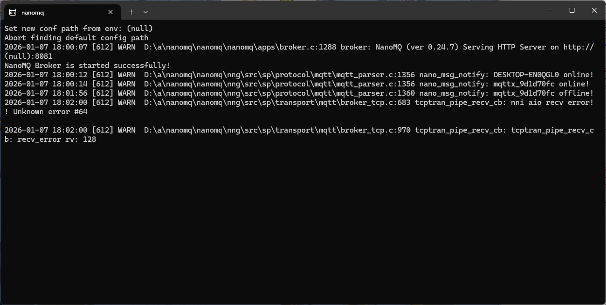
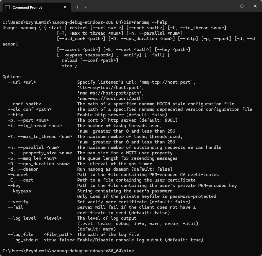
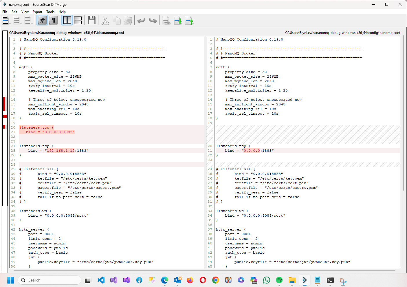
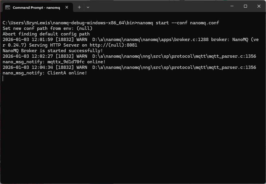
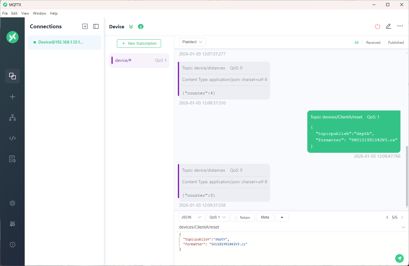
I used a local instance of NanoMQ: An Ultra-lightweight MQTT Broker for IoT Edge for testing
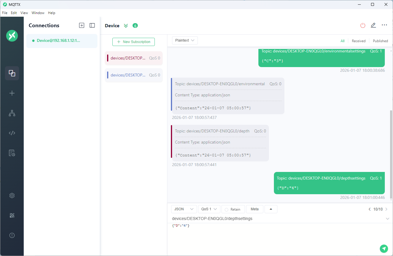
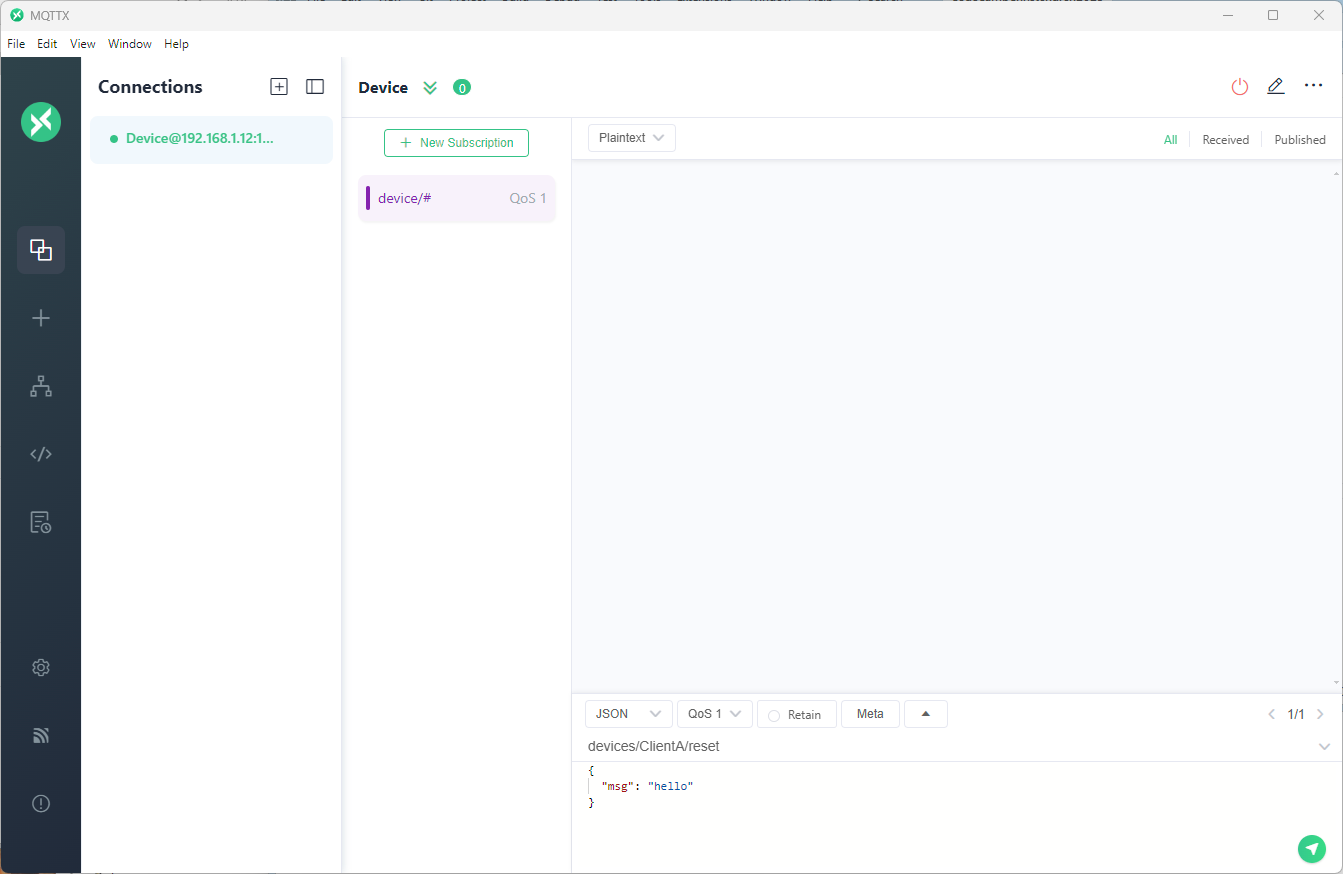
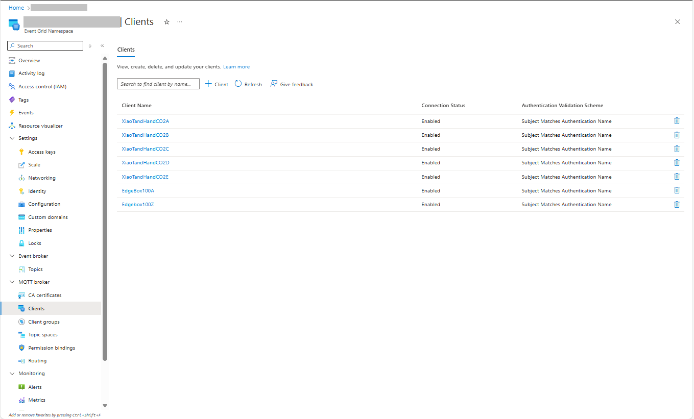
The MQTTX application subscribed to topics that devices (XiaoTandHandCO2A, XiaoTandHandCO2B etc.) and the simulated bridge (in my case DESKTOP-EN0QGL0) published.