Receive Interrupt: Rasmatic/RFM69-Arduino-Library
I started with the receive basic code, the first step was to add a parameter to the constructor for the interrupt pin connected to the RFM69HCW and configuring the GPIO pin. I then moved the code for getting the message payload from the device FIFO to my new interrupt handler.
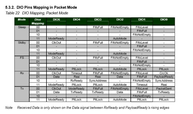
The Adafruit Radio Bonnet has pin 22 connected to the DIO0 pin the RFM69HCW so I set the RegDioMapping1 register to trigger DIO0 on PayloadReady. (Ignored other flags)
/*
Copyright ® 2019 June devMobile Software, All Rights Reserved
MIT License
Permission is hereby granted, free of charge, to any person obtaining a copy
of this software and associated documentation files (the "Software"), to deal
in the Software without restriction, including without limitation the rights
to use, copy, modify, merge, publish, distribute, sublicense, and/or sell
copies of the Software, and to permit persons to whom the Software is
furnished to do so, subject to the following conditions:
The above copyright notice and this permission notice shall be included in all
copies or substantial portions of the Software.
THE SOFTWARE IS PROVIDED "AS IS", WITHOUT WARRANTY OF ANY KIND, EXPRESS OR
IMPLIED, INCLUDING BUT NOT LIMITED TO THE WARRANTIES OF MERCHANTABILITY,
FITNESS FOR A PARTICULAR PURPOSE AND NONINFRINGEMENT. IN NO EVENT SHALL THE
AUTHORS OR COPYRIGHT HOLDERS BE LIABLE FOR ANY CLAIM, DAMAGES OR OTHER
LIABILITY, WHETHER IN AN ACTION OF CONTRACT, TORT OR OTHERWISE, ARISING FROM,
OUT OF OR IN CONNECTION WITH THE SOFTWARE OR THE USE OR OTHER DEALINGS IN THE
SOFTWARE
*/
namespace devMobile.IoT.Rfm69Hcw.ReceiveInterrupt
{
using System;
using System.Diagnostics;
using System.Runtime.InteropServices.WindowsRuntime;
using System.Text;
using System.Threading.Tasks;
using Windows.ApplicationModel.Background;
using Windows.Devices.Gpio;
using Windows.Devices.Spi;
public sealed class Rfm69HcwDevice
{
private SpiDevice Rfm69Hcw;
private GpioPin InterruptGpioPin = null;
private const byte RegisterAddressReadMask = 0X7f;
private const byte RegisterAddressWriteMask = 0x80;
public Rfm69HcwDevice(int chipSelectPin, int resetPin, int interruptPin)
{
SpiController spiController = SpiController.GetDefaultAsync().AsTask().GetAwaiter().GetResult();
var settings = new SpiConnectionSettings(chipSelectPin)
{
ClockFrequency = 500000,
Mode = SpiMode.Mode0,
};
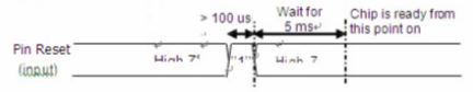
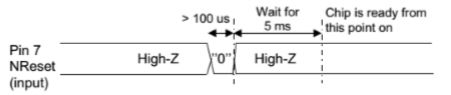
// Factory reset pin configuration
GpioController gpioController = GpioController.GetDefault();
GpioPin resetGpioPin = gpioController.OpenPin(resetPin);
resetGpioPin.SetDriveMode(GpioPinDriveMode.Output);
resetGpioPin.Write(GpioPinValue.High);
Task.Delay(100);
resetGpioPin.Write(GpioPinValue.Low);
Task.Delay(10);
// Interrupt pin for RX message & TX done notification
InterruptGpioPin = gpioController.OpenPin(interruptPin);
resetGpioPin.SetDriveMode(GpioPinDriveMode.Input);
InterruptGpioPin.ValueChanged += InterruptGpioPin_ValueChanged;
Rfm69Hcw = spiController.GetDevice(settings);
}
private void InterruptGpioPin_ValueChanged(GpioPin sender, GpioPinValueChangedEventArgs args)
{
if (args.Edge != GpioPinEdge.RisingEdge)
{
return;
}
byte irqFlags = this.RegisterReadByte(0x28); // RegIrqFlags2
Debug.WriteLine("{0:HH:mm:ss} RegIrqFlags {1}", DateTime.Now, Convert.ToString((byte)irqFlags, 2).PadLeft(8, '0'));
if ((irqFlags & 0b00000100) == 0b00000100) // PayLoadReady set
{
// Read the length of the buffer
byte numberOfBytes = this.RegisterReadByte(0x0);
// Allocate buffer for message
byte[] messageBytes = new byte[numberOfBytes];
for (int i = 0; i < numberOfBytes; i++)
{
messageBytes[i] = this.RegisterReadByte(0x00); // RegFifo
}
string messageText = UTF8Encoding.UTF8.GetString(messageBytes);
Debug.WriteLine("{0:HH:mm:ss} Received {1} byte message {2}", DateTime.Now, messageBytes.Length, messageText);
}
}
public Byte RegisterReadByte(byte address)
{
byte[] writeBuffer = new byte[] { address &= RegisterAddressReadMask };
byte[] readBuffer = new byte[1];
Debug.Assert(Rfm69Hcw != null);
Rfm69Hcw.TransferSequential(writeBuffer, readBuffer);
return readBuffer[0];
}
public byte[] RegisterRead(byte address, int length)
{
byte[] writeBuffer = new byte[] { address &= RegisterAddressReadMask };
byte[] readBuffer = new byte[length];
Debug.Assert(Rfm69Hcw != null);
Rfm69Hcw.TransferSequential(writeBuffer, readBuffer);
return readBuffer;
}
public void RegisterWriteByte(byte address, byte value)
{
byte[] writeBuffer = new byte[] { address |= RegisterAddressWriteMask, value };
Debug.Assert(Rfm69Hcw != null);
Rfm69Hcw.Write(writeBuffer);
}
public void RegisterWrite(byte address, [ReadOnlyArray()] byte[] bytes)
{
byte[] writeBuffer = new byte[1 + bytes.Length];
Debug.Assert(Rfm69Hcw != null);
Array.Copy(bytes, 0, writeBuffer, 1, bytes.Length);
writeBuffer[0] = address |= RegisterAddressWriteMask;
Rfm69Hcw.Write(writeBuffer);
}
public void RegisterDump()
{
Debug.WriteLine("Register dump");
for (byte registerIndex = 0; registerIndex <= 0x3D; registerIndex++)
{
byte registerValue = this.RegisterReadByte(registerIndex);
Debug.WriteLine("Register 0x{0:x2} - Value 0X{1:x2} - Bits {2}", registerIndex, registerValue, Convert.ToString(registerValue, 2).PadLeft(8, '0'));
}
}
}
public sealed class StartupTask : IBackgroundTask
{
private const int ChipSelectLine = 1;
private const int ResetPin = 25;
private const int InterruptPin = 22;
private Rfm69HcwDevice rfm69Device = new Rfm69HcwDevice(ChipSelectLine, ResetPin, InterruptPin);
const double RH_RF6M9HCW_FXOSC = 32000000.0;
const double RH_RFM69HCW_FSTEP = RH_RF6M9HCW_FXOSC / 524288.0;
public void Run(IBackgroundTaskInstance taskInstance)
{
//rfm69Device.RegisterDump();
// regOpMode standby
rfm69Device.RegisterWriteByte(0x01, 0b00000100);
// BitRate MSB/LSB
rfm69Device.RegisterWriteByte(0x03, 0x34);
rfm69Device.RegisterWriteByte(0x04, 0x00);
// Calculate the frequency accoring to the datasheett
byte[] bytes = BitConverter.GetBytes((uint)(915000000.0 / RH_RFM69HCW_FSTEP));
Debug.WriteLine("Byte Hex 0x{0:x2} 0x{1:x2} 0x{2:x2} 0x{3:x2}", bytes[0], bytes[1], bytes[2], bytes[3]);
rfm69Device.RegisterWriteByte(0x07, bytes[2]);
rfm69Device.RegisterWriteByte(0x08, bytes[1]);
rfm69Device.RegisterWriteByte(0x09, bytes[0]);
// RegRxBW
rfm69Device.RegisterWriteByte(0x19, 0x2a);
// RegDioMapping1
rfm69Device.RegisterWriteByte(0x26, 0x01);
// Setup preamble length to 16 (default is 3) RegPreambleMsb RegPreambleLsb
rfm69Device.RegisterWriteByte(0x2C, 0x0);
rfm69Device.RegisterWriteByte(0x2D, 0x10);
// RegSyncConfig Set the Sync length and byte values SyncOn + 3 custom sync bytes
rfm69Device.RegisterWriteByte(0x2e, 0x90);
// RegSyncValues1 thru RegSyncValues3
rfm69Device.RegisterWriteByte(0x2f, 0xAA);
rfm69Device.RegisterWriteByte(0x30, 0x2D);
rfm69Device.RegisterWriteByte(0x31, 0xD4);
// RegPacketConfig1 Variable length with CRC on
rfm69Device.RegisterWriteByte(0x37, 0x90);
rfm69Device.RegisterWriteByte(0x01, 0b00010000); // RegOpMode set ReceiveMode
rfm69Device.RegisterDump();
Debug.WriteLine("Receive-Wait");
Task.Delay(-1).Wait();
}
}
}

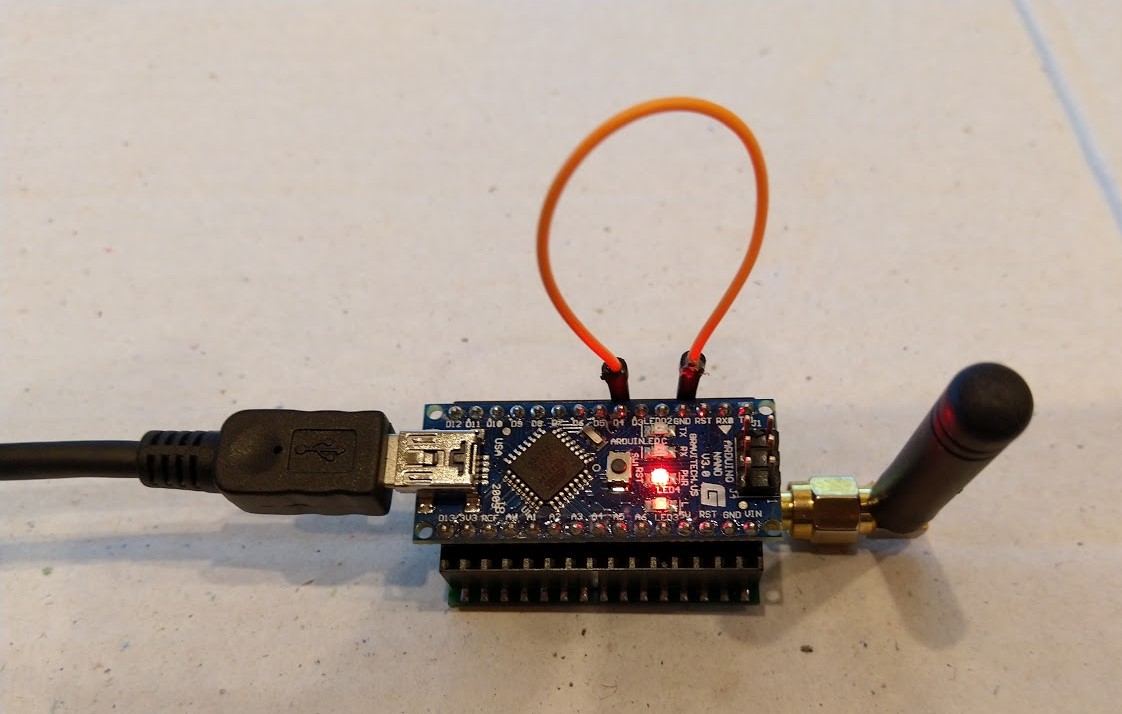
I used the same Arduino device and code as my polled receive sample and after I fixing a couple of typos in my code…
Register dump
Register 0x00 - Value 0X00 - Bits 00000000
Register 0x01 - Value 0X10 - Bits 00010000
...
Register 0x3b - Value 0X00 - Bits 00000000
Register 0x3c - Value 0X0f - Bits 00001111
Register 0x3d - Value 0X02 - Bits 00000010
Receive-Wait
The thread 0xe7c has exited with code 0 (0x0).
The thread 0x9dc has exited with code 0 (0x0).
13:45:56 RegIrqFlags 01000110
13:45:56 Received 13 byte message Hello world:0
13:45:58 RegIrqFlags 01000110
13:45:58 Received 13 byte message Hello world:1
13:46:00 RegIrqFlags 01000110
13:46:00 Received 13 byte message Hello world:2
13:46:02 RegIrqFlags 01000110
13:46:02 Received 13 byte message Hello world:3
13:46:04 RegIrqFlags 01000110
13:46:04 Received 13 byte message Hello world:4
I ran the Windows 10 IoT Core client for several hours and it didn’t appear to drop any messages or have any other issues.