Random wanderings through Microsoft Azure esp. PaaS plumbing, the IoT bits, AI on Micro controllers, AI on Edge Devices, .NET nanoFramework, .NET Core on *nix and ML.NET+ONNX
I had been planning this for a while, then the code broke when I tried to build a version for my SparkFun LoRa Gateway-1-Channel (ESP32). There was a namespace (static configuration class in configuration.cs) collision and the length of SX127XDevice.cs file was getting silly.
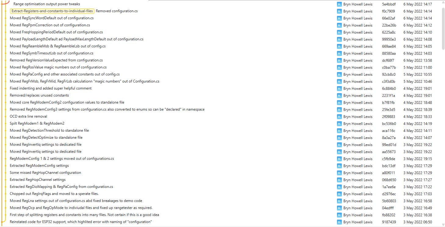
This refactor took a couple of days and really changed the structure of the library.
VS2022 Solution structure after refactoring
I went through the SX127XDevice.cs extracting the enumerations, masks and defaults associated with the registers the library supports.
The library is designed to be a approximate .NET nanoFramework equivalent of Arduino-LoRa so it doesn’t support/implement all of the functionality of the SemtechSX127X. Still got a bit of refactoring to go but the structure is slowly improving.
I use Fork to manage my Github repositories, it’s an excellent product especially as it does a pretty good job of keeping me from screwing up.
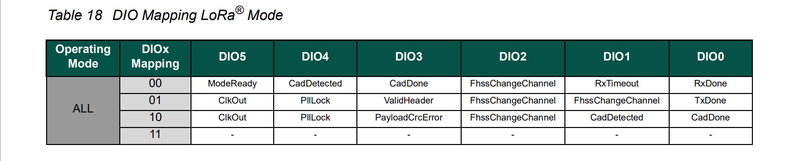
All the previous versions of my.NET nanoFrameworkSemtech SX127X (LoRa® Mode) library only supported a Dio0 (RegDioMapping1 bits 6&7) EventHandler. This version supports mapping Dio0, Dio1, Dio2, Dio3, Dio4 and Dio5.
The SX127XLoRaDeviceClient main now has OnRxTimeout, OnReceive, OnPayloadCrcError, OnValidHeader, OnTransmit, OnChannelActivityDetectionDone, OnFhssChangeChannel, and OnChannelActivityDetected event handlers (Based on RegIrqFlags bit ordering)
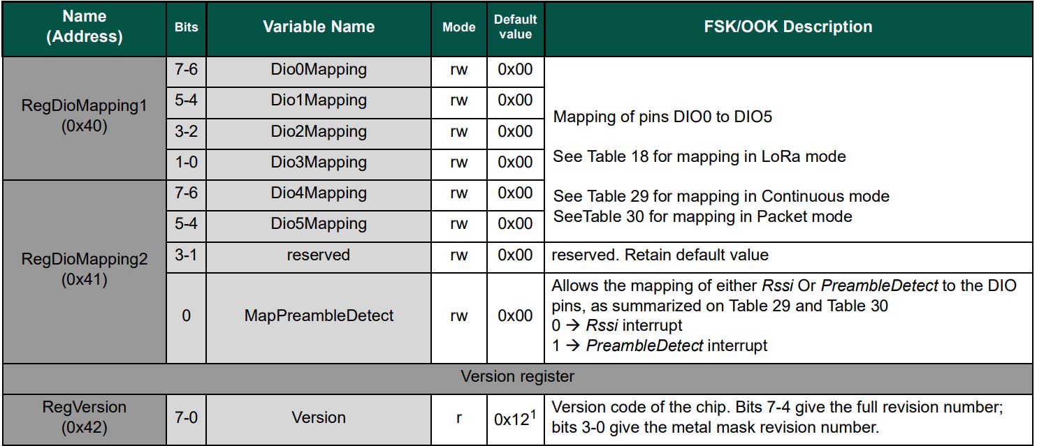
The Dio0 pin number is the only required pin number parameter, the resetPin, and Dio1 thru Dio5 pin numbers are optional. All the RegDioMapping1 and RegDioMapping2 mappings are disabled on intialisation so there should be no events while the SX127X is being configured.
public SX127XDevice(SpiDevice spiDevice, GpioController gpioController,
	int dio0Pin,
	int resetPin = 0, // Odd order so as not to break exisiting code
	int dio1Pin = 0,
	int dio2Pin = 0,
	int dio3Pin = 0,
	int dio4Pin = 0,
	int dio5Pin = 0
	)
{
	_gpioController = gpioController;

	// Factory reset pin configuration
	if (resetPin != 0)
	{
		_resetPin = resetPin;
		_gpioController.OpenPin(resetPin, PinMode.Output);

		_gpioController.Write(resetPin, PinValue.Low);
		Thread.Sleep(20);
		_gpioController.Write(resetPin, PinValue.High);
		Thread.Sleep(50);
	}

	_registerManager = new RegisterManager(spiDevice, RegisterAddressReadMask, RegisterAddressWriteMask);

	// Once the pins setup check that SX127X chip is present
	Byte regVersionValue = _registerManager.ReadByte((byte)Configuration.Registers.RegVersion);
	if (regVersionValue != Configuration.RegVersionValueExpected)
	{
		throw new ApplicationException("Semtech SX127X not found");
	}

	// See Table 18 DIO Mapping LoRa® Mode
	Configuration.RegDioMapping1 regDioMapping1Value = Configuration.RegDioMapping1.Dio0None;
	regDioMapping1Value |= Configuration.RegDioMapping1.Dio1None;
	regDioMapping1Value |= Configuration.RegDioMapping1.Dio2None;
	regDioMapping1Value |= Configuration.RegDioMapping1.Dio3None;
	_registerManager.WriteByte((byte)Configuration.Registers.RegDioMapping1, (byte)regDioMapping1Value);

	// Currently no easy way to test this with available hardware
	//Configuration.RegDioMapping2 regDioMapping2Value = Configuration.RegDioMapping2.Dio4None;
	//regDioMapping2Value = Configuration.RegDioMapping2.Dio5None;
	//_registerManager.WriteByte((byte)Configuration.Registers.RegDioMapping2, (byte)regDioMapping2Value);

	// Interrupt pin for RXDone, TXDone, and CadDone notification
	_gpioController.OpenPin(dio0Pin, PinMode.InputPullDown);
	_gpioController.RegisterCallbackForPinValueChangedEvent(dio0Pin, PinEventTypes.Rising, InterruptGpioPin_ValueChanged);

	// RxTimeout, FhssChangeChannel, and CadDetected
	if (dio1Pin != 0)
	{
		_gpioController.OpenPin(dio1Pin, PinMode.InputPullDown);
		_gpioController.RegisterCallbackForPinValueChangedEvent(dio1Pin, PinEventTypes.Rising, InterruptGpioPin_ValueChanged);
	}

	// FhssChangeChannel, FhssChangeChannel, and FhssChangeChannel
	if (dio2Pin != 0)
	{
		_gpioController.OpenPin(dio2Pin, PinMode.InputPullDown);
		_gpioController.RegisterCallbackForPinValueChangedEvent(dio2Pin, PinEventTypes.Rising, InterruptGpioPin_ValueChanged);
	}

	// CadDone, ValidHeader, and PayloadCrcError
	if (dio3Pin != 0)
	{
		_gpioController.OpenPin(dio3Pin, PinMode.InputPullDown);
		_gpioController.RegisterCallbackForPinValueChangedEvent(dio3Pin, PinEventTypes.Rising, InterruptGpioPin_ValueChanged);
	}

	// CadDetected, PllLock and PllLock
	if (dio4Pin != 0)
	{
		_gpioController.OpenPin(dio4Pin, PinMode.InputPullDown);
		_gpioController.RegisterCallbackForPinValueChangedEvent(dio4Pin, PinEventTypes.Rising, InterruptGpioPin_ValueChanged);
	}

	// ModeReady, ClkOut and ClkOut
	if (dio5Pin != 0)
	{
		_gpioController.OpenPin(dio5Pin, PinMode.InputPullDown);
		_gpioController.RegisterCallbackForPinValueChangedEvent(dio5Pin, PinEventTypes.Rising, InterruptGpioPin_ValueChanged);
	}
}
The same event handler (InterruptGpioPin_ValueChanged) is used for Dio0 thru Dio5. Each event has a “process” method and the RegIrqFlags register controls which one(s) are called.
The RegIrqFlags bits are cleared individually (with regIrqFlagsToClear) at the end of the event handler. Initially I cleared all the flags by writing 0xFF to RegIrqFlags but this caused issues when there were multiple bits set e.g. CadDone along with CadDetected.
It took some experimentation with the SX127xLoRaDeviceClient application to “reliably” trigger events for testing. To generate CAD Detected event, I had to modify one of the Arduino-LoRa sample applications to send messages without a delay, then have it running as the SX127xLoRaDeviceClient application was starting.
The TransmitInterrupt application loads the message to be sent into the First In First Out(FIFO) buffer, RegDioMapping1 is set to interrupt onTxDone(PacketSent-00), then RegRegOpMode-Mode is set to Transmit. When the message has been sent InterruptGpioPin_ValueChanged is called, and the TxDone(0b00001000) flag is set in the RegIrqFlags register.
The ReceiveInterrupt application sets the RegDioMapping1 to interrupt on RxDone(PacketReady-00), then the RegRegOpMode-Mode is set to Receive(TX-101). When a message is received InterruptGpioPin_ValueChanged is called, with the RxDone(0b00001000) flag set in the RegIrqFlags register, and then the message is read from First In First Out(FIFO) buffer.
namespace devMobile.IoT.SX127x.ReceiveTransmitInterrupt
{
...
   public sealed class SX127XDevice
   {
...
      public SX127XDevice(int busId, int chipSelectLine, int interruptPin, int resetPin)
      {
         var settings = new SpiConnectionSettings(busId, chipSelectLine)
         {
            ClockFrequency = 1000000,
            Mode = SpiMode.Mode0,// From SemTech docs pg 80 CPOL=0, CPHA=0
            SharingMode = SpiSharingMode.Shared
         };

         SX127XTransceiver = new SpiDevice(settings);

         GpioController gpioController = new GpioController();


         // Factory reset pin configuration
         gpioController.OpenPin(resetPin, PinMode.Output);

         gpioController.Write(resetPin, PinValue.Low);
         Thread.Sleep(20);
         gpioController.Write(resetPin, PinValue.High);
         Thread.Sleep(20);

         // Interrupt pin for RX message & TX done notification
         gpioController.OpenPin(interruptPin, PinMode.InputPullDown);

         gpioController.RegisterCallbackForPinValueChangedEvent(interruptPin, PinEventTypes.Rising, InterruptGpioPin_ValueChanged);
      }
...
   }

      private void InterruptGpioPin_ValueChanged(object sender, PinValueChangedEventArgs e)
      {
         byte irqFlags = this.ReadByte(0x12); // RegIrqFlags
         Debug.WriteLine($"RegIrqFlags 0X{irqFlags:x2}");

         if ((irqFlags & 0b01000000) == 0b01000000)  // RxDone
         {
            Debug.WriteLine("Receive-Message");
            byte currentFifoAddress = this.ReadByte(0x10); // RegFifiRxCurrent
            this.WriteByte(0x0d, currentFifoAddress); // RegFifoAddrPtr

            byte numberOfBytes = this.ReadByte(0x13); // RegRxNbBytes

            // Allocate buffer for message
            byte[] messageBytes = this.ReadBytes(0X0, numberOfBytes);

            // Remove unprintable characters from messages
            for (int index = 0; index < messageBytes.Length; index++)
            {
               if ((messageBytes[index] < 0x20) || (messageBytes[index] > 0x7E))
               {
                  messageBytes[index] = 0x20;
               }
            }

            string messageText = UTF8Encoding.UTF8.GetString(messageBytes, 0, messageBytes.Length);
            Debug.WriteLine($"Received {messageBytes.Length} byte message {messageText}");
         }

         if ((irqFlags & 0b00001000) == 0b00001000)  // TxDone
         {
            this.WriteByte(0x01, 0b10000101); // RegOpMode set LoRa & RxContinuous
            Debug.WriteLine("Transmit-Done");
         }

         this.WriteByte(0x40, 0b00000000); // RegDioMapping1 0b00000000 DI0 RxReady & TxReady
         this.WriteByte(0x12, 0xff);// RegIrqFlags
      }

   public class Program
   {
...
   #if NETDUINO3_WIFI
      private const int SpiBusId = 2;
#endif
...

      public static void Main()
      {
         int SendCount = 0;
...
#if NETDUINO3_WIFI
         // Arduino D10->PB10
         int chipSelectLine = PinNumber('B', 10);
         // Arduino D9->PE5
         int resetPinNumber = PinNumber('E', 5);
         // Arduino D2 -PA3
         int interruptPinNumber = PinNumber('A', 3);
#endif
...

       Debug.WriteLine("devMobile.IoT.SX127x.ReceiveTransmitInterrupt starting");

         try
         {
...
#if NETDUINO3_WIFI || ST_STM32F769I_DISCOVERY
            SX127XDevice sx127XDevice = new SX127XDevice(SpiBusId, chipSelectLine, interruptPinNumber, resetPinNumber);
#endif
            Thread.Sleep(500);

            // Put device into LoRa + Sleep mode
            sx127XDevice.WriteByte(0x01, 0b10000000); // RegOpMode

            // Set the frequency to 915MHz
            byte[] frequencyWriteBytes = { 0xE4, 0xC0, 0x00 }; // RegFrMsb, RegFrMid, RegFrLsb
            sx127XDevice.WriteBytes(0x06, frequencyWriteBytes);

            // More power PA Boost
            sx127XDevice.WriteByte(0x09, 0b10000000); // RegPaConfig

            sx127XDevice.WriteByte(0x01, 0b10000101); // RegOpMode set LoRa & RxContinuous

            while (true)
            {
               // Set the Register Fifo address pointer
               sx127XDevice.WriteByte(0x0E, 0x00); // RegFifoTxBaseAddress

               // Set the Register Fifo address pointer
               sx127XDevice.WriteByte(0x0D, 0x0); // RegFifoAddrPtr

               string messageText = $"Hello LoRa {SendCount += 1}!";

               // load the message into the fifo
               byte[] messageBytes = UTF8Encoding.UTF8.GetBytes(messageText);
               sx127XDevice.WriteBytes(0x0, messageBytes); // RegFifo

               // Set the length of the message in the fifo
               sx127XDevice.WriteByte(0x22, (byte)messageBytes.Length); // RegPayloadLength
               sx127XDevice.WriteByte(0x40, 0b01000000); // RegDioMapping1 0b00000000 DI0 RxReady & TxReady
               sx127XDevice.WriteByte(0x01, 0b10000011); // RegOpMode

               Debug.WriteLine($"Sending {messageBytes.Length} bytes message {messageText}");

               Thread.Sleep(10000);
            }
         }
         catch (Exception ex)
         {
            Debug.WriteLine(ex.Message);
         }
      }
...
   }
}
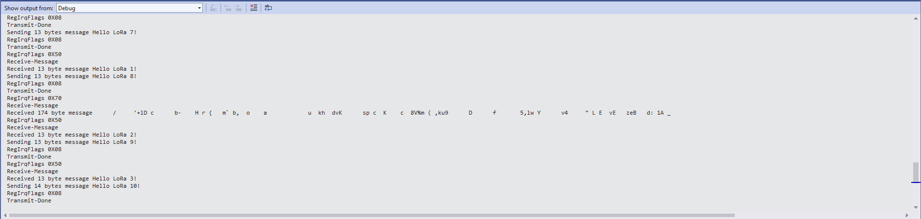
ReceiveTransmitInterrupt application output
The ReceiveTransmitInterrupt application combines the functionality TransmitInterrupt and ReceiveInterrupt programs. The key differences are the RegDioMapping1 setup and in InterruptGpioPin_ValueChanged where the TxDone & RxDone flags in the RegIrqFlags register specify how the interrupt is handled.
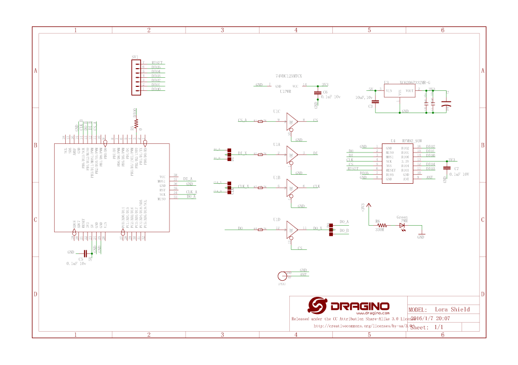
For testing nanoFramework device transmit and receive functionality I used an Arduino/Seeeduino with a Dragino LoRa Shield (running one of the Arduino-LoRa samples) as a client device. This was so I could “bootstrap” connectivity and test interoperability with other libraries/platforms.
Arduino/Netduino devices for .NET nanoFramework interoperability test-rig
I started with transmit as I was confident my Seeeduino + Dragino LoRa Shield could receive messages. The TransmitBasic application puts the device into LoRa + Sleep mode as after reset/powering up the device is in FSK/OOK, Low Frequency + Standby mode).
SX127X RegOpMode options
After loading the message to be sent into the First In First Out(FIFO) buffer, the RegOpMode-Mode is set to Transmit(TX-011), and then the RegIrqFlags register is polled until the TxDone flag is set.
SX127X ReqIrqFlags options
public static void Main()
{
  int SendCount = 0;
...
  Debug.WriteLine("devMobile.IoT.SX127x.TransmitBasic starting");

   try
   {
...
#if NETDUINO3_WIFI || ST_STM32F769I_DISCOVERY
      SX127XDevice sx127XDevice = new SX127XDevice(SpiBusId, chipSelectLine, resetPinNumber);
#endif
     Thread.Sleep(500);

     // Put device into LoRa + Standby mode
     sx127XDevice.WriteByte(0x01, 0b10000000); // RegOpMode

      // Set the frequency to 915MHz
      byte[] frequencyBytes = { 0xE4, 0xC0, 0x00 }; // RegFrMsb, RegFrMid, RegFrLsb
      sx127XDevice.WriteBytes(0x06, frequencyBytes);

      // More power PA Boost
      sx127XDevice.WriteByte(0x09, 0b10000000); // RegPaConfig

      sx127XDevice.RegisterDump();

      while (true)
      {
         sx127XDevice.WriteByte(0x0E, 0x0); // RegFifoTxBaseAddress

         // Set the Register Fifo address pointer
         sx127XDevice.WriteByte(0x0D, 0x0); // RegFifoAddrPtr

         string messageText = $"Hello LoRa from .NET nanoFramework {SendCount += 1}!";

         // load the message into the fifo
         byte[] messageBytes = UTF8Encoding.UTF8.GetBytes(messageText);
         sx127XDevice.WriteBytes(0x0, messageBytes); // RegFifo

         // Set the length of the message in the fifo
         sx127XDevice.WriteByte(0x22, (byte)messageBytes.Length); // RegPayloadLength

         Debug.WriteLine($"Sending {messageBytes.Length} bytes message {messageText}");
         // Set the mode to LoRa + Transmit
         sx127XDevice.WriteByte(0x01, 0b10000011); // RegOpMode

         // Wait until send done, no timeouts in PoC
         Debug.WriteLine("Send-wait");
         byte irqFlags = sx127XDevice.ReadByte(0x12); // RegIrqFlags
         while ((irqFlags & 0b00001000) == 0)  // wait until TxDone cleared
         {
            Thread.Sleep(10);
            irqFlags = sx127XDevice.ReadByte(0x12); // RegIrqFlags
            Debug.Write(".");
         }
         Debug.WriteLine("");
         sx127XDevice.WriteByte(0x12, 0b00001000); // clear TxDone bit
         Debug.WriteLine("Send-Done");

         Thread.Sleep(30000);
         }
      }
      catch (Exception ex)
      {
         Debug.WriteLine(ex.Message);
      }
   }
}
Transmit Basic application output
Once the TransmitBasic application was sending messages reliably I started working on the ReceiveBasic application. As the ReceiveBasic application starts up the SX127X RegOpMode has to be set to sleep/standby so the device can be configured. TOnce that is completed RegOpMode-Mode is set to RxContinuous(101), and the RegIrqFlags register is polled until the RxDone flag is set.
public static void Main()
{
...
   Debug.WriteLine("devMobile.IoT.SX127x.ReceiveBasic starting");

   try
   {
...
#if NETDUINO3_WIFI || ST_STM32F769I_DISCOVERY
      SX127XDevice sx127XDevice = new SX127XDevice(SpiBusId, chipSelectLine, resetPinNumber);
#endif
      Thread.Sleep(500);

      // Put device into LoRa + Sleep mode
      sx127XDevice.WriteByte(0x01, 0b10000000); // RegOpMode

      // Set the frequency to 915MHz
      byte[] frequencyBytes = { 0xE4, 0xC0, 0x00 }; // RegFrMsb, RegFrMid, RegFrLsb
      sx127XDevice.WriteBytes(0x06, frequencyBytes);

      sx127XDevice.WriteByte(0x0F, 0x0); // RegFifoRxBaseAddress

      sx127XDevice.WriteByte(0x01, 0b10000101); // RegOpMode set LoRa & RxContinuous

       while (true)
       {
          // Wait until a packet is received, no timeouts in PoC
         Debug.WriteLine("Receive-Wait");
         byte irqFlags = sx127XDevice.ReadByte(0x12); // RegIrqFlags
         while ((irqFlags & 0b01000000) == 0)  // wait until RxDone cleared
         {
            Thread.Sleep(100);
            irqFlags = sx127XDevice.ReadByte(0x12); // RegIrqFlags
            Debug.Write(".");
         }
         Debug.WriteLine("");
         Debug.WriteLine($"RegIrqFlags 0X{irqFlags:X2}");
         Debug.WriteLine("Receive-Message");
         byte currentFifoAddress = sx127XDevice.ReadByte(0x10); // RegFifiRxCurrent
         sx127XDevice.WriteByte(0x0d, currentFifoAddress); // RegFifoAddrPtr

         byte numberOfBytes = sx127XDevice.ReadByte(0x13); // RegRxNbBytes

         // Read the message from the FIFO
         byte[] messageBytes = sx127XDevice.ReadBytes(0x00, numberOfBytes);

         sx127XDevice.WriteByte(0x0d, 0);
         sx127XDevice.WriteByte(0x12, 0b11111111); // RegIrqFlags clear all the bits

         // Remove unprintable characters from messages
         for (int index = 0; index < messageBytes.Length; index++)
         {
            if ((messageBytes[index] < 0x20) || (messageBytes[index] > 0x7E))
            {
               messageBytes[index] = 0x20;
            }
         }

         string messageText = UTF8Encoding.UTF8.GetString(messageBytes, 0, messageBytes.Length);
         Debug.WriteLine($"Received {messageBytes.Length} byte message {messageText}");

         Debug.WriteLine("Receive-Done");
      }
    }
   catch (Exception ex)
   {
      Debug.WriteLine(ex.Message);
   }
}
Receive Basic application output
Every so often the ReceiveBasic application would display a message sent on the same frequency by a device somewhere nearby.
ReceiveBasic application messages from unknown source
I need to do some more investigation into whether writing 0b00001000 (Transmit) vs. 0b11111111(Receive) to RegIrqFlags is important.
Now that I could reliably dump all the Dragino shield registers I wanted to be able to configure the Semtech 127X device and reset it back to factory settings. A factory reset is done by strobing the SX127X reset pin.
SX127X Reset timing diagram
SX127X Reset process
To support this I added a constructor with an additional parameter for the reset General Purpose Input Output(GPIO) pin number to the SX127XDevice class. The original constructor was retained as the SX127X reset pin is not connected on the SparkFun LoRa Gateway-1-Channel (ESP32) and a limited number of other devices.
namespace devMobile.IoT.SX127x.RegisterReadAndWrite
{
using System;
using System.Diagnostics;
using System.Threading;
using System.Device.Gpio;
using System.Device.Spi;
#if ESP32_WROOM_32_LORA_1_CHANNEL
using nanoFramework.Hardware.Esp32;
#endif
public sealed class SX127XDevice
{
private const byte RegisterAddressMinimum = 0X0;
private const byte RegisterAddressMaximum = 0x42;
private const byte RegisterAddressReadMask = 0X7f;
private const byte RegisterAddressWriteMask = 0x80;
private readonly SpiDevice SX127XTransceiver;
public SX127XDevice(int busId, int chipSelectLine, int resetPin)
{
var settings = new SpiConnectionSettings(busId, chipSelectLine)
{
ClockFrequency = 1000000,
Mode = SpiMode.Mode0,// From SemTech docs pg 80 CPOL=0, CPHA=0
SharingMode = SpiSharingMode.Shared
};
SX127XTransceiver = new SpiDevice(settings);
// Factory reset pin configuration
GpioController gpioController = new GpioController();
gpioController.OpenPin(resetPin, PinMode.Output);
gpioController.Write(resetPin, PinValue.Low);
Thread.Sleep(20);
gpioController.Write(resetPin, PinValue.High);
Thread.Sleep(20);
}
public SX127XDevice(int busId, int chipSelectLine)
{
var settings = new SpiConnectionSettings(busId, chipSelectLine)
{
ClockFrequency = 1000000,
Mode = SpiMode.Mode0,// From SemTech docs pg 80 CPOL=0, CPHA=0
SharingMode = SpiSharingMode.Shared,
};
SX127XTransceiver = new SpiDevice(settings);
}
public Byte ReadByte(byte registerAddress)
{
byte[] writeBuffer = new byte[] { registerAddress &= RegisterAddressReadMask, 0x0 };
byte[] readBuffer = new byte[writeBuffer.Length];
SX127XTransceiver.TransferFullDuplex(writeBuffer, readBuffer);
return readBuffer[1];
}
public ushort ReadWord(byte address)
{
byte[] writeBuffer = new byte[] { address &= RegisterAddressReadMask, 0x0, 0x0 };
byte[] readBuffer = new byte[writeBuffer.Length];
SX127XTransceiver.TransferFullDuplex(writeBuffer, readBuffer);
return (ushort)(readBuffer[2] + (readBuffer[1] << 8));
}
public ushort ReadWordMsbLsb(byte address)
{
byte[] writeBuffer = new byte[] { address &= RegisterAddressReadMask, 0x0, 0x0 };
byte[] readBuffer = new byte[writeBuffer.Length];
SX127XTransceiver.TransferFullDuplex(writeBuffer, readBuffer);
return (ushort)((readBuffer[1] << 8) + readBuffer[2]);
}
public byte[] ReadBytes(byte address, byte length)
{
byte[] writeBuffer = new byte[length + 1];
byte[] readBuffer = new byte[writeBuffer.Length];
byte[] replyBuffer = new byte[length];
writeBuffer[0] = address &= RegisterAddressReadMask;
SX127XTransceiver.TransferFullDuplex(writeBuffer, readBuffer);
Array.Copy(readBuffer, 1, replyBuffer, 0, length);
return replyBuffer;
}
public void WriteByte(byte address, byte value)
{
byte[] writeBuffer = new byte[] { address |= RegisterAddressWriteMask, value };
byte[] readBuffer = new byte[writeBuffer.Length];
SX127XTransceiver.TransferFullDuplex(writeBuffer, readBuffer);
}
public void WriteWord(byte address, ushort value)
{
byte[] valueBytes = BitConverter.GetBytes(value);
byte[] writeBuffer = new byte[] { address |= RegisterAddressWriteMask, valueBytes[0], valueBytes[1] };
byte[] readBuffer = new byte[writeBuffer.Length];
SX127XTransceiver.TransferFullDuplex(writeBuffer, readBuffer);
}
public void WriteWordMsbLsb(byte address, ushort value)
{
byte[] valueBytes = BitConverter.GetBytes(value);
byte[] writeBuffer = new byte[] { address |= RegisterAddressWriteMask, valueBytes[1], valueBytes[0] };
byte[] readBuffer = new byte[writeBuffer.Length];
SX127XTransceiver.TransferFullDuplex(writeBuffer, readBuffer);
}
public void WriteBytes(byte address, byte[] bytes)
{
byte[] writeBuffer = new byte[1 + bytes.Length];
byte[] readBuffer = new byte[writeBuffer.Length];
Array.Copy(bytes, 0, writeBuffer, 1, bytes.Length);
writeBuffer[0] = address |= RegisterAddressWriteMask;
SX127XTransceiver.TransferFullDuplex(writeBuffer, readBuffer);
}
public void RegisterDump()
{
Debug.WriteLine("Register dump");
for (byte registerIndex = RegisterAddressMinimum; registerIndex <= RegisterAddressMaximum; registerIndex++)
{
byte registerValue = this.ReadByte(registerIndex);
Debug.WriteLine($"Register 0x{registerIndex:x2} - Value 0X{registerValue:x2}");
}
Debug.WriteLine("");
}
}
public class Program
{
#if ESP32_WROOM_32_LORA_1_CHANNEL
private const int SpiBusId = 1;
#endif
#if NETDUINO3_WIFI
private const int SpiBusId = 2;
#endif
#if ST_STM32F769I_DISCOVERY
private const int SpiBusId = 2;
#endif
public static void Main()
{
byte[] frequencyBytes;
#if ESP32_WROOM_32_LORA_1_CHANNEL // No reset line for this device as it isn't connected on SX127X
int chipSelectLine = Gpio.IO16;
#endif
#if NETDUINO3_WIFI
// Arduino D10->PB10
int chipSelectLine = PinNumber('B', 10);
// Arduino D9->PE5
int resetPinNumber = PinNumber('E', 5);
#endif
#if ST_STM32F769I_DISCOVERY
// Arduino D10->PA11
int chipSelectLine = PinNumber('A', 11);
// Arduino D9->PH6
int resetPinNumber = PinNumber('H', 6);
#endif
Debug.WriteLine("devMobile.IoT.SX127x.RegisterReadAndWrite starting");
try
{
#if ESP32_WROOM_32_LORA_1_CHANNEL
Configuration.SetPinFunction(Gpio.IO12, DeviceFunction.SPI1_MISO);
Configuration.SetPinFunction(Gpio.IO13, DeviceFunction.SPI1_MOSI);
Configuration.SetPinFunction(Gpio.IO14, DeviceFunction.SPI1_CLOCK);
SX127XDevice sx127XDevice = new SX127XDevice(SpiBusId, chipSelectLine);
#endif
#if NETDUINO3_WIFI || ST_STM32F769I_DISCOVERY
SX127XDevice sx127XDevice = new SX127XDevice(SpiBusId, chipSelectLine, resetPinNumber);
#endif
Thread.Sleep(500);
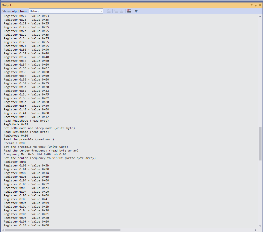
sx127XDevice.RegisterDump();
while (true)
{
Debug.WriteLine("Read RegOpMode (read byte)");
Byte regOpMode1 = sx127XDevice.ReadByte(0x1);
Debug.WriteLine($"RegOpMode 0x{regOpMode1:x2}");
Debug.WriteLine("Set LoRa mode and sleep mode (write byte)");
sx127XDevice.WriteByte(0x01, 0b10000000);
Debug.WriteLine("Read RegOpMode (read byte)");
Byte regOpMode2 = sx127XDevice.ReadByte(0x1);
Debug.WriteLine($"RegOpMode 0x{regOpMode2:x2}");
Debug.WriteLine("Read the preamble (read word)");
ushort preamble = sx127XDevice.ReadWord(0x20);
Debug.WriteLine($"Preamble 0x{preamble:x2}");
Console.WriteLine("Read the preamble (read word)"); // Should be 0x08
preamble = sx127XDevice.ReadWordMsbLsb(0x20);
Debug.WriteLine($"Preamble 0x{preamble:x2}");
Debug.WriteLine("Read the centre frequency (read byte array)");
frequencyBytes = sx127XDevice.ReadBytes(0x06, 3);
Debug.WriteLine($"Frequency Msb 0x{frequencyBytes[0]:x2} Mid 0x{frequencyBytes[1]:x2} Lsb 0x{frequencyBytes[2]:x2}");
Debug.WriteLine("Set the centre frequency to 915MHz (write byte array)");
byte[] frequencyWriteBytes = { 0xE4, 0xC0, 0x00 };
sx127XDevice.WriteBytes(0x06, frequencyWriteBytes);
Debug.WriteLine("Read the centre frequency (read byte array)");
frequencyBytes = sx127XDevice.ReadBytes(0x06, 3);
Debug.WriteLine($"Frequency Msb 0x{frequencyBytes[0]:x2} Mid 0x{frequencyBytes[1]:x2} Lsb 0x{frequencyBytes[2]:x2}");
sx127XDevice.RegisterDump();
Thread.Sleep(30000);
}
}
catch (Exception ex)
{
Debug.WriteLine(ex.Message);
}
}
#if NETDUINO3_WIFI || ST_STM32F769I_DISCOVERY
static int PinNumber(char port, byte pin)
{
if (port < 'A' || port > 'J')
throw new ArgumentException();
return ((port - 'A') * 16) + pin;
}
#endif
}
}
The PinNumber helper is more user friendly that the raw numbers and is “inspired” by sample .NET nanoFramework General Purpose Input Output(GPIO) sample code.
Each method was tested by read/writing suitable register(s) in the device configuration (Needed to set it into LoRa mode first).
The next step is to extract the Serial Peripheral Interface(SPI) register access functionality into a module and configure the bare minimum of settings required to get the SX127X to receive and transmit messages.
All this madness started because I wasn’t confident the frequency calculation of the Emmellsoft Dragino.Lora code was correct. Over the last couple of years I have also found bugs in my Transmit Power, InvertIQ RX/TX with many others yet to be discovered.
I then fixed all the breaking changes (For the initial versions I have not updated the code to use SpanByte etc.).
public Rfm9XDevice(int spiBusId, int chipSelectPin, int resetPin, int interruptPin)
{
   //...

   // Interrupt pin for RX message & TX done notification
   InterruptGpioPin = gpioController.OpenPin(interruptPin);
   InterruptGpioPin.SetPinMode(PinMode.Input);

   InterruptGpioPin.ValueChanged += InterruptGpioPin_ValueChanged;
}

private void InterruptGpioPin_ValueChanged(object sender, PinValueChangedEventArgs e)
{
   if (e.ChangeType != PinEventTypes.Rising)
   {
      return;
   }

   byte irqFlags = this.RegisterReadByte(0x12); // RegIrqFlags
   //...
}
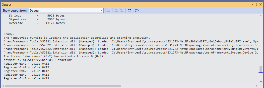
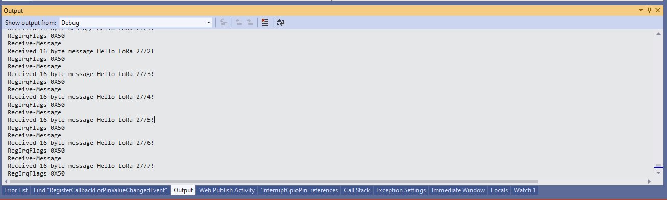
While “soak testing” the ReceiveInterrupt application I noticed that sometimes when I started the application interrupts were not processed or processing stopped after a while.
Visual Studio Debugger output showing intermittent calling of InterruptGpioPin_ValueChanged
The arduino-LoRa library LoRaDuplex sample is the basis for the last in this series of posts. The LoRaDuplex sample implements a basic protocol for addressed messages. The message payload starts with the destination address(byte), source address(byte), message counter(byte), payload length(byte), and then the payload(array of bytes).
LoRaDuplex
The sample code has configuration settings for the local address and destination (address).
#include <SPI.h>              // include libraries
#include <LoRa.h>

const int csPin = 10;          // LoRa radio chip select
const int resetPin = 9;       // LoRa radio reset
const int irqPin = 2;         // change for your board; must be a hardware interrupt pin

String outgoing;              // outgoing message

byte msgCount = 0;            // count of outgoing messages
byte localAddress = 0xAA;     // address of this device
byte destination = 0x0;      // destination to send to
long lastSendTime = 0;        // last send time
int interval = 2000;          // interval between sends

void setup() {
  Serial.begin(9600);                   // initialize serial
  while (!Serial);

  Serial.println("LoRa Duplex");

  // override the default CS, reset, and IRQ pins (optional)
  LoRa.setPins(csPin, resetPin, irqPin);// set CS, reset, IRQ pin

  if (!LoRa.begin(915E6)) {             // initialize ratio at 915 MHz
    Serial.println("LoRa init failed. Check your connections.");
    while (true);                       // if failed, do nothing
  }

  LoRa.enableCrc();

  Serial.println("LoRa init succeeded.");
}

void loop() {
  if (millis() - lastSendTime > interval) {
    String message = "HeLoRa World!";   // send a message
    sendMessage(message);
    Serial.println("Sending " + message);
    lastSendTime = millis();            // timestamp the message
    interval = random(2000) + 29000;    // 2-3 seconds
  }

  // parse for a packet, and call onReceive with the result:
  onReceive(LoRa.parsePacket());
}

void sendMessage(String outgoing) {
  LoRa.beginPacket();                   // start packet
  LoRa.write(destination);              // add destination address
  LoRa.write(localAddress);             // add sender address
  LoRa.write(msgCount);                 // add message ID
  LoRa.write(outgoing.length());        // add payload length
  LoRa.print(outgoing);                 // add payload
  LoRa.endPacket();                     // finish packet and send it
  msgCount++;                           // increment message ID
}

void onReceive(int packetSize) {
  if (packetSize == 0) return;          // if there's no packet, return

  // read packet header bytes:
  int recipient = LoRa.read();          // recipient address
  byte sender = LoRa.read();            // sender address
  byte incomingMsgId = LoRa.read();     // incoming msg ID
  byte incomingLength = LoRa.read();    // incoming msg length

  String incoming = "";

  while (LoRa.available()) {
    incoming += (char)LoRa.read();
  }

  if (incomingLength != incoming.length()) {   // check length for error
    Serial.println("error: message length does not match length");
    return;                             // skip rest of function
  }

  // if the recipient isn't this device or broadcast,
  if (recipient != localAddress && recipient != 0xFF) {
    Serial.println("This message is not for me.");
    return;                             // skip rest of function
  }

  // if message is for this device, or broadcast, print details:
  Serial.println("Received from: 0x" + String(sender, HEX));
  Serial.println("Sent to: 0x" + String(recipient, HEX));
  Serial.println("Message ID: " + String(incomingMsgId));
  Serial.println("Message length: " + String(incomingLength));
  Serial.println("Message: " + incoming);
  Serial.println("RSSI: " + String(LoRa.packetRssi()));
  Serial.println("Snr: " + String(LoRa.packetSnr()));
  Serial.println();
}
Arduino Monitor displaying information about the messages sent and received by the Duplex sample
static void Main(string[] args)
{
	int messageCount = 1;

	sX127XDevice.Initialise(
			SX127XDevice.RegOpModeMode.ReceiveContinuous,
			915000000.0,
			powerAmplifier: SX127XDevice.PowerAmplifier.PABoost,
#if LORA_SENDER // From the Arduino point of view
			rxDoneignoreIfCrcMissing: false
#endif
#if LORA_RECEIVER // From the Arduino point of view, don't actually need this as already inverted
			invertIQTX: true
#endif

#if LORA_SET_SYNCWORD
			syncWord: 0xF3,
			invertIQTX: true,
			rxDoneignoreIfCrcMissing: false
#endif
#if LORA_SET_SPREAD
			spreadingFactor: SX127XDevice.RegModemConfig2SpreadingFactor._256ChipsPerSymbol,
			invertIQTX: true,
			rxDoneignoreIfCrcMissing: false
#endif
#if LORA_SIMPLE_NODE // From the Arduino point of view
			invertIQTX: false,
			rxDoneignoreIfCrcMissing: false
#endif
#if LORA_SIMPLE_GATEWAY // From the Arduino point of view
			invertIQRX: true,
			rxDoneignoreIfCrcMissing: false
#endif
#if LORA_DUPLEX
			rxPayloadCrcOn: true
#endif
			);

#if DEBUG
	sX127XDevice.RegisterDump();
#endif

#if !LORA_RECEIVER
	sX127XDevice.OnReceive += SX127XDevice_OnReceive;
	sX127XDevice.Receive();
#endif
#if !LORA_SENDER
	sX127XDevice.OnTransmit += SX127XDevice_OnTransmit;
#endif

#if LORA_SENDER
	Thread.Sleep(-1);
#else
	Thread.Sleep(5000);
#endif

	while (true)
	{
		string messageText = "Hello LoRa from .NET Core! " + messageCount.ToString();

#if LORA_DUPLEX
		byte[] messageBytes = new byte[messageText.Length+4];

		messageBytes[0] = 0xaa;
		messageBytes[1] = 0x00;
		messageBytes[2] = (byte)messageCount;
		messageBytes[3] = (byte)messageText.Length;

		Array.Copy(UTF8Encoding.UTF8.GetBytes(messageText), 0, messageBytes, 4, messageBytes[3]);

		Console.WriteLine($"{DateTime.Now:HH:mm:ss}-TX to 0x{messageBytes[0]:X2} from 0x{messageBytes[1]:X2} count {messageBytes[2]} length {messageBytes[3]} \"{messageText}\"");
#else
		byte[] messageBytes = UTF8Encoding.UTF8.GetBytes(messageText);

		Console.WriteLine($"{DateTime.Now:HH:mm:ss}- Length {messageBytes.Length} \"{messageText}\"");
#endif

		messageCount += 1;

		sX127XDevice.Send(messageBytes);

		Thread.Sleep(10000);
	}
}

private static void SX127XDevice_OnReceive(object sender, SX127XDevice.OnDataReceivedEventArgs e)
{
	string messageText;

#if LORA_DUPLEX
	if ((e.Data[0] != 0x00) && (e.Data[0] != 0xFF))
	{
#if DEBUG
		Console.WriteLine($"{DateTime.UtcNow:hh:mm:ss}-RX to 0x{e.Data[0]:X2} from 0x{e.Data[1]:X2} invalid address");
#endif
		return;
	}

	// check payload not to long/short
	if  ((e.Data[3] + 4) != e.Data.Length)
	{
		Console.WriteLine($"{DateTime.UtcNow:hh:mm:ss}-RX Invalid payload");

		return;
	}

	try
	{
		messageText = UTF8Encoding.UTF8.GetString(e.Data, 4, e.Data[3]);

		Console.WriteLine($"{DateTime.Now:HH:mm:ss}-RX to 0x{e.Data[0]:X2} from 0x{e.Data[1]:X2} count {e.Data[2]} length {e.Data[3]} \"{messageText}\" snr {e.PacketSnr:0.0} packet rssi {e.PacketRssi}dBm rssi {e.Rssi}dBm ");
	}
	catch (Exception ex)
	{
		Console.WriteLine(ex.Message);
	}
#else
	try
	{
		messageText = UTF8Encoding.UTF8.GetString(e.Data);

		Console.WriteLine($"{DateTime.Now:HH:mm:ss}-RX length {e.Data.Length} \"{messageText}\" snr {e.PacketSnr:0.0} packet rssi {e.PacketRssi}dBm rssi {e.Rssi}dBm ");
	}
	catch (Exception ex)
	{
		Console.WriteLine(ex.Message);
	}
#endif
}
The inbound messages have to have a valid Cyclic Redundancy Check(CRC) and I ignore messages with an invalid payload length. The message protocol is insecure (but fine for demos) as the messages are sent as “plain text”, and the message headers/payload can be tampered with.
Summary
While testing the LoRaDuplex sample I found a problem with how my code managed the invertIQRX & invertIQTX flags in RegInvertIQ. I noticed the even though I was setting the InvertIQRX(bit6) and invertIQTX(bit0) flags correctly messages weren’t getting delivered.
Semtech SX127X data sheet RegInvertQ and RegInvertQ2 documetnation
After looking at my code I realised I wasn’t configuring the RegInvertIQ properly because bits 1-5 were getting set to 0x0 (initially I had byte regInvertIQValue = 0) rather than 0x13(regInvertIQValue = RegInvertIdDefault)
int messageCount = 1;

sX127XDevice.Initialise(
		SX127XDevice.RegOpModeMode.ReceiveContinuous,
		915000000.0,
		powerAmplifier: SX127XDevice.PowerAmplifier.PABoost,
		// outputPower: 5, outputPower: 20, outputPower:23,
		//powerAmplifier: SX127XDevice.PowerAmplifier.Rfo,
		//outputPower:-1, outputPower: 14,
#if LORA_SENDER // From the Arduino point of view
		rxDoneignoreIfCrcMissing: false
#endif
#if LORA_RECEIVER // From the Arduino point of view, don't actually need this as already inverted
		invertIQTX: true
#endif

#if LORA_SET_SYNCWORD
		syncWord: 0xF3,
		invertIQTX: true,
		rxDoneignoreIfCrcMissing: false
#endif
#if LORA_SET_SPREAD
		spreadingFactor: SX127XDevice.RegModemConfig2SpreadingFactor._256ChipsPerSymbol,
		invertIQTX: true,
		rxDoneignoreIfCrcMissing: false
#endif
#if LORA_SIMPLE_NODE // From the Arduino point of view
		invertIQTX: false,
		rxDoneignoreIfCrcMissing: false
#endif
#if LORA_SIMPLE_GATEWAY // From the Arduino point of view
		invertIQRX: true,
		rxDoneignoreIfCrcMissing: false
#endif
		);

#if DEBUG
		sX127XDevice.RegisterDump();
#endif

#if !LORA_RECEIVER
		sX127XDevice.OnReceive += SX127XDevice_OnReceive;
		sX127XDevice.Receive();
#endif
#if !LORA_SENDER
		sX127XDevice.OnTransmit += SX127XDevice_OnTransmit;
#endif

#if LORA_SENDER
		Thread.Sleep(-1);
#else
		Thread.Sleep(5000);
#endif

		while (true)
		{
			string messageText = "Hello LoRa from .NET Core! " + messageCount.ToString();

			byte[] messageBytes = UTF8Encoding.UTF8.GetBytes(messageText);

			Console.WriteLine($"{DateTime.Now:HH:mm:ss}- Length {messageBytes.Length} \"{messageText}\"");

			messageCount += 1;

			sX127XDevice.Send(messageBytes);

			Thread.Sleep(10000);
		}
	}
Summary
While testing the LoRaReceiver sample I found a problem with how my code managed the transmit power by accidentally commenting out the “paBoost: true” parameter of the initialise method. When I did this the Seeeduino V4.2 and Dragino Shield stopped receiving messages.
I had assumed a user could configure the the output power using the initialise method but that was difficult/possible. After some digging I found that I needed to use RegPAConfigPADac and PABoost (I need to find a device which uses RFO for testing). So I removed several of the configuration parameters from the Intialise method and replaced them with one called outputPower. I then re-read the SX127X data sheet and had a look at some other libraries.
void RH_RF95::setTxPower(int8_t power, bool useRFO)
{
    // Sigh, different behaviours depending on whther the module use PA_BOOST or the RFO pin
    // for the transmitter output
    if (useRFO)
    {
	if (power > 14)
	    power = 14;
	if (power < -1)
	    power = -1;
	spiWrite(RH_RF95_REG_09_PA_CONFIG, RH_RF95_MAX_POWER | (power + 1));
    }
    else
    {
	if (power > 23)
	    power = 23;
	if (power < 5)
	    power = 5;

	// For RH_RF95_PA_DAC_ENABLE, manual says '+20dBm on PA_BOOST when OutputPower=0xf'
	// RH_RF95_PA_DAC_ENABLE actually adds about 3dBm to all power levels. We will us it
	// for 21, 22 and 23dBm
	if (power > 20)
	{
	    spiWrite(RH_RF95_REG_4D_PA_DAC, RH_RF95_PA_DAC_ENABLE);
	    power -= 3;
	}
	else
	{
	    spiWrite(RH_RF95_REG_4D_PA_DAC, RH_RF95_PA_DAC_DISABLE);
	}

	// RFM95/96/97/98 does not have RFO pins connected to anything. Only PA_BOOST
	// pin is connected, so must use PA_BOOST
	// Pout = 2 + OutputPower.
	// The documentation is pretty confusing on this topic: PaSelect says the max power is 20dBm,
	// but OutputPower claims it would be 17dBm.
	// My measurements show 20dBm is correct
	spiWrite(RH_RF95_REG_09_PA_CONFIG, RH_RF95_PA_SELECT | (power-5));
    }
}
The LoRa Shield Arduino library has two methods setPower(char p) and setPowerNum(uint8_t pow)
/*
 Function: Sets the signal power indicated as input to the module.
 Returns: Integer that determines if there has been any error
   state = 2  --> The command has not been executed
   state = 1  --> There has been an error while executing the command
   state = 0  --> The command has been executed with no errors
   state = -1 --> Forbidden command for this protocol
 Parameters:
   pow: power option to set in configuration. The input value range is from
   0 to 14 dBm.
*/
int8_t SX1278::setPowerNum(uint8_t pow)
{
  byte st0;
  int8_t state = 2;
  byte value = 0x00;

  #if (SX1278_debug_mode > 1)
	  Serial.println();
	  Serial.println(F("Starting 'setPower'"));
  #endif

  st0 = readRegister(REG_OP_MODE);	  // Save the previous status
  if( _modem == LORA )
  { // LoRa Stdby mode to write in registers
	  writeRegister(REG_OP_MODE, LORA_STANDBY_MODE);
  }
  else
  { // FSK Stdby mode to write in registers
	  writeRegister(REG_OP_MODE, FSK_STANDBY_MODE);
  }

  if ( (pow >= 2) && (pow <= 20) )
  { // Pout= 17-(15-OutputPower) = OutputPower+2
	  if ( pow <= 17 ) {
		writeRegister(REG_PA_DAC, 0x84);
	  	pow = pow - 2;
	  } else { // Power > 17dbm -> Power = 20dbm
		writeRegister(REG_PA_DAC, 0x87);
		pow = 15;
	  }
	  _power = pow;
  }
  else
  {
	  state = -1;
	  #if (SX1278_debug_mode > 1)
		  Serial.println(F("## Power value is not valid ##"));
		  Serial.println();
	  #endif
  }

  writeRegister(REG_PA_CONFIG, _power);	// Setting output power value
  value = readRegister(REG_PA_CONFIG);

  if( value == _power )
  {
	  state = 0;
	  #if (SX1278_debug_mode > 1)
		  Serial.println(F("## Output power has been successfully set ##"));
		  Serial.println();
	  #endif
  }
  else
  {
	  state = 1;
  }

  writeRegister(REG_OP_MODE, st0);	// Getting back to previous status
  return state;
}
The SEMTECH library(V2.1.0) manages sleeping the device, reading the existing configuration and updating it as required which was a bit more functionality that I wanted.
All the of the examples I looked at were different and some had manual tweaks, others I have not included were just wrong. I have based my beta version on a hybrid of the Arduino-LoRa, RadioHead and Semtech libraries. I need to test my code and confirm that I have the limits and offsets correct for the PABoost and RFO modes.
// RegPaDac more power
[Flags]
public enum RegPaDac
{
	Normal = 0b01010100,
	Boost = 0b01010111,
}
private const byte RegPaDacPABoostThreshold = 20;
// Validate the OutputPower
if (powerAmplifier == PowerAmplifier.Rfo)
{
	if ((outputPower < OutputPowerRfoMin) || (outputPower > OutputPowerRfoMax))
	{
		throw new ArgumentException($"outputPower must be between {OutputPowerRfoMin} and {OutputPowerRfoMax}", nameof(outputPower));
	}
}
if (powerAmplifier == PowerAmplifier.PABoost)
{
	if ((outputPower < OutputPowerPABoostMin) || (outputPower > OutputPowerPABoostMax))
	{
		throw new ArgumentException($"outputPower must be between {OutputPowerPABoostMin} and {OutputPowerPABoostMax}", nameof(outputPower));
	}
}

if (( powerAmplifier != PowerAmplifierDefault) || (outputPower != OutputPowerDefault))
{
	byte regPAConfigValue = RegPAConfigMaxPowerMax;

	if (powerAmplifier == PowerAmplifier.Rfo)
	{
		regPAConfigValue |= RegPAConfigPASelectRfo;

		regPAConfigValue |= (byte)(outputPower + 1);

		this.WriteByte((byte)Registers.RegPAConfig, regPAConfigValue);
	}

	if (powerAmplifier == PowerAmplifier.PABoost)
	{
		regPAConfigValue |= RegPAConfigPASelectPABoost;

		if (outputPower > RegPaDacPABoostThreshold)
		{
			this.WriteByte((byte)Registers.RegPaDac, (byte)RegPaDac.Boost);

			regPAConfigValue |= (byte)(outputPower - 8);

			this.WriteByte((byte)Registers.RegPAConfig, regPAConfigValue);
		}
		else
		{
			this.WriteByte((byte)Registers.RegPaDac, (byte)RegPaDac.Normal);

			regPAConfigValue |= (byte)(outputPower - 5);

			this.WriteByte((byte)Registers.RegPAConfig, regPAConfigValue);
		}
	}
}
The arduino-LoRa library comes with a number of samples showing how to use its functionality. The LoRaSender and LoRaReceiver samples show the bare minimum of code required to send and receive messages.
LoRaSender
This sample uses all default settings except for frequency
static void Main(string[] args)
{
	int messageCount = 1;

	sX127XDevice.Initialise(
			SX127XDevice.RegOpModeMode.ReceiveContinuous,
			915000000.0,
			powerAmplifier: SX127XDevice.PowerAmplifier.PABoost,
#if LORA_SENDER // From the Arduino point of view
			rxDoneignoreIfCrcMissing: false
#endif
#if LORA_RECEIVER // From the Arduino point of view, don't actually need this as already inverted
			invertIQTX: true
#endif

#if LORA_SET_SYNCWORD
			syncWord: 0xF3,
			invertIQTX: true,
			rxDoneignoreIfCrcMissing: false
#endif
#if LORA_SET_SPREAD
			spreadingFactor: SX127XDevice.RegModemConfig2SpreadingFactor._256ChipsPerSymbol,
			invertIQTX: true,
			rxDoneignoreIfCrcMissing: false
#endif
	);

#if DEBUG
	sX127XDevice.RegisterDump();
#endif

#if LORA_SENDER
	sX127XDevice.OnReceive += SX127XDevice_OnReceive;
	sX127XDevice.Receive();
#endif
#if LORA_RECEIVER
	sX127XDevice.OnTransmit += SX127XDevice_OnTransmit;
#endif

#if LORA_SENDER
	Thread.Sleep(-1);
#else
	Thread.Sleep(5000);
#endif

	while (true)
	{
		string messageText = "Hello LoRa from .NET Core! " + messageCount.ToString();

		byte[] messageBytes = UTF8Encoding.UTF8.GetBytes(messageText);

		Console.WriteLine($"{DateTime.Now:HH:mm:ss}- Length {messageBytes.Length} \"{messageText}\"");

		sX127XDevice.Send(messageBytes);

		messageCount += 1;

		Thread.Sleep(10000);
	}
}
Summary
While testing the LoRaReceiver sample I found a problem with how my code managed the RegOpMode register LoRa status value. In previous versions of the code I used RegOpModeModeDefault to manage status when the ProcessTxDone(byte IrqFlags) method completed and Receive() was called.
I had assumed that that the device would always be set with SetMode(RegOpModeModeDefault) but RegOpModeModeDefault was always RegOpModeMode.Sleep.