Random wanderings through Microsoft Azure esp. PaaS plumbing, the IoT bits, AI on Micro controllers, AI on Edge Devices, .NET nanoFramework, .NET Core on *nix and ML.NET+ONNX
I wanted the RAK811 LPWAN Evaluation Board(EVB) -AS923 to work with selection of my Arduino and nanoFramework devices. The first decision was which of the hardware serial port (D0,D1) or the software serial port (D10,D11) should be connected to P1?
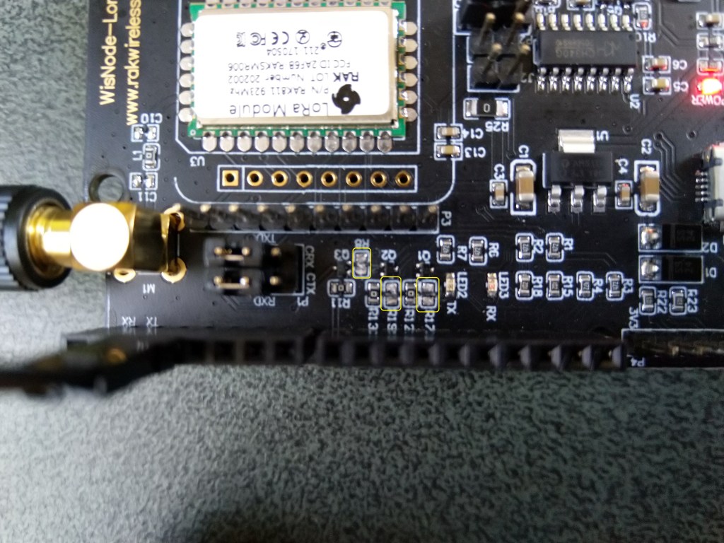
To use the EVB with my STM32F691DISCOVERY board running the nanoFramework (COM5 on the hardware serial port pins D0,D1) I removed R17&R19.
After some tinkering, I found that R8 which is connected to the RAK811 module reset had to be cut as well for the shield to work on my Arduino Uno R3 and STM32F691DISCOVERY devices.
RAK811 EVB with R17,R19 & R8 cut
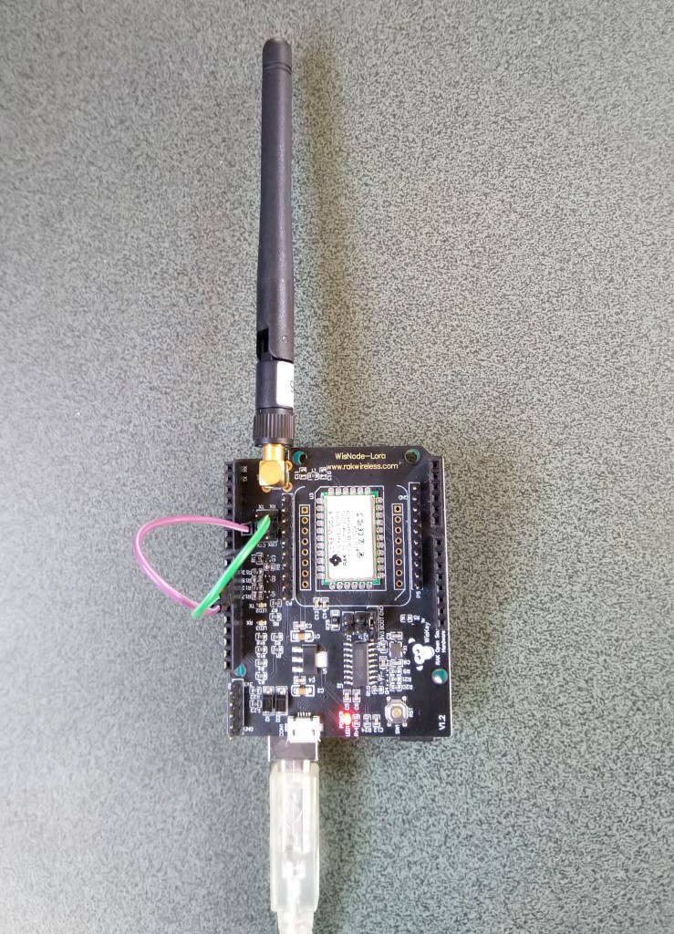
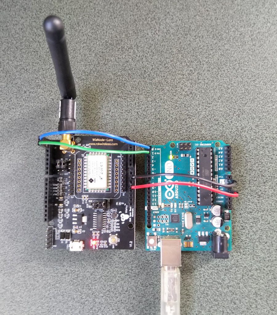
I can still run the Arduino Uno R3 and RAK811 EVB in the original configuration with a couple of jumper leads
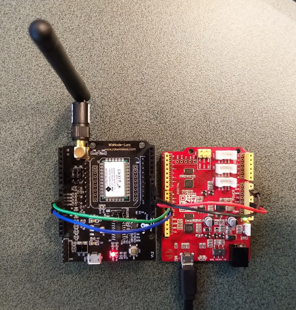
RAK811 on Arduino with Serial connected to D10,D1 a SoftwareSerial port
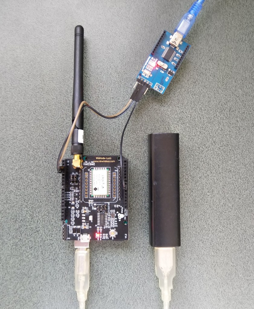
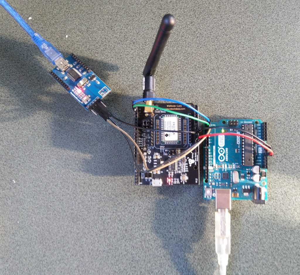
For devices where I needed D10,D11 for a Serial Peripheral Interface(SPI) I could use an FTDI board and a couple of other pins (in this case D2,D3) for serial logging.
RAK811 on Arduino with Serial connected to D2,D2 a SoftwareSerial port
After debugging some code I also replaced the small jumpers on P1 with a couple of jumper leads so it was less fiddly to swap from downloading to debugging.
Just over a week ago I purchased a RAK811 LPWAN Evaluation Board -AS923 and now I want to trial it with selection of devices and configurations.
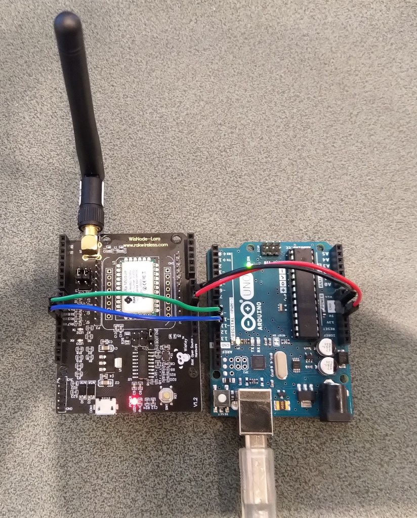
Initially I didn’t want to modify the shield by removing resistors as I only have one, and I’m not certain what device(s) it will be used with. The initial hardware configuration required jumpers for the serial port, ground and 5V power.
Arduino Uno R3 and RAK811 LPWAN Evaluation board 5V config
After looking at the schematic it should be possible to use the shield with a 3v3 device.
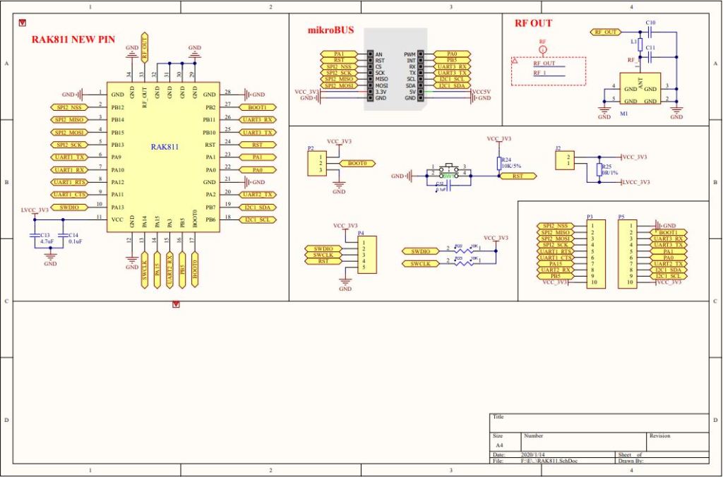
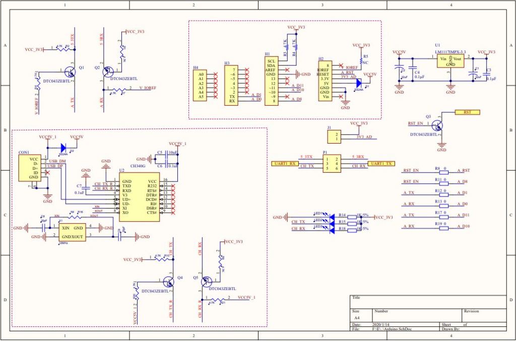
RAK 811 EVB schematic pg1RAK 811 EVB schematic pg2
I confirmed this with a Seeeduino V4.2 devices set to 3v3, by putting a jumper on J1 and shifting the jumper wire from the 5V to the 3V3 pin.
Seeeduino V4 and RAK811 LPWAN Evaluation board 3V3 config
The next step was to see how I could get the RAK shield working on other devices without jumpers. On Arduino Uno R3 devices D0&D1 are the hardware(HW) serial port which are used for uploading sketches, and diagnostic logging.
The shield also connects the module serial port to D0&D1 to D10&D11, so by removing R17&R19 the shield should work on a device This would also allow the use of the Serial Peripheral Interface(SPI) port for other applications.
Using the HW Serial port but without any logging.
Unplugging the jumpers to upload was painful but the lack of logging made it really hard to debug my code.
To get around this I configured a SoftwareSerial port on D2&D3 for logging.
/********************************************************
 * This demo is only supported after RUI firmware version 3.0.0.13.X on RAK811
 * Master Board Uart Receive buffer size at least 128 bytes.
 ********************************************************/
//#define SERIAL_BUFFER_SIZE 128
//#define SERIAL_TX_BUFFER_SIZE 64
//#define SERIAL_RX_BUFFER_SIZE 128
//#define _SS_MAX_RX_BUFF 128
#include "RAK811.h"
#include "SoftwareSerial.h"
#define WORK_MODE LoRaWAN   //  LoRaWAN or LoRaP2P
#define JOIN_MODE OTAA    //  OTAA or ABP
#if JOIN_MODE == OTAA
String DevEui = "..."; // From TTN
String AppEui = "...";
String AppKey = "...";
#else JOIN_MODE == ABP
String NwkSKey = "...";
String AppSKey = "...";
String DevAddr = "...";
#endif

#define TXpin 3   // Set the virtual serial port pins
#define RXpin 2

SoftwareSerial DebugSerial(RXpin,TXpin); // Declare a virtual serial port for debugging
#define ATSerial Serial

char buffer[]= "48656C6C6F20776F726C6435";

bool InitLoRaWAN(void);
RAK811 RAKLoRa(ATSerial,DebugSerial);

void setup() {
  DebugSerial.begin(19200);
  DebugSerial.println(F("Starting"));
  while(DebugSerial.available())
  {
    DebugSerial.read();
  }

  ATSerial.begin(9600); //set ATSerial baudrate:This baud rate has to be consistent with  the baud rate of the WisNode device.
  while(ATSerial.available())
  {
    ATSerial.read();
  }

  if(!RAKLoRa.rk_setWorkingMode(0))  //set WisNode work_mode to LoRaWAN.
  {
    DebugSerial.println(F("set work_mode failed, please reset module."));
    while(1);
  }

  RAKLoRa.rk_getVersion();  //get RAK811 firmware version
  DebugSerial.println(RAKLoRa.rk_recvData());  //print version number

  DebugSerial.println(F("Start init RAK811 parameters..."));

  if (!InitLoRaWAN())  //init LoRaWAN
  {
    DebugSerial.println(F("Init error,please reset module."));
    while(1);
  }

  DebugSerial.println(F("Start to join LoRaWAN..."));
  while(!RAKLoRa.rk_joinLoRaNetwork(60))  //Joining LoRaNetwork timeout 60s
  {
    DebugSerial.println();
    DebugSerial.println(F("Rejoin again after 5s..."));
    delay(5000);
  }
  DebugSerial.println(F("Join LoRaWAN success"));

  if(!RAKLoRa.rk_isConfirm(0))  //set LoRa data send package type:0->unconfirm, 1->confirm
  {
    DebugSerial.println(F("LoRa data send package set error,please reset module."));
    while(1);
  }
}

bool InitLoRaWAN(void)
{
  if(RAKLoRa.rk_setJoinMode(JOIN_MODE))  //set join_mode:OTAA
  {
    if(RAKLoRa.rk_setRegion(0))  //set region EU868
    {
      if (RAKLoRa.rk_initOTAA(DevEui, AppEui, AppKey))
      {
        DebugSerial.println(F("RAK811 init OK!"));
        return true;
      }
    }
  }
  return false;
}

void loop()
{
  DebugSerial.println(F("Start send data..."));
  if (RAKLoRa.rk_sendData(1, buffer))
  {
    //for (unsigned long start = millis(); millis() - start < 300000L;)
    for (unsigned long start = millis(); millis() - start < 10000L;)
    {
      String ret = RAKLoRa.rk_recvData();
      if(ret != NULL)
      {
        DebugSerial.println("ret != NULL");
        DebugSerial.println(ret);
      }
      if((ret.indexOf("OK")>0)||(ret.indexOf("ERROR")>0))
      {
        DebugSerial.println(F("Go to Sleep."));
        RAKLoRa.rk_sleep(1);  //Set RAK811 enter sleep mode
        delay(10000);  //delay 10s
        RAKLoRa.rk_sleep(0);  //Wakeup RAK811 from sleep mode
        break;
      }
    }
  }
}
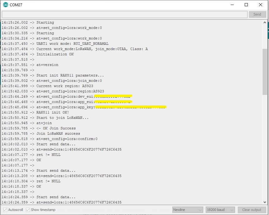
I used an FTDI module I had lying around to connect the diagnostic logging serial port on the test rig to my development box.
Using the HW Serial port but with logging.
Now I only had to unplug the jumpers for D0&D1 and change ports in the Arduino IDE. One port for debugging the other for downloading.
Depending on the application I may remove R8 so I can manually reset the shield.
I increased delay between readings to 10sec and reduced the baud rate of the serial logging to 9600baud.
/*
  This test code is write for Arduino AVR Series(UNO, Leonardo, Mega)
  If you want to use with LinkIt ONE, please connect the module to D0/1 and modify:

  // #include <SoftwareSerial.h>
  // SoftwareSerial s_serial(2, 3);      // TX, RX

  #define sensor Serial1
*/


#include <SoftwareSerial.h>
SoftwareSerial s_serial(2, 3);      // TX, RX

#define sensor s_serial

const unsigned char cmd_get_sensor[] =
{
    0xff, 0x01, 0x86, 0x00, 0x00,
    0x00, 0x00, 0x00, 0x79
};

unsigned char dataRevice[9];
int temperature;
int CO2PPM;

void setup()
{
    sensor.begin(9600);
    Serial.begin(9600);
    Serial.println("get a 'g', begin to read from sensor!");
    Serial.println("********************************************************");
    Serial.println();
}

void loop()
{
    if(dataRecieve())
    {
        Serial.print("Temperature: ");
        Serial.print(temperature);
        Serial.print("  CO2: ");
        Serial.print(CO2PPM);
        Serial.println("");
    }
    delay(10000);
}

bool dataRecieve(void)
{
    byte data[9];
    int i = 0;

    //transmit command data
    for(i=0; i<sizeof(cmd_get_sensor); i++)
    {
        sensor.write(cmd_get_sensor[i]);
    }
    delay(10);
    //begin reveiceing data
    if(sensor.available())
    {
        while(sensor.available())
        {
            for(int i=0;i<9; i++)
            {
                data[i] = sensor.read();
            }
        }
    }

    for(int j=0; j<9; j++)
    {
        Serial.print(data[j]);
        Serial.print(" ");
    }
    Serial.println("");

    if((i != 9) || (1 + (0xFF ^ (byte)(data[1] + data[2] + data[3] + data[4] + data[5] + data[6] + data[7]))) != data[8])
    {
        return false;
    }

    CO2PPM = (int)data[2] * 256 + (int)data[3];
    temperature = (int)data[4] - 40;

    return true;
}
The debug output wasn’t too promising there weren’t any C02 parts per million (ppm) values and the response payloads looked wrong. So I downloaded the MH-Z16 NDIR CO2 Sensor datasheet for some background. The datasheet didn’t mention any temperature data in the message payloads so I removed that code.
The response payload validation code was all on one line and hard to figure out what it was doing.
To make debugging easier I split the payload validation code into several steps so I could see what was failing.
/*
  This test code is write for Arduino AVR Series(UNO, Leonardo, Mega)
  If you want to use with LinkIt ONE, please connect the module to D0/1 and modify:

  // #include <SoftwareSerial.h>
  // SoftwareSerial s_serial(2, 3);      // TX, RX

  #define sensor Serial1
*/


#include <SoftwareSerial.h>
SoftwareSerial s_serial(2, 3);      // TX, RX

#define sensor s_serial

const unsigned char cmd_get_sensor[] =
{
    0xff, 0x01, 0x86, 0x00, 0x00,
    0x00, 0x00, 0x00, 0x79
};

unsigned char dataRevice[9];
int CO2PPM;

void setup()
{
    sensor.begin(9600);
    Serial.begin(9600);
    Serial.println("get a 'g', begin to read from sensor!");
    Serial.println("********************************************************");
    Serial.println();
}

void loop()
{
    if(dataRecieve())
    {
        Serial.print("  CO2: ");
        Serial.print(CO2PPM);
        Serial.println("");
    }
    delay(10000);
}

bool dataRecieve(void)
{
    byte data[9];
    int i = 0;

    //transmit command data
    for(i=0; i<sizeof(cmd_get_sensor); i++)
    {
        sensor.write(cmd_get_sensor[i]);
    }
    delay(10);
    //begin reveiceing data
    if(sensor.available())
    {
        while(sensor.available())
        {
            for(int i=0;i<9; i++)
            {
                data[i] = sensor.read();
            }
        }
    }

    for(int j=0; j<9; j++)
    {
        Serial.print(data[j]);
        Serial.print(" ");
    }
    Serial.println("");

    // First calculate then validate the check sum as there is no point in proceeding if the packet is corrupted. (code inspired by datasheet algorithm)
    byte checksum = 0 ;
    for(int j=1; j<8; j++)
    {
      checksum += data[j];
    }
    checksum=0xff-checksum;
    checksum+=1;

    if  (checksum != data[8])
    {
      Serial.println("Error checksum");
      return false;
    }

    // Then check the start byte to make sure response is what we were expecting
    if ( data[0] != 0xFF )
    {
        Serial.println("Error start byte");
        return false;
    }

    // Then check the command byte to make sure response is what we were expecting
    if ( data[1] != 0x86 )
    {
        Serial.println("Error command");
        return false;
    }


    CO2PPM = (int)data[2] * 256 + (int)data[3];

    return true;
}
From these modifications I could see the payload was messed up and based on the datasheet message descriptions it looked like it was offset by a byte or two.
I had a look at the code and the delay(10) after sending the sensor reading request message caught my attention. I have found that often delay(x) commands are used to “tweak” the code to get it to work.
These “tweaks” often break when code is run on a different device or sensor firmware is updated changing the timing of individual bytes, or request-response processes.
I removed the delay(10) replaced it with a serial.flush() and changed the code to display the payload bytes in hexadecimal.
/*
  This test code is write for Arduino AVR Series(UNO, Leonardo, Mega)
  If you want to use with LinkIt ONE, please connect the module to D0/1 and modify:

  // #include <SoftwareSerial.h>
  // SoftwareSerial s_serial(2, 3);      // TX, RX

  #define sensor Serial1
*/


#include <SoftwareSerial.h>
SoftwareSerial s_serial(2, 3);      // TX, RX

#define sensor s_serial

const unsigned char cmd_get_sensor[] =
{
    0xff, 0x01, 0x86, 0x00, 0x00,
    0x00, 0x00, 0x00, 0x79
};

unsigned char dataRevice[9];
int CO2PPM;

void setup()
{
    sensor.begin(9600);
    Serial.begin(9600);
    Serial.println("get a 'g', begin to read from sensor!");
    Serial.println("********************************************************");
    Serial.println();
}

void loop()
{
    if(dataRecieve())
    {
        Serial.print("  CO2: ");
        Serial.print(CO2PPM);
        Serial.println("");
    }
    delay(10000);
}

bool dataRecieve(void)
{
    byte data[9];
    int i = 0;

    //transmit command data
    for(i=0; i<sizeof(cmd_get_sensor); i++)
    {
        sensor.write(cmd_get_sensor[i]);
    }
    Serial.flush();

    //begin reveiceing data
    if(sensor.available())
    {
        while(sensor.available())
        {
            for(int i=0;i<9; i++)
            {
                data[i] = sensor.read();
            }
        }
    }

    for(int j=0; j<9; j++)
    {
        Serial.print(data[j],HEX);
        Serial.print(" ");
    }
    Serial.println("");

    // First calculate then validate the check sum as there is no point in proceeding if the packet is corrupted. (code inspired by datasheet algorithm)
    byte checksum = 0 ;
    for(int j=1; j<8; j++)
    {
      checksum += data[j];
    }
    checksum=0xff-checksum;
    checksum+=1;

    if  (checksum != data[8])
    {
      Serial.println("Error checksum");
      return false;
    }

    // Then check the start byte to make sure response is what we were expecting
    if ( data[0] != 0xFF )
    {
        Serial.println("Error start byte");
        return false;
    }

    // Then check the command byte to make sure response is what we were expecting
    if ( data[1] != 0x86 )
    {
        Serial.println("Error command");
        return false;
    }


    CO2PPM = (int)data[2] * 256 + (int)data[3];

    return true;
}
The initial values from the sensor were a bit high, but after leaving the device running for 3 minutes (Preheat time in the documentation) they settled down into a reasonable range