RFM69 hat library Part4B

Transmit Basic: iwanders/plainRFM69

My first Arduino client was based on the plainRFM69 library which looks fairly lightweight (it has in memory message queues). I started by adapting the plainRFM69 “Minimal” sample.

/*
 *  Copyright (c) 2014, Ivor Wanders
 *  MIT License, see the LICENSE.md file in the root folder.
*/
#include <SPI.h>
#include <plainRFM69.h>

// slave select pin.
#define SLAVE_SELECT_PIN 10     

// connected to the reset pin of the RFM69.
#define RESET_PIN 9

// tie this pin down on the receiver.
#define SENDER_DETECT_PIN 4

/*
    This is very minimal, it does not use the interrupt.

    Using the interrupt is recommended.
*/

plainRFM69 rfm = plainRFM69(SLAVE_SELECT_PIN);

void sender(){

    uint32_t start_time = millis();

    uint32_t counter = 0; // the counter which we are going to send.

    while(true){
        rfm.poll(); // run poll as often as possible.

        if (!rfm.canSend()){
            continue; // sending is not possible, already sending.
        }
        if ((millis() - start_time) > 500){ // every 500 ms. 
            start_time = millis();

            // be a little bit verbose.
            Serial.print("Send:");Serial.println(counter);

//            rfm.dumpRegisters(Serial);

            // send the number of bytes equal to that set with setPacketLength.
            // read those bytes from memory where counter starts.
            rfm.send(&counter);
            
            counter++; // increase the counter.
        }
    }
}

void receiver(){
    uint32_t counter = 0; // to count the messages.

    while(true){

        rfm.poll(); // poll as often as possible.

        while(rfm.available()){ // for all available messages:

            uint32_t received_count = 0; // temporary for the new counter.
            uint8_t len = rfm.read(&received_count); // read the packet into the new_counter.

            // print verbose output.
            Serial.print("Packet ("); Serial.print(len); Serial.print("): "); Serial.println(received_count);

            if (counter+1 != received_count){
                // if the increment is larger than one, we lost one or more packets.
                Serial.println("Packetloss detected!");
            }

            // assign the received counter to our counter.
            counter = received_count;
        }
    }
}

void setup(){
    Serial.begin(9600);
    SPI.begin();

    bareRFM69::reset(RESET_PIN); // sent the RFM69 a hard-reset.

    rfm.setRecommended(); // set recommended paramters in RFM69.
    rfm.setPacketType(false, false); // set the used packet type.

    rfm.setBufferSize(2);   // set the internal buffer size.
    rfm.setPacketLength(4); // set the packet length.
    rfm.setFrequency((uint32_t) 915*1000*1000); // set the frequency.

    // baudrate is default, 4800 bps now.
    rfm.dumpRegisters(Serial);
    
    rfm.receive();
    // set it to receiving mode.

    pinMode(SENDER_DETECT_PIN, INPUT_PULLUP);
    delay(5);
}

void loop(){
    if (digitalRead(SENDER_DETECT_PIN) == LOW){
        Serial.println("Going Receiver!");
        receiver(); 
        // this function never returns and contains an infinite loop.
    } else {
        Serial.println("Going sender!");
        sender();
        // idem.
    }
}
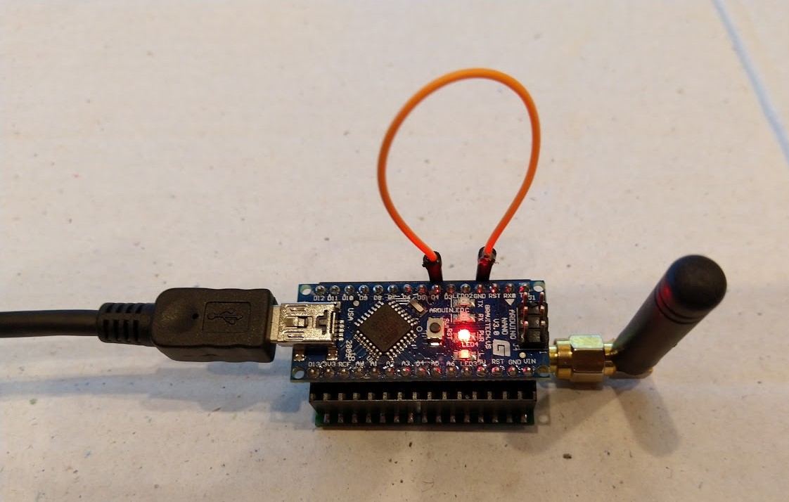
Arduino RFM69HCW Client in receive mode

I added code to dump the all the Arduino Nano Radio Shield RFM69/95 registers so I could compare it with my Adafruit RFM69HCW Radio Bonnet configuration. I also modified the code to set the three frequency registers so they matched the sample values based on the calculation in the RFM69HCW datasheet. I spent a lot of time manually configuring individual registers on the Adafruit bonnet (ignoring registers like 0x24 RegRssiValue).

void bareRFM69::dumpRegisters(Stream& out)
{
  for (int i = 0; i <= 0x3d; i++) {
    out.print("0x");
    out.print(i, HEX);
    out.print(": 0x");
    out.println(this->readRegister(i), HEX);
  }
}

void plainRFM69::setFrequency(uint32_t freq){
     uint64_t frf = ((uint64_t)freq << 19) / 32000000;
    this->setFrf(frf);
}

After much “trial and error” I found that my Arduino device would only receive messages from my Windows 10 IoT Core device when a third Arduino device was transmitting.

21:10:50.819 -> 0x0: 0x0
21:10:50.819 -> 0x1: 0x4
21:10:50.852 -> 0x2: 0x0
21:10:50.852 -> 0x3: 0x1A
21:10:50.852 -> 0x4: 0xB
21:10:50.886 -> 0x5: 0x0
21:10:50.886 -> 0x6: 0x52
21:10:50.886 -> 0x7: 0xE4
21:10:50.920 -> 0x8: 0xC0
21:10:50.920 -> 0x9: 0x0
21:10:50.920 -> 0xA: 0x41
21:10:50.954 -> 0xB: 0x40
21:10:50.954 -> 0xC: 0x2
21:10:50.954 -> 0xD: 0x92
21:10:50.988 -> 0xE: 0xF5
21:10:50.988 -> 0xF: 0x20
21:10:50.988 -> 0x10: 0x24
21:10:51.022 -> 0x11: 0x9F
21:10:51.022 -> 0x12: 0x9
21:10:51.056 -> 0x13: 0x1A
21:10:51.056 -> 0x14: 0x40
21:10:51.056 -> 0x15: 0xB0
21:10:51.089 -> 0x16: 0x7B
21:10:51.089 -> 0x17: 0x9B
21:10:51.089 -> 0x18: 0x88
21:10:51.124 -> 0x19: 0x55
21:10:51.124 -> 0x1A: 0x8B
21:10:51.124 -> 0x1B: 0x40
21:10:51.157 -> 0x1C: 0x80
21:10:51.157 -> 0x1D: 0x6
21:10:51.157 -> 0x1E: 0x10
21:10:51.191 -> 0x1F: 0x0
21:10:51.191 -> 0x20: 0x0
21:10:51.191 -> 0x21: 0x0
21:10:51.226 -> 0x22: 0x0
21:10:51.226 -> 0x23: 0x2
21:10:51.226 -> 0x24: 0xFF
21:10:51.260 -> 0x25: 0x0
21:10:51.260 -> 0x26: 0x5
21:10:51.293 -> 0x27: 0x80
21:10:51.293 -> 0x28: 0x0
21:10:51.293 -> 0x29: 0xFF
21:10:51.328 -> 0x2A: 0x0
21:10:51.328 -> 0x2B: 0x0
21:10:51.328 -> 0x2C: 0x0
21:10:51.363 -> 0x2D: 0x3
21:10:51.363 -> 0x2E: 0x98
21:10:51.363 -> 0x2F: 0x1
21:10:51.363 -> 0x30: 0x1
21:10:51.397 -> 0x31: 0x1
21:10:51.397 -> 0x32: 0x1
21:10:51.397 -> 0x33: 0x0
21:10:51.432 -> 0x34: 0x0
21:10:51.432 -> 0x35: 0x0
21:10:51.466 -> 0x36: 0x0
21:10:51.466 -> 0x37: 0x50
21:10:51.466 -> 0x38: 0x4
21:10:51.500 -> 0x39: 0x0
21:10:51.500 -> 0x3A: 0x0
21:10:51.500 -> 0x3B: 0x0
21:10:51.535 -> 0x3C: 0x1
21:10:51.535 -> 0x3D: 0x0
21:10:51.535 -> Going Receiver!
21:10:51.672 -> Packet (4): 27
21:10:51.672 -> Packetloss detected!
21:10:52.151 -> Packet (4): 28
21:10:52.665 -> Packet (4): 29
21:10:53.182 -> Packet (4): 30
21:10:53.664 -> Packet (4): 31
21:10:54.665 -> Packet (4): 33
21:10:54.699 -> Packetloss detected!
21:10:55.178 -> Packet (4): 34
21:10:56.177 -> Packet (4): 36
21:10:56.177 -> Packetloss detected!
21:10:56.660 -> Packet (4): 37
21:10:57.180 -> Packet (4): 38
21:10:57.666 -> Packet (4): 39
21:10:58.151 -> Packet (4): 40
21:10:58.669 -> Packet (4): 41
21:10:59.186 -> Packet (4): 42
21:10:59.668 -> Packet (4): 43
21:11:00.191 -> Packet (4): 44
21:11:00.666 -> Packet (4): 45
21:11:01.182 -> Packet (4): 46
21:11:01.664 -> Packet (4): 47
21:11:02.183 -> Packet (4): 48
21:11:02.664 -> Packet (4): 49
21:11:03.182 -> Packet (4): 50
21:11:03.664 -> Packet (4): 51

I think the interoperability problem was caused by timing differences caused by the plainRFM69 library using AutoMode (see datasheet section 4.4) to sequence the transmit process rather than manually changing the mode etc.

AutoMode option looks promising and warrants further investigation but interoperability will be an issue.

void plainRFM69::sendPacket(void* buffer, uint8_t len){
    /*
        Just like with Receive mode, the automode is used.

        First, Rx mode is disabled by going into standby.
        Then the automode is set to start transmitting when FIFO level is above
        the thresshold, it stops transmitting after PacketSent is asserted.

        This results in a minimal Tx time and packetSent can be detected when
        automode is left again.
        
    */
    this->setMode(RFM69_MODE_SEQUENCER_ON | RFM69_MODE_STANDBY);
    this->setAutoMode(RFM69_AUTOMODE_ENTER_RISING_FIFOLEVEL, RFM69_AUTOMODE_EXIT_RISING_PACKETSENT, RFM69_AUTOMODE_INTERMEDIATEMODE_TRANSMITTER);
    // perhaps RFM69_AUTOMODE_ENTER_RISING_FIFONOTEMPTY is faster?
    
    // set it into automode for transmitting

    // p22 - Turn on the high power boost registers in transmitting mode.
    if (this->tx_power_boosted)
    {
        this->setPa13dBm1(true);
        this->setPa13dBm2(true);
    }

    // write the fifo.
    this->state = RFM69_PLAIN_STATE_SENDING; // set the state to sending.
    this->writeFIFO(buffer, len);
}

Looks like I need to investigate some of the other Arduino library options.

RFM69 hat library Part4A

Transmit Basic Client Selection

My first milestone was to get my Adafruit RFM69HCW Radio Bonnet 433/868/915MHz sending packets to a program running on an Arduino device.

On GitHub there were quite a few RFM69 libraries, many of which were “based on”/”inspired by” the library by Felix Rusu from lowerPowerLab. (I have a number of LowPwerLab devices and they are pretty robust and reliable)

https://github.com/LowPowerLab/RFM69
https://github.com/dltech/RFM69
https://github.com/UKHASnet/ukhasnet-rfm69
https://github.com/jdesbonnet/RFM69_LPC812_firmware
https://github.com/grilletjesus
https://github.com/SamClarke2012/RFM69-AVR
https://github.com/boti7/RFM69-driver
https://github.com/ahessling/RFM69-STM32
https://github.com/tanchgen/wl_light
https://github.com/floxo/rfm69
https://github.com/JohnOH/raspirf
https://github.com/jgromes/RadioLib
https://github.com/flok99/RFM69
https://github.com/noearchimede/RFM69
https://gitlab.com/sedgwickcharles/RFM69
https://github.com/j54n1n/rfm69
https://github.com/DeltaNova/RFM69W
https://github.com/shaunhey/rfm69-elster
https://github.com/ivan-kralik/rfm69
https://github.com/rasmatic
https://github.com/iwanders/plainRFM69
https://www.hoperf.com/data/upload/back/20181204/RFM69-LCD-Listen-mode-code.rar

I was looking for something like the Arduino-LoRa library by Sandeep Mistry which was a fairly lightweight wrapper for the HopeRF RFM9X family of devices. I was looking for a library that didn’t change many of the default settings, have any in memory buffering or an implementation which included retries or transmit power adjustments.

The first version of the code to send packets was based on the example in part3.

public sealed class StartupTask : IBackgroundTask
{
    private const int ChipSelectLine = 1;
    private const int ResetLine = 25;
    private Rfm69HcwDevice rfm69Device = new Rfm69HcwDevice(ChipSelectLine, ResetLine);

    const double RH_RF6M9HCW_FXOSC = 32000000.0;
    const double RH_RFM69HCW_FSTEP = RH_RF6M9HCW_FXOSC / 524288.0;

    const byte NetworkID = 100;
    const byte NodeAddressFrom = 0x03;
    const byte NodeAddressTo = 0x02;


    public void Run(IBackgroundTaskInstance taskInstance)
    {
        rfm69Device.RegisterDump();

        // regOpMode standby
        rfm69Device.RegisterWriteByte(0x01, 0b00000100);

        // BitRate MSB/LSB
        rfm69Device.RegisterWriteByte(0x03, 0x34);
        rfm69Device.RegisterWriteByte(0x04, 0x00);

        // Frequency deviation
        rfm69Device.RegisterWriteByte(0x05, 0x02);
        rfm69Device.RegisterWriteByte(0x06, 0x3d);

        // Calculate the frequency according to the datasheett
        byte[] bytes = BitConverter.GetBytes((uint)(915000000.0 / RH_RFM69HCW_FSTEP));
        Debug.WriteLine("Byte Hex 0x{0:x2} 0x{1:x2} 0x{2:x2} 0x{3:x2}", bytes[0], bytes[1], bytes[2], bytes[3]);
        rfm69Device.RegisterWriteByte(0x07, bytes[2]);
        rfm69Device.RegisterWriteByte(0x08, bytes[1]);
        rfm69Device.RegisterWriteByte(0x09, bytes[0]);

        rfm69Device.RegisterWriteByte(0x38, 0x04);

        rfm69Device.RegisterDump();

        while (true)
        {
            // Standby mode while loading message into FIFO
            rfm69Device.RegisterWriteByte(0x01, 0b00000100);
            byte[] messageBuffer = BitConverter.GetBytes((uint)0);
            rfm69Device.RegisterWrite(0x0, messageBuffer);

            // Transmit mode once FIFO loaded
            rfm69Device.RegisterWriteByte(0x01, 0b00001100);

            // Wait until send done, no timeouts in PoC
            Debug.WriteLine("Send-wait");
            byte IrqFlags = rfm69Device.RegisterReadByte(0x28); // RegIrqFlags2
            while ((IrqFlags & 0b00001000) == 0)  // wait until TxDone cleared
            {
                Task.Delay(10).Wait();
                IrqFlags = rfm69Device.RegisterReadByte(0x28); // RegIrqFlags
                Debug.Write(".");
            }
            Debug.WriteLine("");

            // Standby mode while sleeping
            rfm69Device.RegisterWriteByte(0x01, 0b00000100);
            Debug.WriteLine($"{DateTime.Now.ToShortTimeString()}Send-Done");

            Task.Delay(5000).Wait();
        }
    }
}

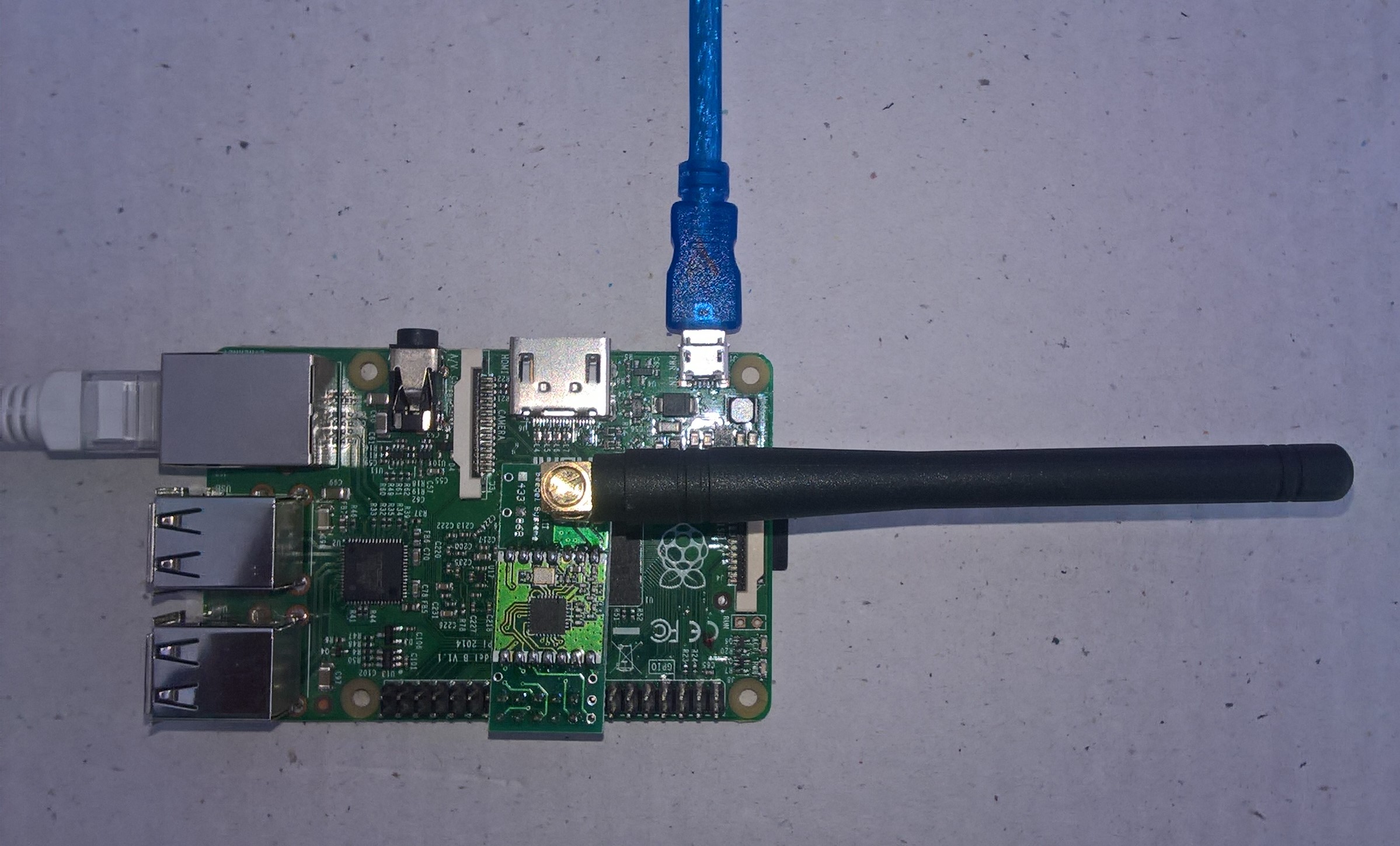
For testing my client device was an Easy Sensors Arduino Nano Radio Shield RFM69/95

EasySensors Arduino Nano Shield

I could see bytes getting put in the send buffer and the PacketSent bit flag in RegIrqFlags2 register was getting sent which was positive.

RFM69 hat library Part3

Initially I tried to used the RegisterManager code from my RFM9XIoTCore library but will have to make some modifications to cope with the different Reset pin timings for the RFM69HCW device and the Reset pin not being connected on the Seegle Systeme RaspyFRM.

When I first ran the test harness I found the 3 frequency registers (RegFrfMsb, RegFrfMid, RegFrfLsb) were not getting set as I expected.

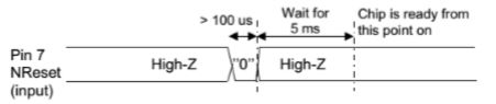
RFM69HCW reset timing diagram

After re-reading the RFM69HCW datasheet I noticed “should be pulled low for a hundred microseconds”, whereas the RFM95 datasheet had “should be pulled high for a hundred microseconds”.

RFM9X Reset timing diagram

After updating the reset GPIO pin code I could successfully set the frequency to 868MHz and then read it back

Register dump
Register 0x00 - Value 0X00 - Bits 00000000
Register 0x01 - Value 0X04 - Bits 00000100
Register 0x02 - Value 0X00 - Bits 00000000
Register 0x03 - Value 0X1a - Bits 00011010
Register 0x04 - Value 0X0b - Bits 00001011
Register 0x05 - Value 0X00 - Bits 00000000
Register 0x06 - Value 0X52 - Bits 01010010
Register 0x07 - Value 0Xe4 - Bits 11100100
Register 0x08 - Value 0Xc0 - Bits 11000000
Register 0x09 - Value 0X00 - Bits 00000000
Register 0x0a - Value 0X41 - Bits 01000001
Register 0x0b - Value 0X40 - Bits 01000000
Register 0x0c - Value 0X02 - Bits 00000010
Register 0x0d - Value 0X92 - Bits 10010010
Register 0x0e - Value 0Xf5 - Bits 11110101
Register 0x0f - Value 0X20 - Bits 00100000
Register 0x10 - Value 0X24 - Bits 00100100
Register 0x11 - Value 0X9f - Bits 10011111
Register 0x12 - Value 0X09 - Bits 00001001
Register 0x13 - Value 0X1a - Bits 00011010
Register 0x14 - Value 0X40 - Bits 01000000
Register 0x15 - Value 0Xb0 - Bits 10110000
Register 0x16 - Value 0X7b - Bits 01111011
Register 0x17 - Value 0X9b - Bits 10011011
Register 0x18 - Value 0X08 - Bits 00001000
Register 0x19 - Value 0X86 - Bits 10000110
Register 0x1a - Value 0X8a - Bits 10001010
Register 0x1b - Value 0X40 - Bits 01000000
Register 0x1c - Value 0X80 - Bits 10000000
Register 0x1d - Value 0X06 - Bits 00000110
Register 0x1e - Value 0X10 - Bits 00010000
Register 0x1f - Value 0X00 - Bits 00000000
Register 0x20 - Value 0X00 - Bits 00000000
Register 0x21 - Value 0X00 - Bits 00000000
Register 0x22 - Value 0X00 - Bits 00000000
Register 0x23 - Value 0X02 - Bits 00000010
Register 0x24 - Value 0Xff - Bits 11111111
Register 0x25 - Value 0X00 - Bits 00000000
Register 0x26 - Value 0X05 - Bits 00000101
Register 0x27 - Value 0X80 - Bits 10000000
Register 0x28 - Value 0X00 - Bits 00000000
Register 0x29 - Value 0Xff - Bits 11111111
Register 0x2a - Value 0X00 - Bits 00000000
Register 0x2b - Value 0X00 - Bits 00000000
Register 0x2c - Value 0X00 - Bits 00000000
Register 0x2d - Value 0X03 - Bits 00000011
Register 0x2e - Value 0X98 - Bits 10011000
Register 0x2f - Value 0X00 - Bits 00000000
Register 0x30 - Value 0X00 - Bits 00000000
Register 0x31 - Value 0X00 - Bits 00000000
Register 0x32 - Value 0X00 - Bits 00000000
Register 0x33 - Value 0X00 - Bits 00000000
Register 0x34 - Value 0X00 - Bits 00000000
Register 0x35 - Value 0X00 - Bits 00000000
Register 0x36 - Value 0X00 - Bits 00000000
Register 0x37 - Value 0X10 - Bits 00010000
Register 0x38 - Value 0X40 - Bits 01000000
Register 0x39 - Value 0X00 - Bits 00000000
Register 0x3a - Value 0X00 - Bits 00000000
Register 0x3b - Value 0X00 - Bits 00000000
Register 0x3c - Value 0X0f - Bits 00001111
Register 0x3d - Value 0X02 - Bits 00000010
Read RegOpMode (read byte)
Reg OpMode 0x04
Byte Hex 0x00 0x00 0xd9 0x00
Register dump
Register 0x00 - Value 0X00 - Bits 00000000
Register 0x01 - Value 0X04 - Bits 00000100
Register 0x02 - Value 0X00 - Bits 00000000
Register 0x03 - Value 0X1a - Bits 00011010
Register 0x04 - Value 0X0b - Bits 00001011
Register 0x05 - Value 0X00 - Bits 00000000
Register 0x06 - Value 0X52 - Bits 01010010
Register 0x07 - Value 0Xd9 - Bits 11011001
Register 0x08 - Value 0X00 - Bits 00000000
Register 0x09 - Value 0X00 - Bits 00000000
Register 0x0a - Value 0X41 - Bits 01000001
Register 0x0b - Value 0X40 - Bits 01000000
Register 0x0c - Value 0X02 - Bits 00000010
Register 0x0d - Value 0X92 - Bits 10010010
Register 0x0e - Value 0Xf5 - Bits 11110101
Register 0x0f - Value 0X20 - Bits 00100000
Register 0x10 - Value 0X24 - Bits 00100100
Register 0x11 - Value 0X9f - Bits 10011111
Register 0x12 - Value 0X09 - Bits 00001001
Register 0x13 - Value 0X1a - Bits 00011010
Register 0x14 - Value 0X40 - Bits 01000000
Register 0x15 - Value 0Xb0 - Bits 10110000
Register 0x16 - Value 0X7b - Bits 01111011
Register 0x17 - Value 0X9b - Bits 10011011
Register 0x18 - Value 0X08 - Bits 00001000
Register 0x19 - Value 0X86 - Bits 10000110
Register 0x1a - Value 0X8a - Bits 10001010
Register 0x1b - Value 0X40 - Bits 01000000
Register 0x1c - Value 0X80 - Bits 10000000
Register 0x1d - Value 0X06 - Bits 00000110
Register 0x1e - Value 0X10 - Bits 00010000
Register 0x1f - Value 0X00 - Bits 00000000
Register 0x20 - Value 0X00 - Bits 00000000
Register 0x21 - Value 0X00 - Bits 00000000
Register 0x22 - Value 0X00 - Bits 00000000
Register 0x23 - Value 0X02 - Bits 00000010
Register 0x24 - Value 0Xff - Bits 11111111
Register 0x25 - Value 0X00 - Bits 00000000
Register 0x26 - Value 0X05 - Bits 00000101
Register 0x27 - Value 0X80 - Bits 10000000
Register 0x28 - Value 0X00 - Bits 00000000
Register 0x29 - Value 0Xff - Bits 11111111
Register 0x2a - Value 0X00 - Bits 00000000
Register 0x2b - Value 0X00 - Bits 00000000
Register 0x2c - Value 0X00 - Bits 00000000
Register 0x2d - Value 0X03 - Bits 00000011
Register 0x2e - Value 0X98 - Bits 10011000
Register 0x2f - Value 0X00 - Bits 00000000
Register 0x30 - Value 0X00 - Bits 00000000
Register 0x31 - Value 0X00 - Bits 00000000
Register 0x32 - Value 0X00 - Bits 00000000
Register 0x33 - Value 0X00 - Bits 00000000
Register 0x34 - Value 0X00 - Bits 00000000
Register 0x35 - Value 0X00 - Bits 00000000
Register 0x36 - Value 0X00 - Bits 00000000
Register 0x37 - Value 0X10 - Bits 00010000
Register 0x38 - Value 0X40 - Bits 01000000
Register 0x39 - Value 0X00 - Bits 00000000
Register 0x3a - Value 0X00 - Bits 00000000
Register 0x3b - Value 0X00 - Bits 00000000
Register 0x3c - Value 0X0f - Bits 00001111
Register 0x3d - Value 0X02 - Bits 00000010

The next step is to extract the SPI register access functionality into a module and configure the bare minimum of settings required to get the RFM69 to transmit.

RFM69 shield library Part2

Register Dump

Next step was to dump all registers (0x00 RegFifo thru 0x4F RegTemp2) of the RFM69HCW device.

/*
    Copyright ® 2019 May devMobile Software, All Rights Reserved

	 MIT License


	 Permission is hereby granted, free of charge, to any person obtaining a copy
	 of this software and associated documentation files (the "Software"), to deal
    in the Software without restriction, including without limitation the rights
	 to use, copy, modify, merge, publish, distribute, sublicense, and/or sell
	 copies of the Software, and to permit persons to whom the Software is
    furnished to do so, subject to the following conditions:

    The above copyright notice and this permission notice shall be included in all
	 copies or substantial portions of the Software.

    THE SOFTWARE IS PROVIDED "AS IS", WITHOUT WARRANTY OF ANY KIND, EXPRESS OR
	 IMPLIED, INCLUDING BUT NOT LIMITED TO THE WARRANTIES OF MERCHANTABILITY,
    FITNESS FOR A PARTICULAR PURPOSE AND NONINFRINGEMENT. IN NO EVENT SHALL THE
	 AUTHORS OR COPYRIGHT HOLDERS BE LIABLE FOR ANY CLAIM, DAMAGES OR OTHER
	 LIABILITY, WHETHER IN AN ACTION OF CONTRACT, TORT OR OTHERWISE, ARISING FROM,
    OUT OF OR IN CONNECTION WITH THE SOFTWARE OR THE USE OR OTHER DEALINGS IN THE
	 SOFTWARE

	 RegFiFo 0x00 thru RegPacketConfig2 0x3D

*/
namespace devMobile.IoT.Rfm69Hcw.RegisterScan
{
	using System;
	using System.Diagnostics;
	using System.Threading.Tasks;
	using Windows.ApplicationModel.Background;
	using Windows.Devices.Spi;

	public sealed class Rfm69HcwDevice
	{
		private SpiDevice rfm69Hcw;

		public Rfm69HcwDevice(int chipSelectPin)
		{
			SpiController spiController = SpiController.GetDefaultAsync().AsTask().GetAwaiter().GetResult();
			var settings = new SpiConnectionSettings(chipSelectPin)
			{
				ClockFrequency = 500000,
				Mode = SpiMode.Mode0,
			};

			rfm69Hcw = spiController.GetDevice(settings);
		}

		public Byte RegisterReadByte(byte registerAddress)
		{
			byte[] writeBuffer = new byte[] { registerAddress };
			byte[] readBuffer = new byte[1];
			Debug.Assert(rfm69Hcw != null);

			rfm69Hcw.TransferSequential(writeBuffer, readBuffer);

			return readBuffer[0];
		}
	}

	public sealed class StartupTask : IBackgroundTask
	{
		private const int ChipSelectLine = 0;
		private Rfm69HcwDevice rfm69HcwDevice = new Rfm69HcwDevice(ChipSelectLine);

		public void Run(IBackgroundTaskInstance taskInstance)
		{

			while (true)
			{
				for (byte registerIndex = 0; registerIndex <= 0x4F; registerIndex++)
				{
					byte registerValue = rfm69HcwDevice.RegisterReadByte(registerIndex);

					Debug.WriteLine("Register 0x{0:x2} - Value 0X{1:x2} - Bits {2}", registerIndex, registerValue, Convert.ToString(registerValue, 2).PadLeft(8, '0'));
				}

				Task.Delay(10000).Wait();
			}
		}
	}
}

I checked a selection of values from the Debug output and they matched the defaults in the datasheet e.g. 0x07-RegFrfMsb 0xE4, 0x08-RegFrfMid 0xC0, 0x09-RegFrfLsb 0x00, 0x2C-RegPreamble 0x0, 0x2D-RegPreamble 0x03 and 0x4E-RegTemp1 0x01.

Register 0x00 - Value 0X00 - Bits 00000000
Register 0x01 - Value 0X04 - Bits 00000100
Register 0x02 - Value 0X00 - Bits 00000000
Register 0x03 - Value 0X1a - Bits 00011010
Register 0x04 - Value 0X0b - Bits 00001011
Register 0x05 - Value 0X00 - Bits 00000000
Register 0x06 - Value 0X52 - Bits 01010010
Register 0x07 - Value 0Xe4 - Bits 11100100
Register 0x08 - Value 0Xc0 - Bits 11000000
Register 0x09 - Value 0X00 - Bits 00000000
Register 0x0a - Value 0X41 - Bits 01000001
Register 0x0b - Value 0X40 - Bits 01000000
Register 0x0c - Value 0X02 - Bits 00000010
Register 0x0d - Value 0X92 - Bits 10010010
Register 0x0e - Value 0Xf5 - Bits 11110101
Register 0x0f - Value 0X20 - Bits 00100000
Register 0x10 - Value 0X24 - Bits 00100100
Register 0x11 - Value 0X9f - Bits 10011111
Register 0x12 - Value 0X09 - Bits 00001001
Register 0x13 - Value 0X1a - Bits 00011010
Register 0x14 - Value 0X40 - Bits 01000000
Register 0x15 - Value 0Xb0 - Bits 10110000
Register 0x16 - Value 0X7b - Bits 01111011
Register 0x17 - Value 0X9b - Bits 10011011
Register 0x18 - Value 0X08 - Bits 00001000
Register 0x19 - Value 0X86 - Bits 10000110
Register 0x1a - Value 0X8a - Bits 10001010
Register 0x1b - Value 0X40 - Bits 01000000
Register 0x1c - Value 0X80 - Bits 10000000
Register 0x1d - Value 0X06 - Bits 00000110
Register 0x1e - Value 0X10 - Bits 00010000
Register 0x1f - Value 0X00 - Bits 00000000
Register 0x20 - Value 0X00 - Bits 00000000
Register 0x21 - Value 0X00 - Bits 00000000
Register 0x22 - Value 0X00 - Bits 00000000
Register 0x23 - Value 0X02 - Bits 00000010
Register 0x24 - Value 0Xff - Bits 11111111
Register 0x25 - Value 0X00 - Bits 00000000
Register 0x26 - Value 0X05 - Bits 00000101
Register 0x27 - Value 0X80 - Bits 10000000
Register 0x28 - Value 0X00 - Bits 00000000
Register 0x29 - Value 0Xff - Bits 11111111
Register 0x2a - Value 0X00 - Bits 00000000
Register 0x2b - Value 0X00 - Bits 00000000
Register 0x2c - Value 0X00 - Bits 00000000
Register 0x2d - Value 0X03 - Bits 00000011
Register 0x2e - Value 0X98 - Bits 10011000
Register 0x2f - Value 0X00 - Bits 00000000
Register 0x30 - Value 0X00 - Bits 00000000
Register 0x31 - Value 0X00 - Bits 00000000
Register 0x32 - Value 0X00 - Bits 00000000
Register 0x33 - Value 0X00 - Bits 00000000
Register 0x34 - Value 0X00 - Bits 00000000
Register 0x35 - Value 0X00 - Bits 00000000
Register 0x36 - Value 0X00 - Bits 00000000
Register 0x37 - Value 0X10 - Bits 00010000
Register 0x38 - Value 0X40 - Bits 01000000
Register 0x39 - Value 0X00 - Bits 00000000
Register 0x3a - Value 0X00 - Bits 00000000
Register 0x3b - Value 0X00 - Bits 00000000
Register 0x3c - Value 0X0f - Bits 00001111
Register 0x3d - Value 0X02 - Bits 00000010
Register 0x3e - Value 0X00 - Bits 00000000
Register 0x3f - Value 0X00 - Bits 00000000
Register 0x40 - Value 0X00 - Bits 00000000
Register 0x41 - Value 0X00 - Bits 00000000
Register 0x42 - Value 0X00 - Bits 00000000
Register 0x43 - Value 0X00 - Bits 00000000
Register 0x44 - Value 0X00 - Bits 00000000
Register 0x45 - Value 0X00 - Bits 00000000
Register 0x46 - Value 0X00 - Bits 00000000
Register 0x47 - Value 0X00 - Bits 00000000
Register 0x48 - Value 0X00 - Bits 00000000
Register 0x49 - Value 0X00 - Bits 00000000
Register 0x4a - Value 0X00 - Bits 00000000
Register 0x4b - Value 0X00 - Bits 00000000
Register 0x4c - Value 0X00 - Bits 00000000
Register 0x4d - Value 0X00 - Bits 00000000
Register 0x4e - Value 0X01 - Bits 00000001
Register 0x4f - Value 0X00 - Bits 00000000

RFM69 shield library Part1

Register Read

After building an RFM95 Windows 10 IoT Core C# library I wanted to see if I could source a couple of RFM69HCW hats and write another library. For some applications the RFM69HCW with the variety and number of low-power client devices available plus, its built in payload encryption and addressing make it a better option. For the RFM9X library I purchased several RM9X Raspberry PI Hats but I can only find a couple (May 2019) of suitable RFM69HCW ones.

  • Adafruit RFM69HCW Radio Bonnet 433/868/915MHz USD19.95
  • Seegel Systeme RaspyRFMII EUR17.90

I wanted a lightweight RFM69HCW library which didn’t try to hide how the chip functioned, and in the future could be configured to work with other vendors’ shields.

AdaFruit LoRa 9X/RFM69HCW Radio Bonnet
Seegel Systeme RaspyRFM-II

The first step was to build a basic universal windows platform (UWP) background task to confirm that I could reliably communicate with the AdaFruit shield over the SPI bus by reading a single register value (RegVersion the silicon version specified in the vendor datasheet).

/*
    Copyright ® 2019 May devMobile Software, All Rights Reserved
 
    MIT License

    Permission is hereby granted, free of charge, to any person obtaining a copy
    of this software and associated documentation files (the "Software"), to deal
    in the Software without restriction, including without limitation the rights
    to use, copy, modify, merge, publish, distribute, sublicense, and/or sell
    copies of the Software, and to permit persons to whom the Software is
    furnished to do so, subject to the following conditions:

    The above copyright notice and this permission notice shall be included in all
    copies or substantial portions of the Software.

    THE SOFTWARE IS PROVIDED "AS IS", WITHOUT WARRANTY OF ANY KIND, EXPRESS OR
    IMPLIED, INCLUDING BUT NOT LIMITED TO THE WARRANTIES OF MERCHANTABILITY,
    FITNESS FOR A PARTICULAR PURPOSE AND NONINFRINGEMENT. IN NO EVENT SHALL THE
    AUTHORS OR COPYRIGHT HOLDERS BE LIABLE FOR ANY CLAIM, DAMAGES OR OTHER
    LIABILITY, WHETHER IN AN ACTION OF CONTRACT, TORT OR OTHERWISE, ARISING FROM,
    OUT OF OR IN CONNECTION WITH THE SOFTWARE OR THE USE OR OTHER DEALINGS IN THE
    SOFTWARE

	 CS : CE1
	 RST : GPIO25
	 IRQ : GPIO22 (DIO0)
	 Unused : GPIO23 (DIO1)
	 Unused : GPIO24 (DIO2)
 */
namespace devMobile.IoT.Rfm69hcw.AdafruitSPI
{
	using System;
	using System.Diagnostics;
	using System.Threading;
	using Windows.ApplicationModel.Background;
	using Windows.Devices.Spi;

	public sealed class StartupTask : IBackgroundTask
	{
		private const byte RegVersion = 0x10;

		public void Run(IBackgroundTaskInstance taskInstance)
		{
			SpiController spiController = SpiController.GetDefaultAsync().AsTask().GetAwaiter().GetResult();
			var settings = new SpiConnectionSettings(1)
			{
				ClockFrequency = 500000,
				Mode = SpiMode.Mode0,
			};

			SpiDevice Device = spiController.GetDevice(settings);

			while (true)
			{
				byte[] writeBuffer = new byte[] { RegVersion }; // RegVersion
				byte[] readBuffer = new byte[1];

				Device.TransferSequential(writeBuffer, readBuffer);

				byte registerValue = readBuffer[0];
				Debug.WriteLine("Register 0x{0:x2} - Value 0X{1:x2} - Bits {2}", RegVersion, registerValue, Convert.ToString(registerValue, 2).PadLeft(8, '0'));

				Thread.Sleep(10000);
			}
		}
	}
}

The AdaFruit hat uses chip select 1

/*
    Copyright ® 2019 May devMobile Software, All Rights Reserved
 
    MIT License

    Permission is hereby granted, free of charge, to any person obtaining a copy
    of this software and associated documentation files (the "Software"), to deal
    in the Software without restriction, including without limitation the rights
    to use, copy, modify, merge, publish, distribute, sublicense, and/or sell
    copies of the Software, and to permit persons to whom the Software is
    furnished to do so, subject to the following conditions:

    The above copyright notice and this permission notice shall be included in all
    copies or substantial portions of the Software.

    THE SOFTWARE IS PROVIDED "AS IS", WITHOUT WARRANTY OF ANY KIND, EXPRESS OR
    IMPLIED, INCLUDING BUT NOT LIMITED TO THE WARRANTIES OF MERCHANTABILITY,
    FITNESS FOR A PARTICULAR PURPOSE AND NONINFRINGEMENT. IN NO EVENT SHALL THE
    AUTHORS OR COPYRIGHT HOLDERS BE LIABLE FOR ANY CLAIM, DAMAGES OR OTHER
    LIABILITY, WHETHER IN AN ACTION OF CONTRACT, TORT OR OTHERWISE, ARISING FROM,
    OUT OF OR IN CONNECTION WITH THE SOFTWARE OR THE USE OR OTHER DEALINGS IN THE
    SOFTWARE

    The RaspyRFM is plugged into the Raspberry PI of pin 17-26.

    From the docs for the dual RFM69 mini 
    17 -> 3,3 V
    18 (GPIO 24) -> DIO1 bei Einzelmodul, DIO0 Slave bei Doppelmodul
    19 (MOSI) -> MOSI
    20 -> GND
    21 (MISO) ->MISO
    22 (GPIO 25) -> DIO0
    23 (SCK) -> SCK
    24 (CE0) -> NSS Master
    25 -> GND
    26 (CE1) -> DIO2 bei Einzelmodul, NSS Slave bei Doppelmodul
 */
namespace devMobile.IoT.Rfm69hcw.SeegelSpi
{
	using System;
	using System.Diagnostics;
	using System.Threading;
	using Windows.ApplicationModel.Background;
	using Windows.Devices.Spi;

	public sealed class StartupTask : IBackgroundTask
	{
		private const byte RegVersion = 0x10;

		public void Run(IBackgroundTaskInstance taskInstance)
		{
			SpiController spiController = SpiController.GetDefaultAsync().AsTask().GetAwaiter().GetResult();
			var settings = new SpiConnectionSettings(0)
			{
				ClockFrequency = 500000,
				Mode = SpiMode.Mode0,
			};

			SpiDevice Device = spiController.GetDevice(settings);

			while (true)
			{
				byte[] writeBuffer = new byte[] { RegVersion }; // RegVersion
				byte[] readBuffer = new byte[1];

				Device.TransferSequential(writeBuffer, readBuffer);

				byte registerValue = readBuffer[0];
				Debug.WriteLine("Register 0x{0:x2} - Value 0X{1:x2} - Bits {2}", RegVersion, registerValue, Convert.ToString(registerValue, 2).PadLeft(8, '0'));

				Thread.Sleep(10000);
			}
		}
	}
}


The Seegel hat uses chip select 0

Based on the datasheet the RegVersion (0x10) register the value (ox24) returned by both hats was correct.

'backgroundTaskHost.exe' (CoreCLR: CoreCLR_UWP_Domain): Loaded 'C:\Data\Programs\WindowsApps\Microsoft.NET.CoreFramework.Debug.2.2_2.2.27505.2_arm__8wekyb3d8bbwe\System.Threading.Thread.dll'. Skipped loading symbols. Module is optimized and the debugger option 'Just My Code' is enabled.
Register 0x10 - Value 0X24 - Bits 00100100

Next step is to dump all the registers of the HopeRF module

Grove Base Hat for Raspberry PI Zero Windows 10 IoT Core

During the week a package arrived from Seeedstudio with a Grove Base Hat for RPI Zero. So I have modified my Grove Base Hat for RPI Windows 10 IoT Core library to add support for the new shield.

Grove Base Hat for Raspberry PI Zero on Raspberry PI 3

The Raspberry PI Zero hat has a two less analog ports and a different device id so some conditional compile options were necessary

namespace devMobile.Windows10IoTCore.GroveBaseHatRPI
{
#if (!GROVE_BASE_HAT_RPI && !GROVE_BASE_HAT_RPI_ZERO)
#error Library must have at least one of GROVE_BASE_HAT_RPI or GROVE_BASE_HAT_RPI_ZERO defined
#endif

#if (GROVE_BASE_HAT_RPI && GROVE_BASE_HAT_RPI_ZERO)
#error Library must have at most one of GROVE_BASE_HAT_RPI or GROVE_BASE_HAT_RPI_ZERO defined
#endif

	public class AnalogPorts : IDisposable
	{
		private const int I2CAddress = 0x04;
		private const byte RegisterDeviceId = 0x0;
		private const byte RegisterVersion = 0x02;
		private const byte RegisterPowerSupplyVoltage = 0x29;
		private const byte RegisterRawBase = 0x10;
		private const byte RegisterVoltageBase = 0x20;
		private const byte RegisterValueBase = 0x30;
#if GROVE_BASE_HAT_RPI
		private const byte DeviceId = 0x0004;
#endif
#if GROVE_BASE_HAT_RPI_ZERO
		private const byte DeviceId = 0x0005;
#endif
		private I2cDevice Device= null;
		private bool Disposed = false;

		public enum AnalogPort
		{
			A0 = 0,
			A1 = 1,
			A2 = 2,
			A3 = 3,
			A4 = 4,
			A5 = 5,
#if GROVE_BASE_HAT_RPI
			A6 = 6,
			A7 = 7,
#endif
		};

The code updates have been “smoke” tested and I have updated the GitHub repository.

Grove Base Hat for Raspberry PI Windows 10 IoT Core

After some experimentation I have a proof of concept Windows 10 IoT Core library for accessing the Analog to Digital Convertor (ADC) on a Grove Base Hat for Raspberry PI.

I can read the raw, voltage & % values just fine but the Version number isn’t quite what I expected. In the python sample code I can see the register numbers etc.

def __init__(self, address=0x04):
self.address = address
self.bus = grove.i2c.Bus()

def read_raw(self, channel):
addr = 0x10 + channel
return self.read_register(addr)

# read input voltage (mV)
def read_voltage(self, channel):
addr = 0x20 + channel
return self.read_register(addr)

# input voltage / output voltage (%)
def read(self, channel):
addr = 0x30 + channel
return self.read_register(addr)

@property
def name(self):
id = self.read_register(0x0)
if id == RPI_HAT_PID:
return RPI_HAT_NAME
elif id == RPI_ZERO_HAT_PID:
return RPI_ZERO_HAT_NAME

@property
def version(self):
return self.read_register(0x3)

When I read register 0x3 to get the version info the value changes randomly. Format = register num, byte value, word value

0,4,4 1,134,10374 2,2,2 3,82,79 4,0,0 5,0,0 6,0,0 7,0,0 8,0,0 9,0,0 10,0,0 11,0,0 12,0,0 13,0,0 14,0,0 15,0,0 
0,4,4 1,134,10374 2,2,2 3,86,69 4,0,0 5,0,0 6,0,0 7,0,0 8,0,0 9,0,0 10,0,0 11,0,0 12,0,0 13,0,0 14,0,0 15,0,0 
0,4,4 1,134,10374 2,2,2 3,32,66 4,0,0 5,0,0 6,0,0 7,0,0 8,0,0 9,0,0 10,0,0 11,0,0 12,0,0 13,0,0 14,0,0 15,0,0 

It looks like register 1 or 2 (134/10374 or 2/2) might contain the device version information.

The code is available on GitHub here. Next time I purchase some gear from Seeedstudio I’ll include a Grove Base Hat For Raspberry PI Zero and extend the software so they work as well.

public sealed class StartupTask : IBackgroundTask
{
   private ThreadPoolTimer timer;
   private BackgroundTaskDeferral deferral;
   AnalogPorts analogPorts = new AnalogPorts();

   public void Run(IBackgroundTaskInstance taskInstance)
   {
      deferral = taskInstance.GetDeferral();

      analogPorts.Initialise();

      byte version = analogPorts.Version();
      Debug.WriteLine($"Version {version}");

      double powerSupplyVoltage = analogPorts.PowerSupplyVoltage();
      Debug.WriteLine($"Power supply voltage {powerSupplyVoltage}v");

      timer = ThreadPoolTimer.CreatePeriodicTimer(AnalogPorts, TimeSpan.FromSeconds(5));
   }

   void AnalogPorts(ThreadPoolTimer timer)
   {
      try
      {
         ushort valueRaw;
         valueRaw = analogPorts.ReadRaw(AnalogPorts.AnalogPort.A0);
         Debug.WriteLine($"A0 Raw {valueRaw}");

         double valueVoltage;
         valueVoltage = analogPorts.ReadVoltage(AnalogPorts.AnalogPort.A0);
         Debug.WriteLine($"A0 {valueVoltage}v");

         double value;
         value = analogPorts.Read(AnalogPorts.AnalogPort.A0);
         Debug.WriteLine($"A0 {value}");
      }
      catch (Exception ex)
      {
         Debug.WriteLine($"AnalogPorts Read failed {ex.Message}");
      }
   }
}

Grove Base Hat for Raspberry PI Investigation

For a couple of projects I had been using the Dexter industries GrovePI+ and the Grove Base Hat for Raspberry PI looked like a cheaper alternative for many applications, but it lacked Windows 10 IoT Core support.

My first project was to build a Inter Integrated Circuit(I2C) device scanner to check that the Grove Base Hat STM32 MCU I2C client implementation on a “played nice” with Windows 10 IoT core.

My Visual Studio 2017 project (I2C Device Scanner) scans all the valid 7bit I2C addresses and in the debug output displayed the two “found” devices, a Grove- 3 Axis Accelerometer(+-16G) (ADXL345) and the Grove Base Hat for Raspberry PI.

backgroundTaskHost.exe' (CoreCLR: CoreCLR_UWP_Domain): Loaded 'C:\Data\Users\DefaultAccount\AppData\Local\DevelopmentFiles\I2CDeviceScanner-uwpVS.Debug_ARM.Bryn.Lewis\System.Diagnostics.Debug.dll'. Skipped loading symbols. Module is optimized and the debugger option 'Just My Code' is enabled.

'backgroundTaskHost.exe' (CoreCLR: CoreCLR_UWP_Domain): Loaded 'C:\Data\Users\DefaultAccount\AppData\Local\DevelopmentFiles\I2CDeviceScanner-uwpVS.Debug_ARM.Bryn.Lewis\System.Linq.dll'. Skipped loading symbols. Module is optimized and the debugger option 'Just My Code' is enabled.
Exception thrown: 'System.IO.FileNotFoundException' in devMobile.Windows10IoTCore.I2CDeviceScanner.winmd
WinRT information: Slave address was not acknowledged.
.......
Exception thrown: 'System.IO.FileNotFoundException' in devMobile.Windows10IoTCore.I2CDeviceScanner.winmd
WinRT information: Slave address was not acknowledged.

I2C Controller \\?\ACPI#MSFT8000#1#{a11ee3c6-8421-4202-a3e7-b91ff90188e4}\I2C1 has 2 devices
Address 0x4
Address 0x53
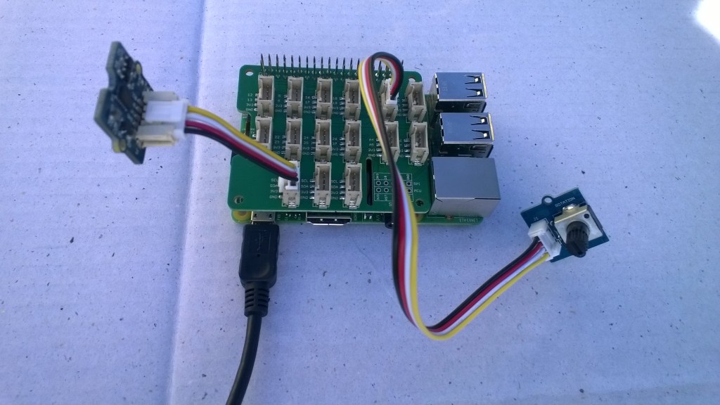
Raspberry PI with Grove Base Hat & ADXL345 & Rotary angle sensor
Raspberry PI with Grove Base Hat I2C test rig

The next step was to confirm I could read the device ID of the ADXL345 and the Grove Base Hat for RaspberryPI. I had to figure out the Grove Base Hat for RaspberryPI from the Seeedstudio Python code.

I2CDevicePinger ADXL345 Debug output

...
'backgroundTaskHost.exe' (CoreCLR: CoreCLR_UWP_Domain): Loaded 'C:\Data\Users\DefaultAccount\AppData\Local\DevelopmentFiles\I2CDevicePinger-uwpVS.Debug_ARM.Bryn.Lewis\System.Diagnostics.Debug.dll'. Skipped loading symbols. Module is optimized and the debugger option 'Just My Code' is enabled.
DeviceID 0XE5

The DeviceID for the ADXL345 matched the DEVID in the device datasheet.

I2CDevicePinger Debug output

'backgroundTaskHost.exe' (CoreCLR: CoreCLR_UWP_Domain): Loaded 'C:\Data\Users\DefaultAccount\AppData\Local\DevelopmentFiles\I2CDevicePinger-uwpVS.Debug_ARM.Bryn.Lewis\System.Diagnostics.Debug.dll'. Skipped loading symbols. Module is optimized and the debugger option 'Just My Code' is enabled.
DeviceID 0X4

The DeviceID for the Grove Base Hat for RaspberryPI matched

RPI_HAT_PID = 0x0004 in the Python code.

The last test application reads the raw value of the specified analog input

public async void Run(IBackgroundTaskInstance taskInstance)
{
   string aqs = I2cDevice.GetDeviceSelector();
   DeviceInformationCollection I2CBusControllers = await DeviceInformation.FindAllAsync(aqs);

   if (I2CBusControllers.Count != 1)
   {
      Debug.WriteLine("Unexpect number of I2C bus controllers found");
      return;
   }

   I2cConnectionSettings settings = new I2cConnectionSettings(0x04)
   {
      BusSpeed = I2cBusSpeed.StandardMode,
      SharingMode = I2cSharingMode.Shared,
   };

   using (I2cDevice device = I2cDevice.FromIdAsync(I2CBusControllers[0].Id, settings).AsTask().GetAwaiter().GetResult())
   {
      try
      {
         ushort value = 0;
         // From the Seeedstudio python
	 // 0x10 ~ 0x17: ADC raw data
	 // 0x20 ~ 0x27: input voltage
         // 0x29: output voltage (Grove power supply voltage)
         // 0x30 ~ 0x37: input voltage / output voltage						
         do
	 {
            byte[] writeBuffer = new byte[1] { 0x10 };
            byte[] readBuffer = new byte[2] { 0, 0 };

            device.WriteRead(writeBuffer, readBuffer);
            value = BitConverter.ToUInt16(readBuffer, 0);

            Debug.WriteLine($"Value {value}");

            Task.Delay(1000).GetAwaiter().GetResult();
         }
         while (value != 0);
      }
      Catch (Exception ex)
      {
         Debug.WriteLine(ex.Message);
      }
   }
}

GroveBaseHatRPIRegisterReader Debug output

'backgroundTaskHost.exe' (CoreCLR: CoreCLR_UWP_Domain): Loaded 'C:\Data\Users\DefaultAccount\AppData\Local\DevelopmentFiles\GroveBaseHatRPIRegisterReader-uwpVS.Debug_ARM.Bryn.Lewis\System.Diagnostics.Debug.dll'. Skipped loading symbols. Module is optimized and the debugger option 'Just My Code' is enabled.
Value 3685
Value 3685
Value 3688
Value 3681
Value 3681
Value 3688
Value 3688
Value 3683

The output changed when I adjusted the rotary angle sensor (0-4095) which confirmed I could reliably read the Analog input values.

The code for my test harness applications is available on github, the next step is to build a library for the Grove Base Hat for RaspberryPI

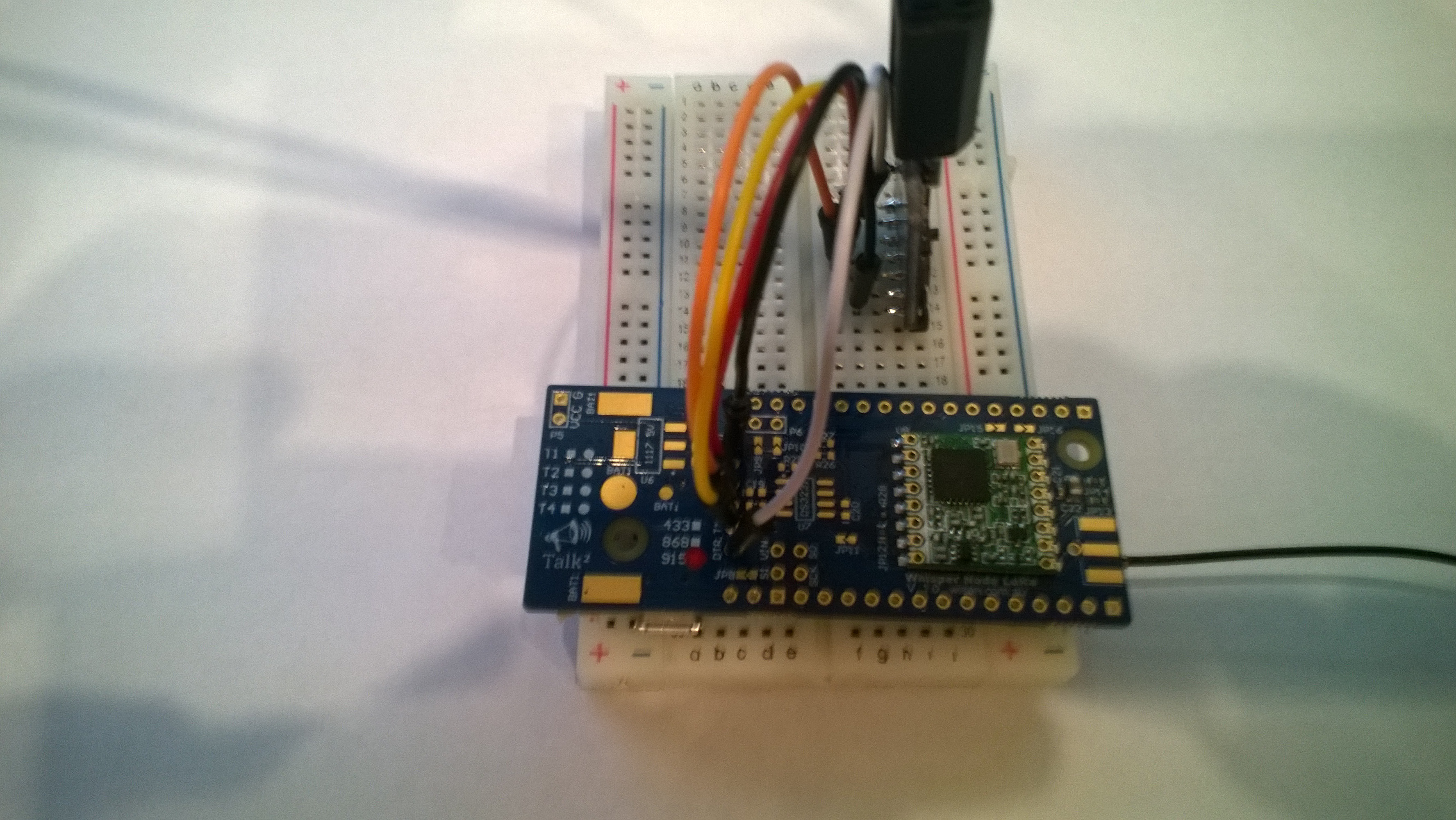
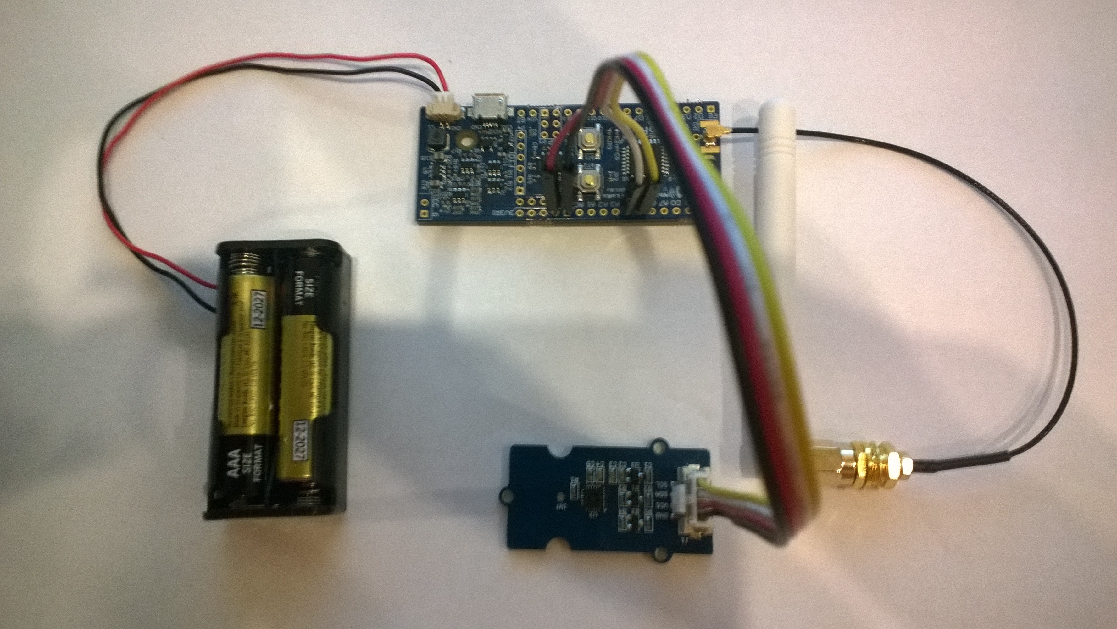
Wisen Whisper Node – LoRa 915 MHz Payload Addressing Client

This is a demo Wizen Whisper Node – LoRa client (based on one of the examples from Arduino-LoRa) that uploads telemetry data to my Windows 10 IoT Core on Raspberry PI field gateway proof of concept(PoC).

The Wisen Bitbucket repository had sample code based on the RadioHead library which was useful for port numbers. This device family supports 433MHz, 868MHz & 915Mz modules. Wisen has other RFM69 based devices as well.

Bill of materials (Prices Sep 2018)

  • Wizen Whisper Node LoRa (433, 868 or 900 MHz) AUD27.90
  • Seeedstudio Temperature and Humidity Sensor Pro USD11.50
  • Seeedstudio 4 pin Male Jumper to Grove 4 pin Conversion Cable USD2.90

The code is pretty basic, it reads a value from the Seeedstudio temperature and humidity sensor, then packs the payload and sets the necessary RFM9X/SX127X LoRa module configuration. It has no power conservation, advanced wireless configuration etc.

I needed to use jumpers to connect my device up

WisenPatch20180924

WisenLoRa20180924

/*
  Adapted from LoRa Duplex communication with Sync Word

  Sends temperature & humidity data from Seeedstudio 

  https://www.seeedstudio.com/Grove-Temperature-Humidity-Sensor-High-Accuracy-Min-p-1921.html

  To my Windows 10 IoT Core RFM 9X library

  
RFM9X.IoTCore Payload Addressing
*/ #include // include libraries #include #include const int csPin = 10; // LoRa radio chip select const int resetPin = 7; // LoRa radio reset const int irqPin = 2; // change for your board; must be a hardware interrupt pin // Field gateway configuration const char FieldGatewayAddress[] = "LoRaIoT1"; const float FieldGatewayFrequency = 915000000.0; const byte FieldGatewaySyncWord = 0x12 ; // Payload configuration const int PayloadSizeMaximum = 64 ; byte payload[PayloadSizeMaximum] = ""; const byte SensorReadingSeperator = ',' ; // Manual serial number configuration const char DeviceId[] = {"Wisen01"}; const int LoopSleepDelaySeconds = 10 ; void setup() { Serial.begin(9600); //while (!Serial); Serial.println("LoRa Setup"); // override the default CS, reset, and IRQ pins (optional) LoRa.setPins(csPin, resetPin, irqPin);// set CS, reset, IRQ pin if (!LoRa.begin(FieldGatewayFrequency)) { Serial.println("LoRa init failed. Check your connections."); while (true); } // Need to do this so field gateways pays attention to messsages from this device LoRa.enableCrc(); LoRa.setSyncWord(FieldGatewaySyncWord); //LoRa.dumpRegisters(Serial); Serial.println("LoRa Setup done."); // Configure the Seeedstudio TH02 temperature & humidity sensor Serial.println("TH02 setup"); TH02.begin(); delay(100); Serial.println("TH02 Setup done"); Serial.println("Setup done"); } void loop() { int payloadLength = 0 ; float temperature ; float humidity ; Serial.println("Loop called"); memset(payload, 0, sizeof(payload)); // prepare the payload header with "To" Address length (top nibble) and "From" address length (bottom nibble) payload[0] = (strlen(FieldGatewayAddress) << 4) | strlen( DeviceId ) ; payloadLength += 1; // Copy the "To" address into payload memcpy(&payload[payloadLength], FieldGatewayAddress, strlen(FieldGatewayAddress)); payloadLength += strlen(FieldGatewayAddress) ; // Copy the "From" into payload memcpy(&payload[payloadLength], DeviceId, strlen(DeviceId)); payloadLength += strlen(DeviceId) ; // Read the temperature and humidity values then display nicely temperature = TH02.ReadTemperature(); humidity = TH02.ReadHumidity(); Serial.print("T:"); Serial.print( temperature, 1 ) ; Serial.print( "C" ) ; Serial.print(" H:"); Serial.print( humidity, 0 ) ; Serial.println( "%" ) ; // Copy the temperature into the payload payload[ payloadLength] = 't'; payloadLength += 1 ; payload[ payloadLength] = ' '; payloadLength += 1 ; payloadLength += strlen( dtostrf(temperature, -1, 1, (char*)&payload[payloadLength])); payload[ payloadLength] = SensorReadingSeperator; payloadLength += sizeof(SensorReadingSeperator) ; // Copy the humidity into the payload payload[ payloadLength] = 'h'; payloadLength += 1 ; payload[ payloadLength] = ' '; payloadLength += 1 ; payloadLength += strlen( dtostrf(humidity, -1, 0, (char *)&payload[payloadLength])); // display info about payload then send it (No ACK) with LoRa unlike nRF24L01 Serial.print( "RFM9X/SX127X Payload length:"); Serial.print( payloadLength ); Serial.println( " bytes" ); LoRa.beginPacket(); LoRa.write( payload, payloadLength ); LoRa.endPacket(); Serial.println("Loop done"); delay(LoopSleepDelaySeconds * 1000l); }

In the debug output window the messages from the device looked like this

20:38:30-RX From Wisen01 PacketSnr 10.0 Packet RSSI -48dBm RSSI -104dBm = 11 byte message "t 22.2,h 91"
Sensor Wisen01t Value 22.2
Sensor Wisen01h Value 91
AzureIoTHubClient SendEventAsync start
AzureIoTHubClient SendEventAsync finish
The thread 0x14c0 has exited with code 0 (0x0).
The thread 0x788 has exited with code 0 (0x0).
20:38:40-RX From Wisen01 PacketSnr 9.8 Packet RSSI -48dBm RSSI -103dBm = 11 byte message "t 22.5,h 91"
Sensor Wisen01t Value 22.5
Sensor Wisen01h Value 91
AzureIoTHubClient SendEventAsync start
AzureIoTHubClient SendEventAsync finish
The thread 0x1124 has exited with code 0 (0x0).
The thread 0x129c has exited with code 0 (0x0).
20:38:50-RX From Wisen01 PacketSnr 9.3 Packet RSSI -47dBm RSSI -96dBm = 11 byte message "t 22.7,h 91"
Sensor Wisen01t Value 22.7
Sensor Wisen01h Value 91
AzureIoTHubClient SendEventAsync start
AzureIoTHubClient SendEventAsync finish
The thread 0x664 has exited with code 0 (0x0).

Then at my Azure IoT hub the data stream looked like this

WisenTalkLoRaAzureIoTHub

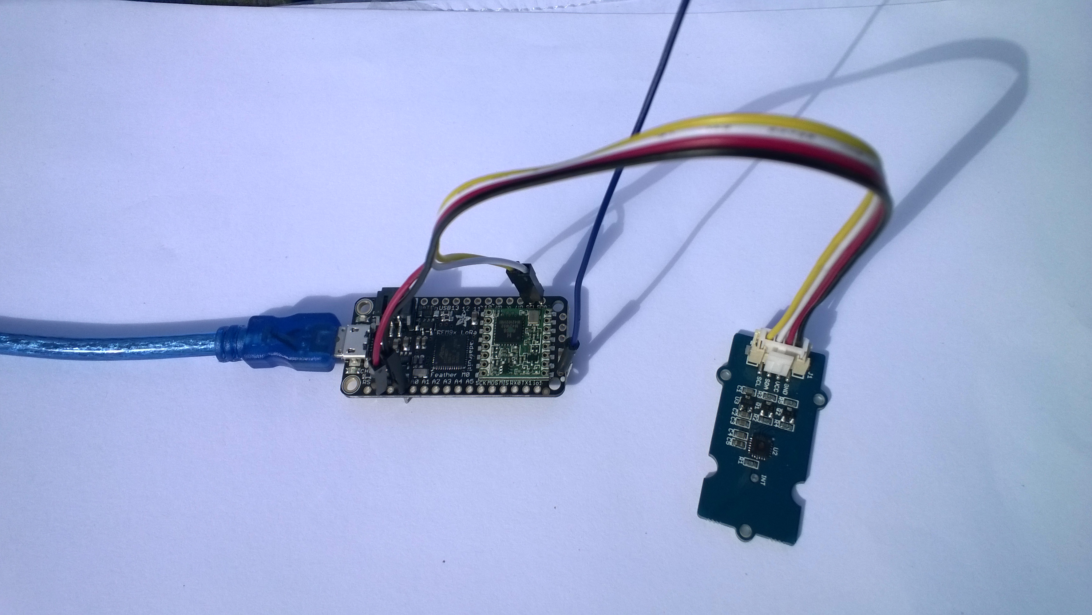
Adafruit Feather M0 RFM95 LoRa Radio Payload Addressing Client

This is a demo AdaFruit Feather Mo0 Radio with LoRa Radio Module client (based on one of the examples from Arduino-LoRa) that uploads telemetry data to my Windows 10 IoT Core on Raspberry PI field gateway proof of concept(PoC).

The Adafruit learn site had sample code based on the RadioHead library which was useful. This device supports 868MHz & 915Mz, there is are other Arduino 32u4 and 433MHz devices available.

Bill of materials (Prices Sep 2018)

  • Adafruit Feather M0 RFM95 LoRa Radio (433 or 900 MHz) USD34.95
  • Seeedstudio Temperature and Humidity Sensor Pro USD11.50
  • Seeedstudio 4 pin Male Jumper to Grove 4 pin Conversion Cable USD2.90

The code is pretty basic, it reads a value from the Seeedstudio temperature and humidity sensor, then packs the payload and sets the necessary RFM9X/SX127X LoRa module configuration, has no power conservation, advanced wireless configuration etc. I had to add an extra include from the dstrtof function

AdaFruitM0Feather

/*
  Adapted from LoRa Duplex communication with Sync Word

  Sends temperature & humidity data from Seeedstudio 

  https://www.seeedstudio.com/Grove-Temperature-Humidity-Sensor-High-Accuracy-Min-p-1921.html

  To my Windows 10 IoT Core RFM 9X library

  
RFM9X.IoTCore Payload Addressing
*/ #include #include #include #include const int csPin = 8; // LoRa radio chip select const int resetPin = 4; // LoRa radio reset const int irqPin = 3; // change for your board; must be a hardware interrupt pin // Field gateway configuration const char FieldGatewayAddress[] = "LoRaIoT1"; const float FieldGatewayFrequency = 915000000.0; const byte FieldGatewaySyncWord = 0x12 ; // Payload configuration const int PayloadSizeMaximum = 64 ; byte payload[PayloadSizeMaximum] = ""; const byte SensorReadingSeperator = ',' ; // Manual serial number configuration const char DeviceId[] = {"AdafruitM0"}; const int LoopSleepDelaySeconds = 10 ; void setup() { Serial.begin(9600); //while (!Serial); Serial.println("LoRa Setup"); // override the default CS, reset, and IRQ pins (optional) LoRa.setPins(csPin, resetPin, irqPin);// set CS, reset, IRQ pin if (!LoRa.begin(FieldGatewayFrequency)) { Serial.println("LoRa init failed. Check your connections."); while (true); } // Need to do this so field gateways pays attention to messages from this device LoRa.enableCrc(); LoRa.setSyncWord(FieldGatewaySyncWord); //LoRa.dumpRegisters(Serial); Serial.println("LoRa Setup done."); // Configure the Seeedstudio TH02 temperature & humidity sensor Serial.println("TH02 setup"); TH02.begin(); delay(100); Serial.println("TH02 Setup done"); Serial.println("Setup done"); } void loop() { int payloadLength = 0 ; float temperature ; float humidity ; Serial.println("Loop called"); memset(payload, 0, sizeof(payload)); // prepare the payload header with "To" Address length (top nibble) and "From" address length (bottom nibble) payload[0] = (strlen(FieldGatewayAddress) << 4) | strlen( DeviceId ) ; payloadLength += 1; // Copy the "To" address into payload memcpy(&payload[payloadLength], FieldGatewayAddress, strlen(FieldGatewayAddress)); payloadLength += strlen(FieldGatewayAddress) ; // Copy the "From" into payload memcpy(&payload[payloadLength], DeviceId, strlen(DeviceId)); payloadLength += strlen(DeviceId) ; // Read the temperature and humidity values then display nicely temperature = TH02.ReadTemperature(); humidity = TH02.ReadHumidity(); Serial.print("T:"); Serial.print( temperature, 1 ) ; Serial.print( "C" ) ; Serial.print(" H:"); Serial.print( humidity, 0 ) ; Serial.println( "%" ) ; // Copy the temperature into the payload payload[ payloadLength] = 't'; payloadLength += 1 ; payload[ payloadLength] = ' '; payloadLength += 1 ; payloadLength += strlen( dtostrf(temperature, -1, 1, (char*)&payload[payloadLength])); payload[ payloadLength] = SensorReadingSeperator; payloadLength += sizeof(SensorReadingSeperator) ; // Copy the humidity into the payload payload[ payloadLength] = 'h'; payloadLength += 1 ; payload[ payloadLength] = ' '; payloadLength += 1 ; payloadLength += strlen( dtostrf(humidity, -1, 0, (char *)&payload[payloadLength])); // display info about payload then send it (No ACK) with LoRa unlike nRF24L01 Serial.print( "RFM9X/SX127X Payload length:"); Serial.print( payloadLength ); Serial.println( " bytes" ); LoRa.beginPacket(); LoRa.write( payload, payloadLength ); LoRa.endPacket(); Serial.println("Loop done"); delay(LoopSleepDelaySeconds * 1000l); }

In the Arduino debug monitor the messages from the device looked like this

Loop done
Loop called
T:17.5C H:94%
RFM9X/SX127X Payload length:30 bytes
Loop done
Loop called
T:17.5C H:95%
RFM9X/SX127X Payload length:30 bytes
Loop done
Loop called
T:17.6C H:95%
RFM9X/SX127X Payload length:30 bytes
Loop done

In the debug output window the messages from the device looked like this

The thread 0xf9c has exited with code 0 (0x0).
The thread 0x8ac has exited with code 0 (0x0).
09:53:53-RX From AdafruitM0 PacketSnr 10.3 Packet RSSI -51dBm RSSI -103dBm = 11 byte message "t 17.8,h 93"
Sensor AdafruitM0t Value 17.8
Sensor AdafruitM0h Value 93
AzureIoTHubClient SendEventAsync start
AzureIoTHubClient SendEventAsync finish
The thread 0x704 has exited with code 0 (0x0).
The thread 0xad4 has exited with code 0 (0x0).
09:54:03-RX From AdafruitM0 PacketSnr 9.8 Packet RSSI -52dBm RSSI -101dBm = 11 byte message "t 17.8,h 93"
Sensor AdafruitM0t Value 17.8
Sensor AdafruitM0h Value 93
AzureIoTHubClient SendEventAsync start
AzureIoTHubClient SendEventAsync finish
The thread 0x1084 has exited with code 0 (0x0).
The thread 0xa2c has exited with code 0 (0x0).
09:54:14-RX From AdafruitM0 PacketSnr 9.8 Packet RSSI -54dBm RSSI -102dBm = 11 byte message "t 17.7,h 93"
Sensor AdafruitM0t Value 17.7
Sensor AdafruitM0h Value 93
AzureIoTHubClient SendEventAsync start
AzureIoTHubClient SendEventAsync finish
The thread 0x1720 has exited with code 0 (0x0).
…
10:00:06-RX From AdafruitM0 PacketSnr 9.3 Packet RSSI -52dBm RSSI -100dBm = 12 byte message "t 184.0,h 91"
Sensor AdafruitM0t Value 184.0
Sensor AdafruitM0h Value 91
AzureIoTHubClient SendEventAsync start
AzureIoTHubClient SendEventAsync finish
The thread 0x15d4 has exited with code 0 (0x0).
The thread 0x15f4 has exited with code 0 (0x0).
10:00:19-RX From AdafruitM0 PacketSnr 10.0 Packet RSSI -48dBm RSSI -102dBm = 12 byte message "t 180.9,h 94"
Sensor AdafruitM0t Value 180.9
Sensor AdafruitM0h Value 94
AzureIoTHubClient SendEventAsync start
AzureIoTHubClient SendEventAsync finish
The thread 0xabc has exited with code 0 (0x0).
The thread 0x2e4 has exited with code 0 (0x0).
10:00:29-RX From AdafruitM0 PacketSnr 9.8 Packet RSSI -49dBm RSSI -102dBm = 12 byte message "t -50.0,h 94"
Sensor AdafruitM0t Value -50.0
Sensor AdafruitM0h Value 94
AzureIoTHubClient SendEventAsync start
AzureIoTHubClient SendEventAsync finish
The thread 0x950 has exited with code 0 (0x0).
The thread 0x145c has exited with code 0 (0x0).
The thread 0x176c has exited with code 0 (0x0).
10:00:39-RX From AdafruitM0 PacketSnr 9.5 Packet RSSI -50dBm RSSI -102dBm = 11 byte message "t 17.5,h 94"
Sensor AdafruitM0t Value 17.5
Sensor AdafruitM0h Value 94
AzureIoTHubClient SendEventAsync start
AzureIoTHubClient SendEventAsync finish
The thread 0x165c has exited with code 0 (0x0).
The thread 0x6e8 has exited with code 0 (0x0).
10:00:49-RX From AdafruitM0 PacketSnr 9.8 Packet RSSI -59dBm RSSI -100dBm = 11 byte message "t 17.5,h 95"
Sensor AdafruitM0t Value 17.5
Sensor AdafruitM0h Value 95
AzureIoTHubClient SendEventAsync start
AzureIoTHubClient SendEventAsync finish
The thread 0x1334 has exited with code 0 (0x0).
The thread 0x14d0 has exited with code 0 (0x0).
10:00:59-RX From AdafruitM0 PacketSnr 9.5 Packet RSSI -66dBm RSSI -102dBm = 11 byte message "t 17.6,h 95"
Sensor AdafruitM0t Value 17.6
Sensor AdafruitM0h Value 95
AzureIoTHubClient SendEventAsync start
AzureIoTHubClient SendEventAsync finish

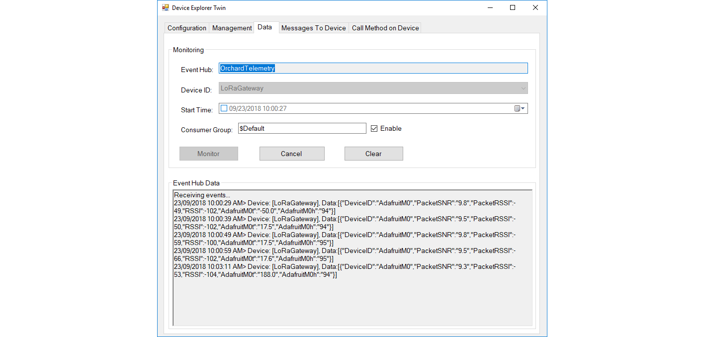
Then at my Azure IoT hub the data stream looked like this
AdaFruitM0LoRaFeatherIoTHub

To reduce power consumption I would disconnect/remove the light emitting diode(LED)