Windows 10 IoT Core triggered image upload to Azure Blob storage

Uploading the web camera images to Azure Storage was the next step.

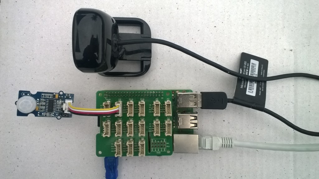
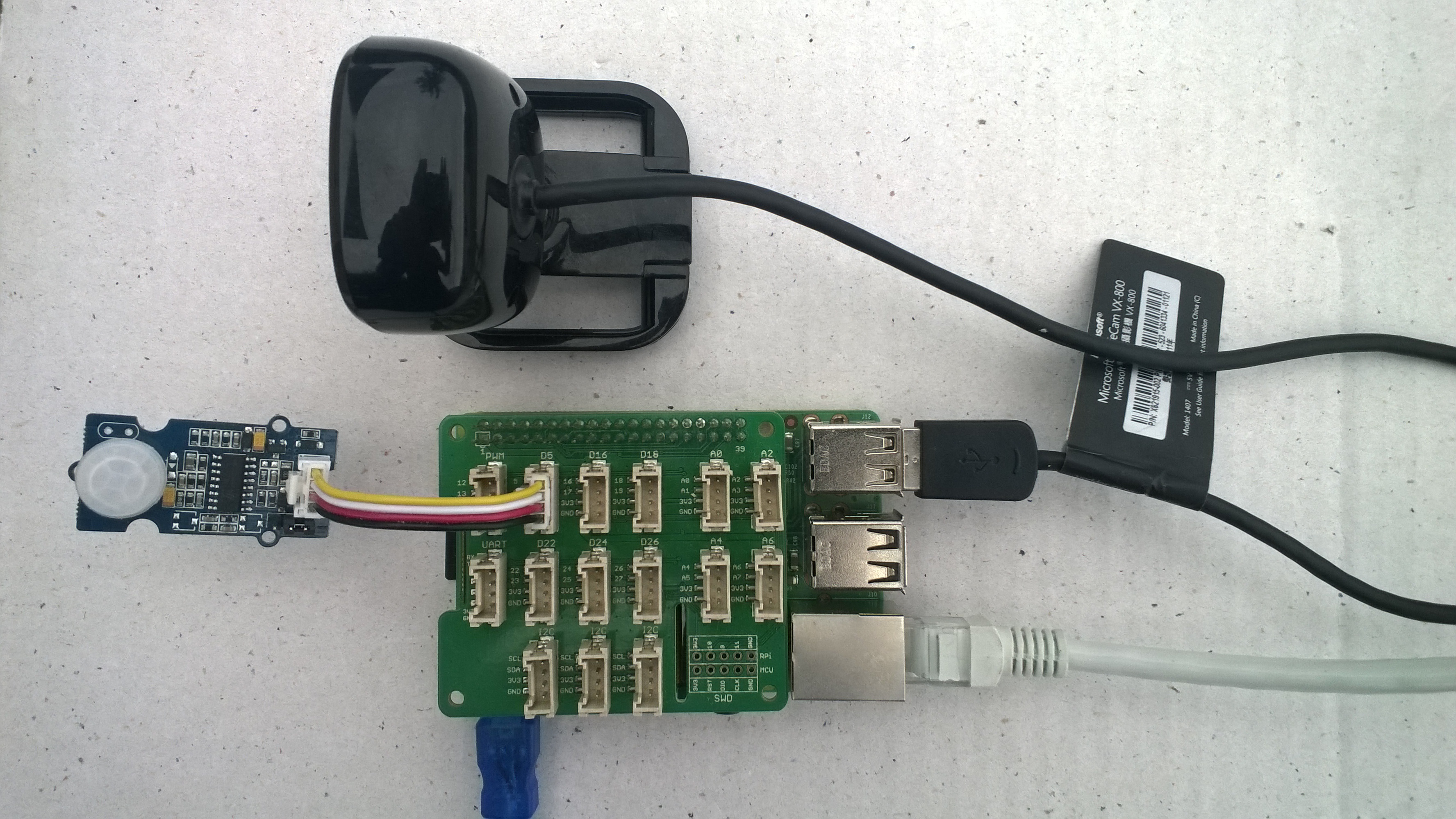
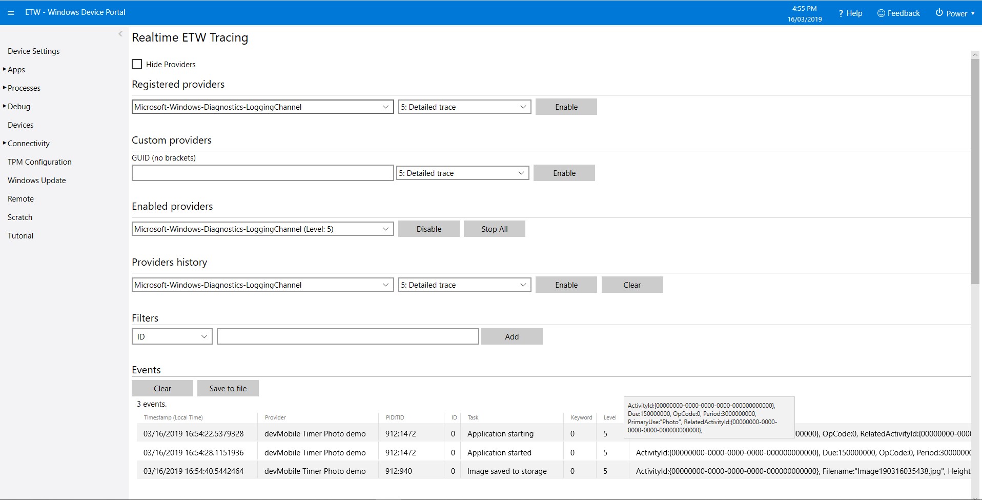
PIR Sensor trigger

For my test harness (in addition to a RaspberryPI & generic USB Web camera) I’m using some Seeedstudio Grove devices

While working on this code I realised I had made some invalid assumptions about the stream and the image properties so I refactored the code (which also made it simpler).

The Windows 10 IoT Core application has support for a JSON configuration file using Microsoft.Extensions.Configuration namespace functionality which took a bit of trial and error to get going.

IConfiguration configuration = new ConfigurationBuilder().
   AddJsonFile(localFolder.Path + @"\" + ConfigurationFilename, 
   false, 
   true).Build();

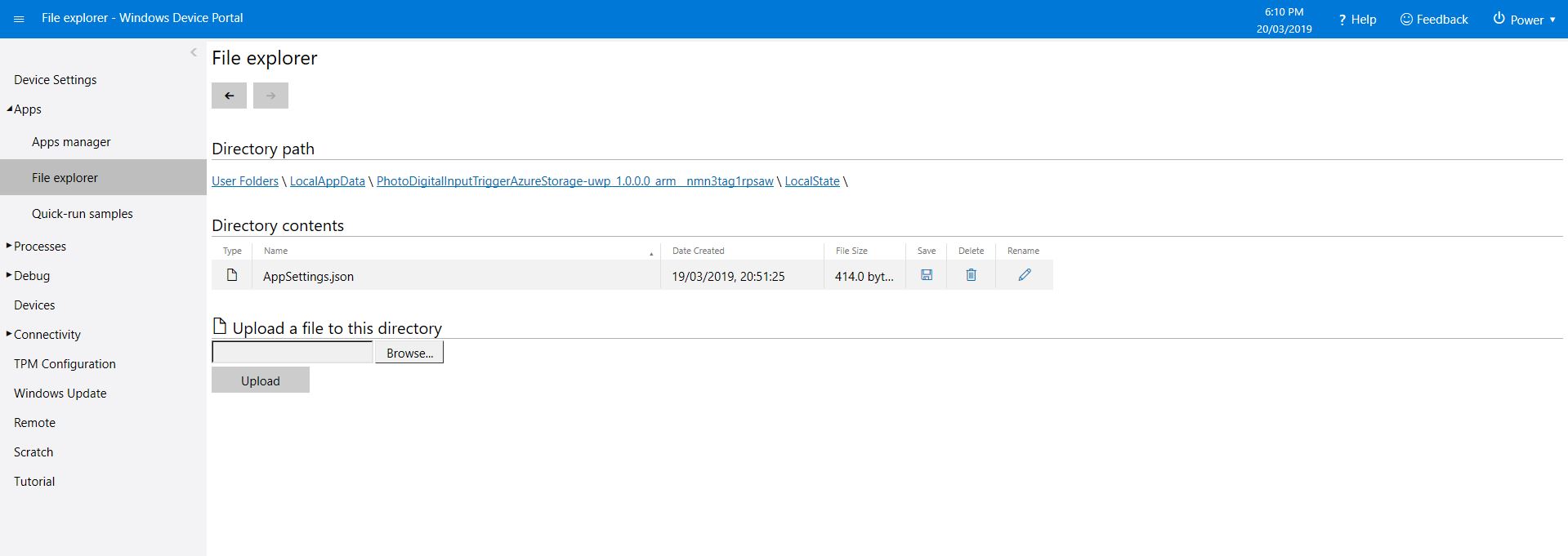
This gets the configuration subsystem to use the specified file in the application’s localstate folder. If there is no configuration file present i.e. the application has just been deployed for the first time or installed a template file is copied from the application install directory.

In the application configuration file you can specify the azure storage connection string, digital input port number, azure container name format (formatted machine name + Universal Coordinated Time(UTC)), the azure storage file name (formatted machine name + UTC) and the name of the file with the most recently uploaded image. These configuration settings are provided so that the image files can stored in “buckets” best suited to the way they are going to be processed.

{
  "AzureStorageConnectionString": "",
  "InterruptPinNumber": 5,
  "AzureContainerNameFormat": "{0}{1:yyMMdd}",
  "AzureImageFilenameFormat": "image{1:yyMMddHHmmss}.jpg",
  "AzureImageFilenameLatest": "latest.jpg"
} 

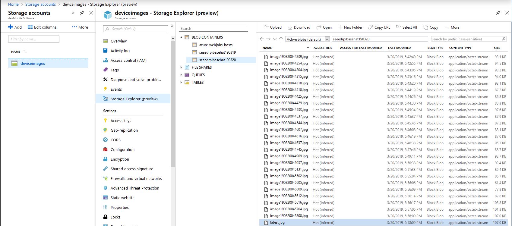
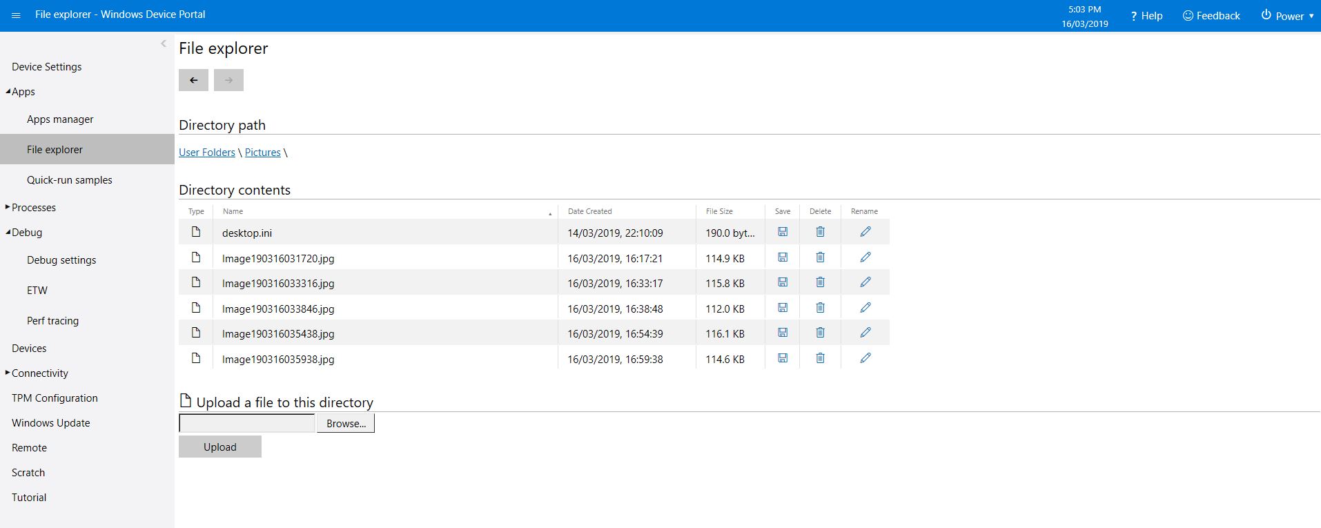
In my testing the pictures were stored in folders for each device/day and each image file had a timestamp in its name.

Azure Storage Explorer
/*
    Copyright ® 2019 March devMobile Software, All Rights Reserved
 
    MIT License
    ...
*/
namespace devMobile.Windows10IotCore.IoT.PhotoDigitalInputTriggerAzureStorage
{
	using System;
	using System.Diagnostics;

	using Microsoft.Extensions.Configuration;
	using Microsoft.WindowsAzure.Storage;
	using Microsoft.WindowsAzure.Storage.Blob;

	using Windows.ApplicationModel;
	using Windows.ApplicationModel.Background;
	using Windows.Devices.Gpio;
	using Windows.Foundation.Diagnostics;
	using Windows.Media.Capture;
	using Windows.Media.MediaProperties;
	using Windows.Storage;
	using Windows.System;

	public sealed class StartupTask : IBackgroundTask
	{
		private BackgroundTaskDeferral backgroundTaskDeferral = null;
		private readonly LoggingChannel logging = new LoggingChannel("devMobile Photo Digital Input Trigger Azure Storage demo", null, new Guid("4bd2826e-54a1-4ba9-bf63-92b73ea1ac4a"));
		private const string ConfigurationFilename = "appsettings.json";
		private GpioPin interruptGpioPin = null;
		private int interruptPinNumber;
		private MediaCapture mediaCapture;
		private string azureStorageConnectionString;
		private string azureStorageContainerNameFormat;
		private string azureStorageimageFilenameLatest;
		private string azureStorageImageFilenameFormat;
		private const string ImageFilenameLocal = "latest.jpg";
		private volatile bool cameraBusy = false;

		public void Run(IBackgroundTaskInstance taskInstance)
		{
			StorageFolder localFolder = ApplicationData.Current.LocalFolder;

			this.logging.LogEvent("Application starting");

			// Log the Application build, shield information etc.
			LoggingFields startupInformation = new LoggingFields();
			startupInformation.AddString("Timezone", TimeZoneSettings.CurrentTimeZoneDisplayName);
			startupInformation.AddString("OSVersion", Environment.OSVersion.VersionString);
			startupInformation.AddString("MachineName", Environment.MachineName);

			// This is from the application manifest 
			Package package = Package.Current;
			PackageId packageId = package.Id;
			PackageVersion version = packageId.Version;
			startupInformation.AddString("ApplicationVersion", string.Format($"{version.Major}.{version.Minor}.{version.Build}.{version.Revision}"));

			try
			{
				// see if the configuration file is present if not copy minimal sample one from application directory
				if (localFolder.TryGetItemAsync(ConfigurationFilename).AsTask().Result == null)
				{
					StorageFile templateConfigurationfile = Package.Current.InstalledLocation.GetFileAsync(ConfigurationFilename).AsTask().Result;
					templateConfigurationfile.CopyAsync(localFolder, ConfigurationFilename).AsTask();
					this.logging.LogMessage("JSON configuration file missing, templated created", LoggingLevel.Warning);
					return;
				}

				IConfiguration configuration = new ConfigurationBuilder().AddJsonFile(localFolder.Path + @"\" + ConfigurationFilename, false, true).Build();

				azureStorageConnectionString = configuration.GetSection("AzureStorageConnectionString").Value;
				startupInformation.AddString("AzureStorageConnectionString", azureStorageConnectionString);

				azureStorageContainerNameFormat = configuration.GetSection("AzureContainerNameFormat").Value;
				startupInformation.AddString("ContainerNameFormat", azureStorageContainerNameFormat);

				azureStorageImageFilenameFormat = configuration.GetSection("AzureImageFilenameFormat").Value;
				startupInformation.AddString("ImageFilenameFormat", azureStorageImageFilenameFormat);

				azureStorageimageFilenameLatest = configuration.GetSection("AzureImageFilenameLatest").Value;
				startupInformation.AddString("ImageFilenameLatest", azureStorageimageFilenameLatest);

				interruptPinNumber = int.Parse( configuration.GetSection("InterruptPinNumber").Value);
				startupInformation.AddInt32("Interrupt pin", interruptPinNumber);
			}
			catch (Exception ex)
			{
				this.logging.LogMessage("JSON configuration file load or settings retrieval failed " + ex.Message, LoggingLevel.Error);
				return;
			}

			try
			{
				mediaCapture = new MediaCapture();
				mediaCapture.InitializeAsync().AsTask().Wait();
			}
			catch (Exception ex)
			{
				this.logging.LogMessage("Camera configuration failed " + ex.Message, LoggingLevel.Error);
				return;
			}

			try
			{
				GpioController gpioController = GpioController.GetDefault();
				interruptGpioPin = gpioController.OpenPin(interruptPinNumber);
				interruptGpioPin.SetDriveMode(GpioPinDriveMode.InputPullUp);
				interruptGpioPin.ValueChanged += InterruptGpioPin_ValueChanged;
			}
			catch (Exception ex)
			{
				this.logging.LogMessage("Digital input configuration failed " + ex.Message, LoggingLevel.Error);
				return;
			}

			this.logging.LogEvent("Application started", startupInformation);

			//enable task to continue running in background
			backgroundTaskDeferral = taskInstance.GetDeferral();
		}

		private async void InterruptGpioPin_ValueChanged(GpioPin sender, GpioPinValueChangedEventArgs args)
		{
			DateTime currentTime = DateTime.UtcNow;
			Debug.WriteLine($"{DateTime.UtcNow.ToLongTimeString()} Digital Input Interrupt {sender.PinNumber} triggered {args.Edge}");

			if (args.Edge == GpioPinEdge.RisingEdge)
			{
				return;
			}

			// Just incase - stop code being called while photo already in progress
			if (cameraBusy)
			{
				return;
			}
			cameraBusy = true;

			try
			{
				StorageFile photoFile = await KnownFolders.PicturesLibrary.CreateFileAsync(ImageFilenameLocal, CreationCollisionOption.ReplaceExisting);
				ImageEncodingProperties imageProperties = ImageEncodingProperties.CreateJpeg();
				await mediaCapture.CapturePhotoToStorageFileAsync(imageProperties, photoFile);

				string azureContainername = string.Format(azureStorageContainerNameFormat, Environment.MachineName.ToLower(), currentTime);
				string azureStoragefilename = string.Format(azureStorageImageFilenameFormat, Environment.MachineName.ToLower(), currentTime);

				LoggingFields imageInformation = new LoggingFields();
				imageInformation.AddDateTime("TakenAtUTC", currentTime);
				imageInformation.AddString("LocalFilename", photoFile.Path);
				imageInformation.AddString("AzureContainerName", azureContainername);
				imageInformation.AddString("AzureStorageFilename", azureStoragefilename);
				imageInformation.AddString("AzureStorageFilenameLatest", azureStorageimageFilenameLatest);
				this.logging.LogEvent("Image saving to Azure storage", imageInformation);

				CloudStorageAccount storageAccount = CloudStorageAccount.Parse(azureStorageConnectionString);
				CloudBlobClient blobClient = storageAccount.CreateCloudBlobClient();

				CloudBlobContainer container = blobClient.GetContainerReference(azureContainername);
				await container.CreateIfNotExistsAsync();

				CloudBlockBlob blockBlob = container.GetBlockBlobReference(azureStoragefilename);
				await blockBlob.UploadFromFileAsync(photoFile);

				blockBlob = container.GetBlockBlobReference(azureStorageimageFilenameLatest);
				await blockBlob.UploadFromFileAsync(photoFile);

				this.logging.LogEvent("Image saved to Azure storage");
			}
			catch (Exception ex)
			{
				this.logging.LogMessage("Camera photo save or upload failed " + ex.Message, LoggingLevel.Error);
			}
			finally
			{
				cameraBusy = false;
			}
		}
	}
}

I need to add some code to ensure there is a minimum gap between photos and trial some different sensors. For example, an Adjustable Infrared Switch has proved to be a better option for some of my projects.

The code is available on GitHub and is a bit of a work in progress.

Windows 10 IoT Core image capture

Initiating image capture in response to a trigger was the next step, my plan is to use a button, or a proximity sensor like the passive infrared (PIR) module in the second image to trigger a photo.

Simple mechanical button trigger
PIR Sensor trigger

For my test rig (in addition to a RaspberryPI & generic USB Web camera) I’m using some Seeedstudio gear

The first step was to write an interrupt handler for the digital input, I figured triggering on the button push rather than release would make device more responsive.

/*
    Copyright ® 2019 Feb devMobile Software, All Rights Reserved
 
    MIT License
...
*/
namespace devMobile.Windows10IotCore.IoT.DigitalInputTrigger
{
	using System;
	using System.Diagnostics;
	using Windows.ApplicationModel.Background;
	using Windows.Devices.Gpio;

	public sealed class StartupTask : IBackgroundTask
	{
		private BackgroundTaskDeferral backgroundTaskDeferral = null;
		private GpioPin InterruptGpioPin = null;
		private const int InterruptPinNumber = 5;

		public void Run(IBackgroundTaskInstance taskInstance)
		{
			Debug.WriteLine("Application startup");

			try
			{
				GpioController gpioController = GpioController.GetDefault();

				InterruptGpioPin = gpioController.OpenPin(InterruptPinNumber);
				InterruptGpioPin.SetDriveMode(GpioPinDriveMode.InputPullUp);
				InterruptGpioPin.ValueChanged += InterruptGpioPin_ValueChanged;

				Debug.WriteLine("Digital Input Interrupt configuration success");
			}
			catch (Exception ex)
			{
				Debug.WriteLine($"Digital Input Interrupt configuration failed " + ex.Message);
				return;
			}

			//enable task to continue running in background
			backgroundTaskDeferral = taskInstance.GetDeferral();
		}

		private void InterruptGpioPin_ValueChanged(GpioPin sender, GpioPinValueChangedEventArgs args)
		{
			Debug.WriteLine($"{DateTime.UtcNow.ToLongTimeString()} Digital Input Interrupt {sender.PinNumber} triggered {args.Edge}");
		}
	}
}

Then I added in the camera functionality and made the interrupt handler async and await the camera and file system calls.

/*
    Copyright ® 2019 Feb devMobile Software, All Rights Reserved
 
    MIT License
...
*/
namespace devMobile.Windows10IotCore.IoT.PhotoDigitalInputTrigger
{
	using System;
	using System.Diagnostics;
	using Windows.ApplicationModel.Background;
	using Windows.Devices.Gpio;
	using Windows.Foundation.Diagnostics;
	using Windows.Media.Capture;
	using Windows.Media.MediaProperties;
	using Windows.Storage;

	public sealed class StartupTask : IBackgroundTask
	{
		private readonly LoggingChannel logging = new LoggingChannel("devMobile Photo Digital Input Trigger demo", null, new Guid("4bd2826e-54a1-4ba9-bf63-92b73ea1ac4a"));
		private BackgroundTaskDeferral backgroundTaskDeferral = null;
		private GpioPin InterruptGpioPin = null;
		private const int InterruptPinNumber = 5;
		private MediaCapture mediaCapture;
		private const string ImageFilenameFormat = "Image{0:yyMMddhhmmss}.jpg";
		private volatile bool CameraBusy = false;

		public void Run(IBackgroundTaskInstance taskInstance)
		{
			LoggingFields startupInformation = new LoggingFields();

			this.logging.LogEvent("Application starting");

			try
			{
				mediaCapture = new MediaCapture();
				mediaCapture.InitializeAsync().AsTask().Wait();
				Debug.WriteLine("Camera configuration success");

				GpioController gpioController = GpioController.GetDefault();

				InterruptGpioPin = gpioController.OpenPin(InterruptPinNumber);
				InterruptGpioPin.SetDriveMode(GpioPinDriveMode.InputPullUp);
				InterruptGpioPin.ValueChanged += InterruptGpioPin_ValueChanged;
				Debug.WriteLine("Digital Input Interrupt configuration success");
			}
			catch (Exception ex)
			{
				this.logging.LogMessage("Camera or digital input configuration failed " + ex.Message, LoggingLevel.Error);
				return;
			}

			startupInformation.AddString("PrimaryUse", mediaCapture.VideoDeviceController.PrimaryUse.ToString());
			startupInformation.AddInt32("Interrupt pin", InterruptPinNumber);

			this.logging.LogEvent("Application started", startupInformation);

			//enable task to continue running in background
			backgroundTaskDeferral = taskInstance.GetDeferral();
		}

		private async void InterruptGpioPin_ValueChanged(GpioPin sender, GpioPinValueChangedEventArgs args)
		{
			DateTime currentTime = DateTime.UtcNow;
			Debug.WriteLine($"{DateTime.UtcNow.ToLongTimeString()} Digital Input Interrupt {sender.PinNumber} triggered {args.Edge}");

			if (args.Edge == GpioPinEdge.RisingEdge)
			{
				return;
			}

			// Just incase - stop code being called while photo already in progress
			if (CameraBusy)
			{
				return;
			}
			CameraBusy = true;

			try
			{
				string filename = string.Format(ImageFilenameFormat, currentTime);

				IStorageFile photoFile = await KnownFolders.PicturesLibrary.CreateFileAsync(filename, CreationCollisionOption.ReplaceExisting);
				ImageEncodingProperties imageProperties = ImageEncodingProperties.CreateJpeg();
				await mediaCapture.CapturePhotoToStorageFileAsync(imageProperties, photoFile);

				LoggingFields imageInformation = new LoggingFields();

				imageInformation.AddDateTime("TakenAtUTC", currentTime);
				imageInformation.AddString("Filename", filename);
				imageInformation.AddString("Path", photoFile.Path);

				this.logging.LogEvent("Captured image saved to storage", imageInformation);
			}
			catch (Exception ex)
			{
				this.logging.LogMessage("Camera photo or save failed " + ex.Message, LoggingLevel.Error);
			}
			CameraBusy = false;
		}
	}
}

I found that contactor bounce was an issue (Grove- Touch Sensor OK) with larger mechanical buttons so I added the CameraBusy boolean flag to try and prevent re-entrancy problems. I’ll trial some other types of proximity and beam based on real-world student projects.

ETW logging or PIR triggered image capture

The code is available on GitHub and is a bit of a work in progress.

Windows 10 IoT Core image capture, upload and processing

One of my students wanted to do some image processing so to help her project along I am writing a series posts about capturing images on a Windows 10 IoT Core device. I’ll cover initiating the capturing of an image, uploading the image too Azure Blob storage, uploading the image to Azure blob storage associated with an Azure IoT Hub, then processing the images with the Azure Custom Vision Service.

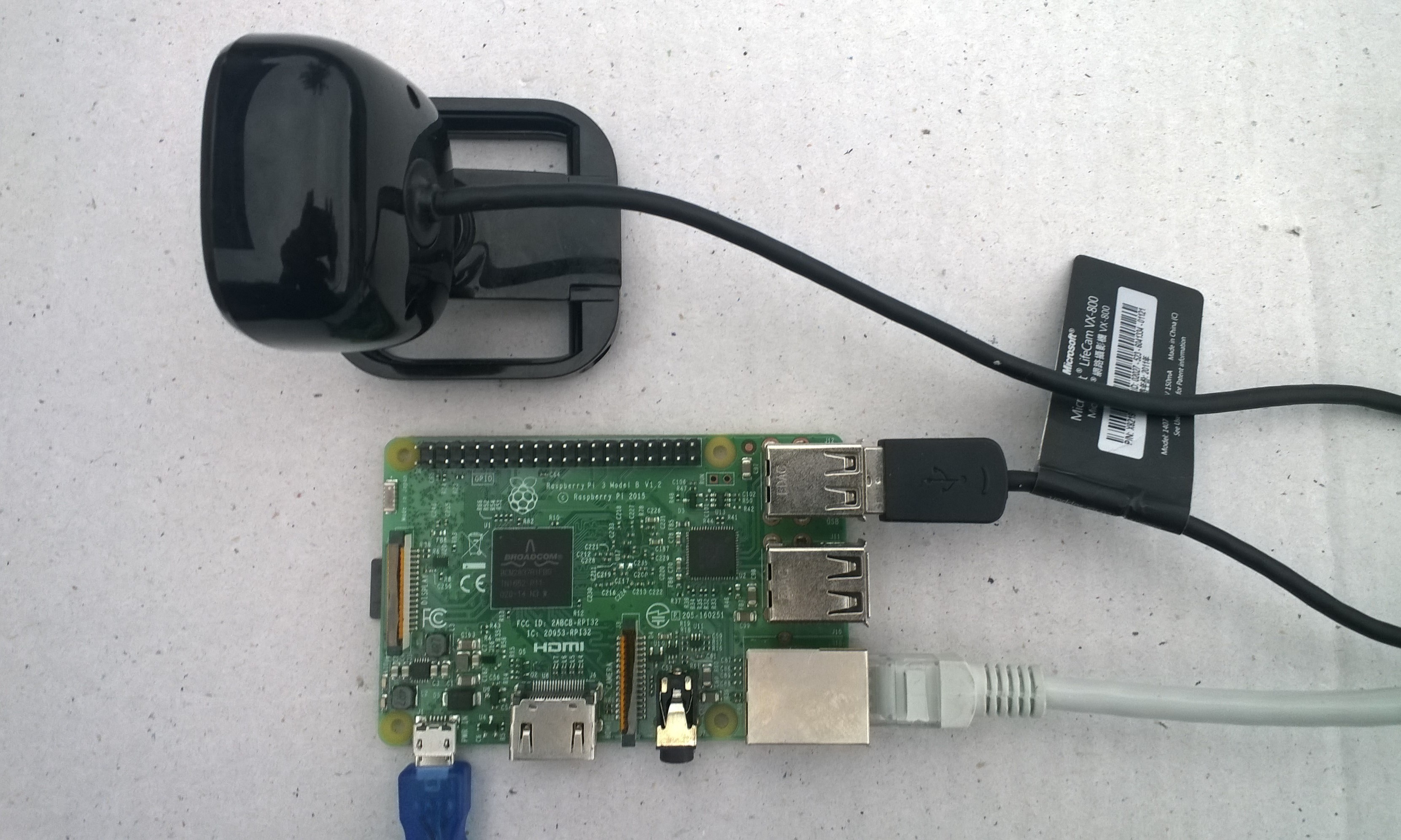
USB Camera test rig

First step was to capture an image from a USB web camera and store it in the local file system.

/*
    Copyright ® 2019 Feb devMobile Software, All Rights Reserved

    MIT License
…
*/
namespace devMobile.Windows10IotCore.IoT.PhotoTimer
{
	using System;
	using System.Threading;
	using Windows.ApplicationModel.Background;
	using Windows.Foundation.Diagnostics;
	using Windows.Media.Capture;
	using Windows.Media.MediaProperties;
	using Windows.Storage;

	public sealed class StartupTask : IBackgroundTask
	{
		private readonly LoggingChannel logging = new LoggingChannel("devMobile Timer Photo demo", null, new Guid("4bd2826e-54a1-4ba9-bf63-92b73ea1ac4a"));
		private BackgroundTaskDeferral backgroundTaskDeferral = null;
		private Timer ImageUpdatetimer;
		private readonly TimeSpan ImageUpdateDueDefault = new TimeSpan(0, 0, 15);
		private readonly TimeSpan ImageUpdatePeriodDefault = new TimeSpan(0, 5, 0);
		private MediaCapture mediaCapture;
		private const string ImageFilenameFormat = "Image{0:yyMMddhhmmss}.jpg";

		public void Run(IBackgroundTaskInstance taskInstance)
		{
			LoggingFields startupInformation = new LoggingFields();

			this.logging.LogEvent("Application starting");

			try
			{
				mediaCapture = new MediaCapture();
				mediaCapture.InitializeAsync().AsTask().Wait();

				ImageUpdatetimer = new Timer(ImageUpdateTimerCallback, null, ImageUpdateDueDefault, ImageUpdatePeriodDefault);

			}
			catch (Exception ex)
			{
				this.logging.LogMessage("Camera configuration failed " + ex.Message, LoggingLevel.Error);
				return;
			}

			startupInformation.AddString("PrimaryUse", mediaCapture.VideoDeviceController.PrimaryUse.ToString());
			startupInformation.AddTimeSpan("Due", ImageUpdateDueDefault);
			startupInformation.AddTimeSpan("Period", ImageUpdatePeriodDefault);

			this.logging.LogEvent("Application started", startupInformation);

			//enable task to continue running in background
			backgroundTaskDeferral = taskInstance.GetDeferral();
		}

		private void ImageUpdateTimerCallback(object state)
		{
			DateTime currentTime = DateTime.UtcNow;

			try
			{
				string filename = string.Format(ImageFilenameFormat, currentTime);

				IStorageFile photoFile = KnownFolders.PicturesLibrary.CreateFileAsync(filename, CreationCollisionOption.ReplaceExisting).AsTask().Result;
				ImageEncodingProperties imageProperties = ImageEncodingProperties.CreateJpeg();
				mediaCapture.CapturePhotoToStorageFileAsync(imageProperties, photoFile).AsTask().Wait();

				LoggingFields imageInformation = new LoggingFields();
				imageInformation.AddDateTime("TakenAtUTC", currentTime);
				imageInformation.AddString("Filename", filename);
				imageInformation.AddString("Path", photoFile.Path);
				this.logging.LogEvent("Image saved to storage", imageInformation);
			}
			catch (Exception ex)
			{
				this.logging.LogMessage("Image capture or save to local storage failed " + ex.Message, LoggingLevel.Error);
			}
		}
	}
}

To get my camera to work I had to enable “pictures library”, “microphone” and “webcam” in the capabilities section of the application manifest.

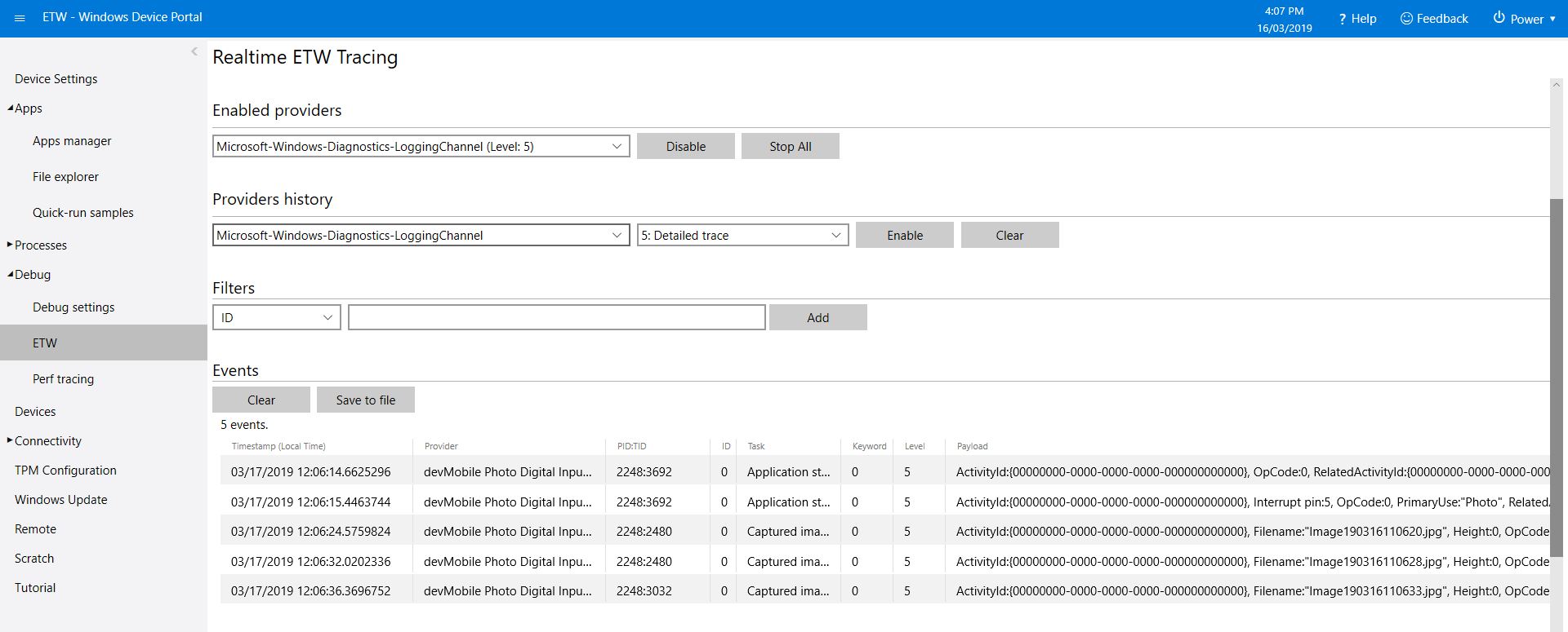
As the application starts up and captures images it logs information to the Windows 10 IoT Core ETW logging

Windows 10 IoT Core Portal ETW Logging
Camera images in \user folders\pictures

The code is available on GitHub and is a bit of a work in progress.

RFM9X.IoTCore Adafruit LoRa Radio Bonnet support

The RFM9X chip select line on the Adafruit LoRa Radio Bonnet 868 or 915MHz with OLED RFM95W is connected to pin 26(CS1), the reset line to pin 22(GPIO25) and the interrupt line to pin 15(GPIO22).

When I ran the RFM9XLoRaDeviceClient from my RFM9X.IoTCore library with the following configuration

#if ADAFRUIT_RADIO_BONNET
	private const byte ResetLine = 25;
	private const byte InterruptLine = 22;
	private Rfm9XDevice rfm9XDevice = new Rfm9XDevice(ChipSelectPin.CS1, ResetLine, InterruptLine);
#endif

public void Run(IBackgroundTaskInstance taskInstance)
{
	rfm9XDevice.Initialise(Frequency, paBoost: true, rxPayloadCrcOn : true);
#if DEBUG
	rfm9XDevice.RegisterDump();
#endif
	rfm9XDevice.OnReceive += Rfm9XDevice_OnReceive;
#if ADDRESSED_MESSAGES_PAYLOAD
	rfm9XDevice.Receive(UTF8Encoding.UTF8.GetBytes(Environment.MachineName));
#else
	rfm9XDevice.Receive();
#endif
	rfm9XDevice.OnTransmit += Rfm9XDevice_OnTransmit;

	Task.Delay(10000).Wait();

	while (true)
	{
		string messageText = string.Format("Hello from {0} ! {1}", Environment.MachineName, MessageCount);
		MessageCount -= 1;

		byte[] messageBytes = UTF8Encoding.UTF8.GetBytes(messageText);
		Debug.WriteLine("{0:HH:mm:ss}-TX {1} byte message {2}", DateTime.Now, messageBytes.Length, messageText);
#if ADDRESSED_MESSAGES_PAYLOAD
		this.rfm9XDevice.Send(UTF8Encoding.UTF8.GetBytes("AddressHere"), messageBytes);
#else
		this.rfm9XDevice.Send(messageBytes);
#endif
		Task.Delay(10000).Wait();
	}
}
#endif

I could see messages being sent and received in the debug output

Register 0x3e - Value 0X00 - Bits 00000000
Register 0x3f - Value 0X00 - Bits 00000000
Register 0x40 - Value 0X00 - Bits 00000000
Register 0x41 - Value 0X00 - Bits 00000000
Register 0x42 - Value 0X12 - Bits 00010010
...
The thread 0xec4 has exited with code 0 (0x0).
The thread 0x868 has exited with code 0 (0x0).
22:21:47-RX PacketSnr 9.8 Packet RSSI -80dBm RSSI -122dBm = 59 byte message "�LoRaIoT1Maduino2at 62.8,ah 77,wsa 1,wsg 3,wd 34.88,r 0.00,"
22:21:52-TX 31 byte message Hello from AdaFruitIOLoRa ! 255
22:21:52-TX Done
The thread 0xbf8 has exited with code 0 (0x0).
The program '[3380] backgroundTaskHost.exe' has exited with code -1 (0xffffffff).

Next step modify my Adafruit IO and Azure IoT Hub/Central field gateways.

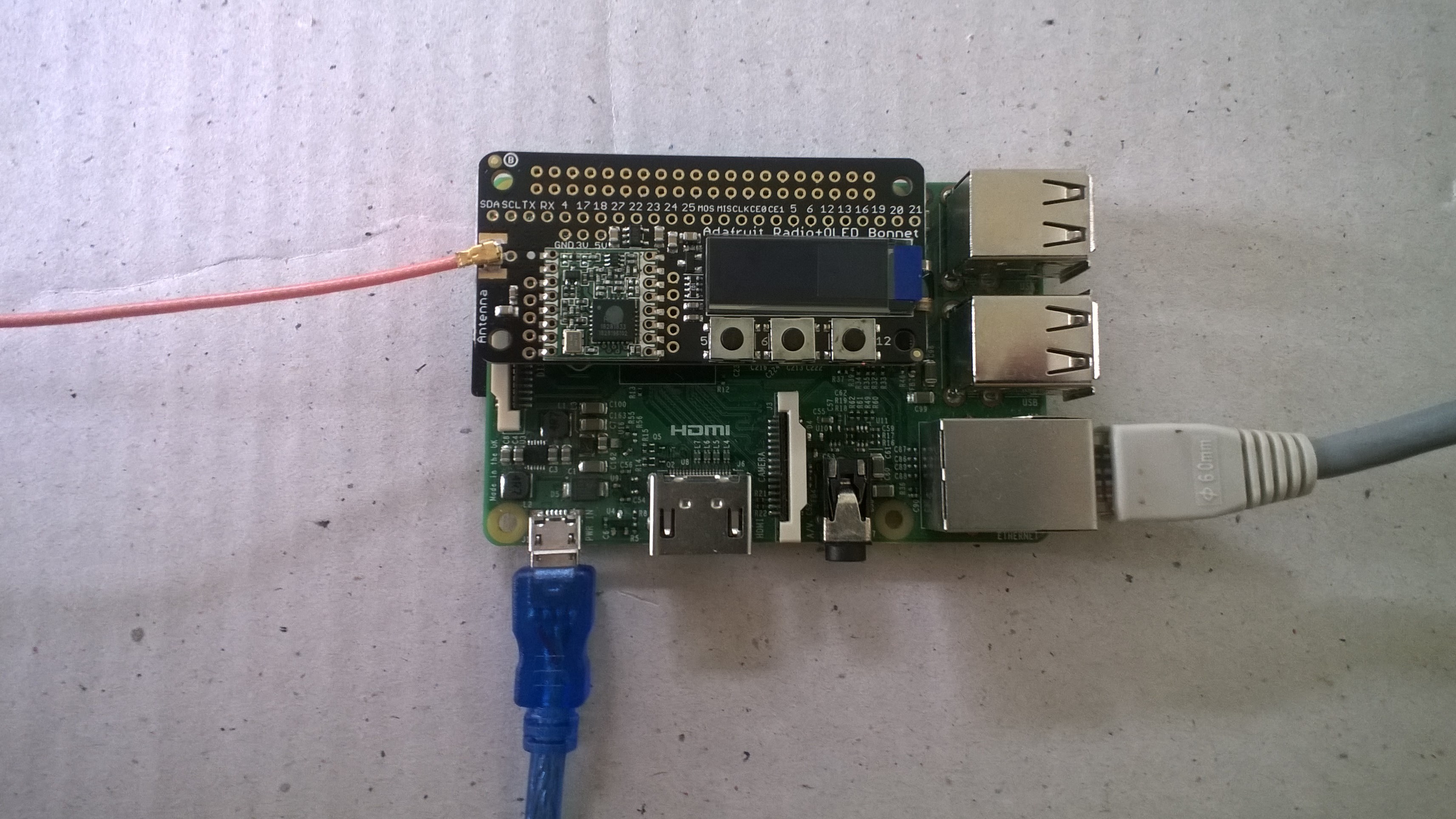
Adafruit LoRa Radio Bonnet with OLED – RadioFruit

Today a package arrived from Adafruit which contained an Adafruit LoRa Radio Bonnet 868 or 915MHz with OLED RFM95W.

The shield has a small OLED screen and 3 buttons connected to General Purpose Input Output(GPIO) pins.

The first step was to check the pin assignments of the 3 buttons.

/*
    Copyright ® 2019 Feb devMobile Software, All Rights Reserved
 
    MIT License

    Permission is hereby granted, free of charge, to any person obtaining a copy
    of this software and associated documentation files (the "Software"), to deal
    in the Software without restriction, including without limitation the rights
    to use, copy, modify, merge, publish, distribute, sublicense, and/or sell
    copies of the Software, and to permit persons to whom the Software is
    furnished to do so, subject to the following conditions:

    The above copyright notice and this permission notice shall be included in all
    copies or substantial portions of the Software.

    THE SOFTWARE IS PROVIDED "AS IS", WITHOUT WARRANTY OF ANY KIND, EXPRESS OR
    IMPLIED, INCLUDING BUT NOT LIMITED TO THE WARRANTIES OF MERCHANTABILITY,
    FITNESS FOR A PARTICULAR PURPOSE AND NONINFRINGEMENT. IN NO EVENT SHALL THE
    AUTHORS OR COPYRIGHT HOLDERS BE LIABLE FOR ANY CLAIM, DAMAGES OR OTHER
    LIABILITY, WHETHER IN AN ACTION OF CONTRACT, TORT OR OTHERWISE, ARISING FROM,
    OUT OF OR IN CONNECTION WITH THE SOFTWARE OR THE USE OR OTHER DEALINGS IN THE
    SOFTWARE

	 Adafruit documentation page
	 https://learn.adafruit.com/adafruit-radio-bonnets/pinouts

    Button 1: GPIO 5 
    Button 2: GPIO 6
    Button 3: GPIO 12 

 */
namespace devMobile.IoT.Rfm9x.AdafruitButtons
{
	using System;
	using System.Diagnostics;
	using Windows.ApplicationModel.Background;
	using Windows.Devices.Gpio;

	public sealed class StartupTask : IBackgroundTask
    {
		private BackgroundTaskDeferral backgroundTaskDeferral = null;
		private GpioPin InterruptGpioPin1 = null;
		private GpioPin InterruptGpioPin2 = null;
		private GpioPin InterruptGpioPin3 = null;
		private const int InterruptPinNumber1 = 5;
		private const int InterruptPinNumber2 = 6;
		private const int InterruptPinNumber3 = 12;
		private readonly TimeSpan debounceTimeout = new TimeSpan(0, 0, 15);


		public void Run(IBackgroundTaskInstance taskInstance)
        {
			Debug.WriteLine("Application startup");

			try
			{
				GpioController gpioController = GpioController.GetDefault();

				InterruptGpioPin1 = gpioController.OpenPin(InterruptPinNumber1);
				InterruptGpioPin1.SetDriveMode(GpioPinDriveMode.InputPullUp);
				InterruptGpioPin1.ValueChanged += InterruptGpioPin_ValueChanged; ;

				InterruptGpioPin2 = gpioController.OpenPin(InterruptPinNumber2);
				InterruptGpioPin2.SetDriveMode(GpioPinDriveMode.InputPullUp);
				InterruptGpioPin2.ValueChanged += InterruptGpioPin_ValueChanged; ;

				InterruptGpioPin3 = gpioController.OpenPin(InterruptPinNumber3);
				InterruptGpioPin3.SetDriveMode(GpioPinDriveMode.InputPullUp);
				InterruptGpioPin3.ValueChanged += InterruptGpioPin_ValueChanged; ;

				Debug.WriteLine("Digital Input Interrupt configuration success");
			}
			catch (Exception ex)
			{
				Debug.WriteLine($"Digital Input Interrupt configuration failed " + ex.Message);
				return;
			}

			//enable task to continue running in background
			backgroundTaskDeferral = taskInstance.GetDeferral();
		}

		private void InterruptGpioPin_ValueChanged(GpioPin sender, GpioPinValueChangedEventArgs args)
		{
			Debug.WriteLine($"Digital Input Interrupt {sender.PinNumber} triggered {args.Edge}");
		}
	}
}

When I ran the application it produced the following output when I pressed the three buttons (left->right) which confirmed I had the correct GPIO pins configuration.

Application startup
'backgroundTaskHost.exe' (CoreCLR: CoreCLR_UWP_Domain): Loaded 'C:\Data\Programs\WindowsApps\Microsoft.NET.CoreFramework.Debug.2.2_2.2.27129.1_arm__8wekyb3d8bbwe\System.Runtime.WindowsRuntime.dll'. Skipped loading symbols. Module is optimized and the debugger option 'Just My Code' is enabled.
Digital Input Interrupt configuration success
Digital Input Interrupt 5 triggered FallingEdge
Digital Input Interrupt 5 triggered RisingEdge
Digital Input Interrupt 6 triggered FallingEdge
Digital Input Interrupt 6 triggered RisingEdge
Digital Input Interrupt 12 triggered FallingEdge
Digital Input Interrupt 12 triggered RisingEdge

The next step was to get the Serial Peripheral Interface (SPI) interface for the module working.

/*
    Copyright ® 2019 Feb devMobile Software, All Rights Reserved
 
    MIT License

    Permission is hereby granted, free of charge, to any person obtaining a copy
    of this software and associated documentation files (the "Software"), to deal
    in the Software without restriction, including without limitation the rights
    to use, copy, modify, merge, publish, distribute, sublicense, and/or sell
    copies of the Software, and to permit persons to whom the Software is
    furnished to do so, subject to the following conditions:

    The above copyright notice and this permission notice shall be included in all
    copies or substantial portions of the Software.

    THE SOFTWARE IS PROVIDED "AS IS", WITHOUT WARRANTY OF ANY KIND, EXPRESS OR
    IMPLIED, INCLUDING BUT NOT LIMITED TO THE WARRANTIES OF MERCHANTABILITY,
    FITNESS FOR A PARTICULAR PURPOSE AND NONINFRINGEMENT. IN NO EVENT SHALL THE
    AUTHORS OR COPYRIGHT HOLDERS BE LIABLE FOR ANY CLAIM, DAMAGES OR OTHER
    LIABILITY, WHETHER IN AN ACTION OF CONTRACT, TORT OR OTHERWISE, ARISING FROM,
    OUT OF OR IN CONNECTION WITH THE SOFTWARE OR THE USE OR OTHER DEALINGS IN THE
    SOFTWARE

	 Adafruit documentation page
	 https://learn.adafruit.com/adafruit-radio-bonnets/pinouts

	 CS : CE1
	 RST : GPIO25
	 IRQ : GPIO22 (DIO0)
	 Unused : GPIO23 (DIO1)
	 Unused : GPIO24 (DIO2)
 */
namespace devMobile.IoT.Rfm9x.AdafruitSPI
{
	using System;
	using System.Diagnostics;
	using System.Threading;
	using Windows.ApplicationModel.Background;
	using Windows.Devices.Spi;

	public sealed class StartupTask : IBackgroundTask
	{
		public void Run(IBackgroundTaskInstance taskInstance)
		{
			SpiController spiController = SpiController.GetDefaultAsync().AsTask().GetAwaiter().GetResult();
			var settings = new SpiConnectionSettings(1)
			{
				ClockFrequency = 500000,
				Mode = SpiMode.Mode0,   // From SemTech docs pg 80 CPOL=0, CPHA=0
			};

			SpiDevice Device = spiController.GetDevice(settings);

			while (true)
			{
				byte[] writeBuffer = new byte[] { 0x42 }; // RegVersion
				byte[] readBuffer = new byte[1];

				Device.TransferSequential(writeBuffer, readBuffer);

				byte registerValue = readBuffer[0];
				Debug.WriteLine("Register 0x{0:x2} - Value 0X{1:x2} - Bits {2}", 0x42, registerValue, Convert.ToString(registerValue, 2).PadLeft(8, '0'));

				Thread.Sleep(10000);
			}
		}
	}
}

The output confirm the code worked

'backgroundTaskHost.exe' (CoreCLR: CoreCLR_UWP_Domain): Loaded 'C:\Data\Programs\WindowsApps\Microsoft.NET.CoreFramework.Debug.2.2_2.2.27129.1_arm__8wekyb3d8bbwe\System.Threading.Thread.dll'. Skipped loading symbols. Module is optimized and the debugger option 'Just My Code' is enabled.
Register 0x42 - Value 0X12 - Bits 00010010

The next step is to build support for this shield into my RFM9X.IoTCore library and get the OLED working.

Windows 10 IoT Core Field Gateways “less is more”

After looking back at the technical support interactions for my Azure IoT Hubs Windows 10 IoT Core Field Gateway & AdaFruit.IO LoRa Windows 10 IoT Core Field Gateway I think removing a “feature” might make it easier for first time users.

In an early version of the software I used to provide a sample configuration JSON file in the associated GitHub repository. Users had to download this file to a computer, update it with their Azure IOT Hub or Azure IoT Central connection string or AdafruitIO APIKey , frequency and device address, then upload to the field gateway.

In a later version of the software I added code which created an empty configuration file with defaults for all settings, many of which were a distraction as the majority of users would never change them.

More settings meant there was more scope for users to change settings which broke the device samples and the gateway.

I have removed the code to generate the full configuration file (starting with Azure IOT Hub field gateway) and included a sample configuration file with the minimum required settings in the GitHub repositories and installers.

I am assuming that if a user wants to change advanced settings they can look at the code and/or documentation and figure out the setting names and valid values.

The new sample configuration file for a Azure IoT Hub telemetry only gateway is

{
  "AzureIoTHubDeviceConnectionString": "Azure IOT Hub connection string",
  "AzureIoTHubTransportType": "amqp",
  "SensorIDIsDeviceIDSensorID": false,
  "Address": "Device address",
  "Frequency": 915000000.0
}

The prebuilt installers available on GitHub post version 1.0.13.0 (Azure IoT Hub) and 1.0.5.0 (Adafruit.IO) will implement this model.

Carbon Dioxide Sensor(MH-Z16) library comparison

The first library I looked at was for the DFRobot Gravity: UART Infrared CO2 Sensor (0-50000ppm). There was sample code provided on the associated wiki page. The code worked first time I ran it but I didn’t use this library due to the lack of checksum & packet header/footer validation.

/***************************************************
* Infrared CO2 Sensor 0-50000ppm(Wide Range)
* ****************************************************
* The follow example is used to detect CO2 concentration.
  
* @author lg.gang(lg.gang@qq.com)
* @version  V1.0
* @date  2016-6-6
  
* GNU Lesser General Public License.
* See <http://www.gnu.org/licenses/> for details.
* All above must be included in any redistribution
* ****************************************************/ 
#include <SoftwareSerial.h>
SoftwareSerial mySerial(10, 11); // RX, TX
unsigned char hexdata[9] = {0xFF,0x01,0x86,0x00,0x00,0x00,0x00,0x00,0x79}; //Read the gas density command /Don't change the order
void setup() {
  
  Serial.begin(9600);
  while (!Serial) {

  }
  mySerial.begin(9600);

}

void loop() {
   mySerial.write(hexdata,9);
   delay(500);

 for(int i=0,j=0;i<9;i++)
 {
  if (mySerial.available()>0)
  {
     long hi,lo,CO2;
     int ch=mySerial.read();

    if(i==2){     hi=ch;   }   //High concentration
    if(i==3){     lo=ch;   }   //Low concentration
    if(i==8) {
               CO2=hi*256+lo;  //CO2 concentration
      Serial.print("CO2 concentration: ");
      Serial.print(CO2);
      Serial.println("ppm");      
      }
    }   
  } 
}

After some GitHub searching the second library I looked at was abbozza_CO2_MHZ16_arduino by Michael Brinkmeier. This library appears to be “plug-in” module for the abbozza! framework. I didn’t use this library due to the lack of checksum & packet header/footer validation.

/**
 * @license
 * abbozza! Calliope plugin for the MH-Z16 CO2 sensor
 * 
 * The sensor has to be connected to a serial connection with 9600 baud.
 *
 * Copyright 2015 Michael Brinkmeier ( michael.brinkmeier@uni-osnabrueck.de )
 *
 * Licensed under the Apache License, Version 2.0 (the "License");
 * you may not use this file except in compliance with the License.
 * You may obtain a copy of the License at
 *
 *   http://www.apache.org/licenses/LICENSE-2.0
 *
 * Unless required by applicable law or agreed to in writing, software
 * distributed under the License is distributed on an "AS IS" BASIS,
 * WITHOUT WARRANTIES OR CONDITIONS OF ANY KIND, either express or implied.
 * See the License for the specific language governing permissions and
 * limitations under the License.
 */

#include "SoftwareSerial.h"
#include "MHZ16.h"
#include "Arduino.h"

MHZ16::MHZ16(int tx, int rx) {
    this->serial = new SoftwareSerial(rx,tx,false);
    this->serial->begin(9600);
}


void MHZ16::calibrate() {
    int idx;
    for (idx = 0; idx < 9; idx++) {
        serial->write(cal[idx]);
    }
    delay(10);
}

void MHZ16::doMeasurement() {
    int idx;
    int bu;

    for (idx = 0; idx < 9; idx++) {
        serial->write(cmd[idx]);
    }
    delay(10);

    while (serial->available()) {
        do {
            bu = serial->read();
        } while (bu != 255);
        buf[0] = bu;

        idx = 1;
        while (serial->available() && (idx < 9)) {
            bu = serial->read();
            buf[idx] = bu;
            idx++;
        }

        if (idx == 9) {
            PPM = ((int) buf[2]) *256 + ((int) buf[3]);
        }
    }
}

int MHZ16::getPPM() {
    return PPM;
}

The third library was produced by Sandbox electronics for their selection of 10,000PPM thru 100,000PPM MH-Z16 sensors. Their datasheet looked similar(maybe newer?) to the Seeedstudio one and the packet format was the same.

Their library had checksum & packet header/footer validation but I didn’t use it because the carbon dioxide concentration was calculated using 4 bytes (maybe this was to support the different range sensors?)

/*
Description:
This is a example code for Sandbox Electronics NDIR CO2 sensor module.
You can get one of those products on
http://sandboxelectronics.com

Version:
V1.2

Release Date:
2019-01-10

Author:
Tiequan Shao          support@sandboxelectronics.com

Lisence:
CC BY-NC-SA 3.0

Please keep the above information when you use this code in your project.
*/

#include <SoftwareSerial.h>
#include <NDIR_SoftwareSerial.h>
#define  RECEIVE_TIMEOUT  (100)

#if ARDUINO >= 100
    #include "Arduino.h"
#else
    #include "WProgram.h"
#endif

class SoftwareSerial;

uint8_t NDIR_SoftwareSerial::cmd_measure[9]                = {0xFF,0x01,0x9C,0x00,0x00,0x00,0x00,0x00,0x63};
uint8_t NDIR_SoftwareSerial::cmd_calibrateZero[9]          = {0xFF,0x01,0x87,0x00,0x00,0x00,0x00,0x00,0x78};
uint8_t NDIR_SoftwareSerial::cmd_enableAutoCalibration[9]  = {0xFF,0x01,0x79,0xA0,0x00,0x00,0x00,0x00,0xE6};
uint8_t NDIR_SoftwareSerial::cmd_disableAutoCalibration[9] = {0xFF,0x01,0x79,0x00,0x00,0x00,0x00,0x00,0x86};

NDIR_SoftwareSerial::NDIR_SoftwareSerial(uint8_t rx_pin, uint8_t tx_pin) : serial(rx_pin, tx_pin, false)
{
}


uint8_t NDIR_SoftwareSerial::begin()
{
    serial.begin(9600);

    if (measure()) {
        return true;
    } else {
        return false;
    }
}

uint8_t NDIR_SoftwareSerial::measure()
{
    uint8_t i;
    uint8_t buf[9];
    uint32_t start = millis();

    serial.flush();

    for (i=0; i<9; i++) {
        serial.write(cmd_measure[i]);
    }

    for (i=0; i<9;) {
        if (serial.available()) {
            buf[i++] = serial.read();
        }

        if (millis() - start > RECEIVE_TIMEOUT) {
            return false;
        }
    }

    if (parse(buf)) {
        return true;
    }

    return false;
}


void NDIR_SoftwareSerial::calibrateZero()
{
    uint8_t i;

    for (i=0; i<9; i++) {
        serial.write(cmd_calibrateZero[i]);
    }
}


void NDIR_SoftwareSerial::enableAutoCalibration()
{
    uint8_t i;

    for (i=0; i<9; i++) {
        serial.write(cmd_enableAutoCalibration[i]);
    }
}


void NDIR_SoftwareSerial::disableAutoCalibration()
{
    uint8_t i;

    for (i=0; i<9; i++) {
        serial.write(cmd_disableAutoCalibration[i]);
    }
}


uint8_t NDIR_SoftwareSerial::parse(uint8_t *pbuf)
{
    uint8_t i;
    uint8_t checksum = 0;

    for (i=0; i<9; i++) {
        checksum += pbuf[i];
    }

    if (pbuf[0] == 0xFF && pbuf[1] == 0x9C && checksum == 0xFF) {
        ppm = (uint32_t)pbuf[2] << 24 | (uint32_t)pbuf[3] << 16 | (uint32_t)pbuf[4] << 8 | pbuf[5];
        return true;
    } else {
        return false;
    }
}

The forth library I looked at was MHZ-Z-C02-Sensors by Tobias Schürg this library was for different series of MHZ sensors. With re-synching, configurable timeouts and checksum validation it looked like the code could easily be adapted for the MH-Z16.

/* MHZ library

    By Tobias Schürg
*/

#include "MHZ.h"

const int MHZ14A = 14;
const int MHZ19B = 19;

const int MHZ14A_RESPONSE_TIME = 60;
const int MHZ19B_RESPONSE_TIME = 120;

const int STATUS_NO_RESPONSE = -2;
const int STATUS_CHECKSUM_MISMATCH = -3;
const int STATUS_INCOMPLETE = -4;
const int STATUS_NOT_READY = -5;

unsigned long lastRequest = 0;

MHZ::MHZ(uint8_t rxpin, uint8_t txpin, uint8_t pwmpin, uint8_t type)
    : co2Serial(rxpin, txpin) {
  _rxpin = rxpin;
  _txpin = txpin;
  _pwmpin = pwmpin;
  _type = type;

  co2Serial.begin(9600);
}

/**
 * Enables or disables the debug mode (more logging).
 */
void MHZ::setDebug(boolean enable) {
  debug = enable;
  if (debug) {
    Serial.println(F("MHZ: debug mode ENABLED"));
  } else {
    Serial.println(F("MHZ: debug mode DISABLED"));
  }
}

boolean MHZ::isPreHeating() {
  if (_type == MHZ14A) {
    return millis() < (3 * 60 * 1000);
  } else if (_type == MHZ19B) {
    return millis() < (3 * 60 * 1000);
  } else {
    Serial.println(F("MHZ::isPreHeating() => UNKNOWN SENSOR"));
    return false;
  }
}

boolean MHZ::isReady() {
  if (isPreHeating()) return false;
  if (_type == MHZ14A)
    return lastRequest < millis() - MHZ14A_RESPONSE_TIME;
  else if (_type == MHZ19B)
    return lastRequest < millis() - MHZ19B_RESPONSE_TIME;
  else {
    Serial.print(F("MHZ::isReady() => UNKNOWN SENSOR \""));
    Serial.print(_type);
    Serial.println(F("\""));
    return true;
  }
}

int MHZ::readCO2UART() {
  if (!isReady()) return STATUS_NOT_READY;
  if (debug) Serial.println(F("-- read CO2 uart ---"));
  byte cmd[9] = {0xFF, 0x01, 0x86, 0x00, 0x00, 0x00, 0x00, 0x00, 0x79};
  byte response[9];  // for answer

  if (debug) Serial.print(F("  >> Sending CO2 request"));
  co2Serial.write(cmd, 9);  // request PPM CO2
  lastRequest = millis();

  // clear the buffer
  memset(response, 0, 9);

  int waited = 0;
  while (co2Serial.available() == 0) {
    if (debug) Serial.print(".");
    delay(100);  // wait a short moment to avoid false reading
    if (waited++ > 10) {
      if (debug) Serial.println(F("No response after 10 seconds"));
      co2Serial.flush();
      return STATUS_NO_RESPONSE;
    }
  }
  if (debug) Serial.println();

  // The serial stream can get out of sync. The response starts with 0xff, try
  // to resync.
  // TODO: I think this might be wrong any only happens during initialization?
  boolean skip = false;
  while (co2Serial.available() > 0 && (unsigned char)co2Serial.peek() != 0xFF) {
    if (!skip) {
      Serial.print(F("MHZ: - skipping unexpected readings:"));
      skip = true;
    }
    Serial.print(" ");
    Serial.print(co2Serial.peek(), HEX);
    co2Serial.read();
  }
  if (skip) Serial.println();

  if (co2Serial.available() > 0) {
    int count = co2Serial.readBytes(response, 9);
    if (count < 9) {
      co2Serial.flush();
      return STATUS_INCOMPLETE;
    }
  } else {
    co2Serial.flush();
    return STATUS_INCOMPLETE;
  }

  if (debug) {
    // print out the response in hexa
    Serial.print(F("  << "));
    for (int i = 0; i < 9; i++) {
      Serial.print(response[i], HEX);
      Serial.print(F("  "));
    }
    Serial.println(F(""));
  }

  // checksum
  byte check = getCheckSum(response);
  if (response[8] != check) {
    Serial.println(F("MHZ: Checksum not OK!"));
    Serial.print(F("MHZ: Received: "));
    Serial.println(response[8], HEX);
    Serial.print(F("MHZ: Should be: "));
    Serial.println(check, HEX);
    temperature = STATUS_CHECKSUM_MISMATCH;
    co2Serial.flush();
    return STATUS_CHECKSUM_MISMATCH;
  }

  int ppm_uart = 256 * (int)response[2] + response[3];

  temperature = response[4] - 44;  // - 40;

  byte status = response[5];
  if (debug) {
    Serial.print(F(" # PPM UART: "));
    Serial.println(ppm_uart);
    Serial.print(F(" # Temperature? "));
    Serial.println(temperature);
  }

  // Is always 0 for version 14a  and 19b
  // Version 19a?: status != 0x40
  if (debug && status != 0) {
    Serial.print(F(" ! Status maybe not OK ! "));
    Serial.println(status, HEX);
  } else if (debug) {
    Serial.print(F(" Status  OK: "));
    Serial.println(status, HEX);
  }

  co2Serial.flush();
  return ppm_uart;
}

uint8_t MHZ::getLastTemperature() {
  if (isPreHeating()) return STATUS_NOT_READY;
  return temperature;
}

byte MHZ::getCheckSum(byte* packet) {
  if (debug) Serial.println(F("  getCheckSum()"));
  byte i;
  unsigned char checksum = 0;
  for (i = 1; i < 8; i++) {
    checksum += packet[i];
  }
  checksum = 0xff - checksum;
  checksum += 1;
  return checksum;
}

int MHZ::readCO2PWM() {
  // if (!isReady()) return STATUS_NOT_READY; not needed?
  if (debug) Serial.print(F("-- reading CO2 from pwm "));
  unsigned long th, tl, ppm_pwm = 0;
  do {
    if (debug) Serial.print(".");
    th = pulseIn(_pwmpin, HIGH, 1004000) / 1000;
    tl = 1004 - th;
    ppm_pwm = 5000 * (th - 2) / (th + tl - 4);
  } while (th == 0);
  if (debug) {
    Serial.print(F("\n # PPM PWM: "));
    Serial.println(ppm_pwm);
  }
  return ppm_pwm;
}

The forth library I looked at was MHZ16_uart by Intar it had been updated recently, was quite lightweight, had timeouts, checksum & packet header/footer validation.

/*
  MHZ16_uart.cpp - MH-Z16 CO2 sensor library for ESP-32
  by Intar BV
  version 0.1
  
  License MIT
*/

#include "MHZ16_uart.h"
#include "Arduino.h"


#define WAIT_READ_TIMES	100
#define WAIT_READ_DELAY	10

// public

MHZ16_uart::MHZ16_uart(){
}
MHZ16_uart::MHZ16_uart(int rx, int tx){
	begin(rx,tx);
}

MHZ16_uart::~MHZ16_uart(){
}

#ifdef ARDUINO_ARCH_ESP32
void MHZ16_uart::begin(int rx, int tx, int s){
	_rx_pin = rx;
	_tx_pin = tx;
	_start_millis = millis();
	_serialno = s;
}
#else
void MHZ16_uart::begin(int rx, int tx){
	_rx_pin = rx;
	_start_millis = millis();
	_tx_pin = tx;
}
#endif

void MHZ16_uart::calibrateZero() {
	writeCommand( zerocalib );
}

void MHZ16_uart::calibrateSpan(int ppm) {
	if( ppm < 1000 )	return;

	uint8_t com[MHZ16_uart::REQUEST_CNT];
	for(int i=0; i<MHZ16_uart::REQUEST_CNT; i++) {
		com[i] = spancalib[i];
	}
	com[3] = (uint8_t)(ppm/256);
	com[4] = (uint8_t)(ppm%256);
	writeCommand( com );
}

int MHZ16_uart::getPPM() {
	return getSerialData();
}

boolean MHZ16_uart::isWarming(){
	return millis() <= _start_millis + PREHEAT_MS;
}

//protected
void MHZ16_uart::writeCommand(uint8_t cmd[]) {
	writeCommand(cmd,NULL);
}

void MHZ16_uart::writeCommand(uint8_t cmd[], uint8_t* response) {
#ifdef ARDUINO_ARCH_ESP32
	HardwareSerial hserial(_serialno);
	hserial.begin(9600, SERIAL_8N1, _rx_pin, _tx_pin);
#else
	SoftwareSerial hserial(_rx_pin, _tx_pin);
	hserial.begin(9600);
#endif
    hserial.write(cmd, REQUEST_CNT);
	hserial.write(MHZ16_checksum(cmd));
	hserial.flush();
	
	if (response != NULL) {
		int i = 0;
		while(hserial.available() <= 0) {
			if( ++i > WAIT_READ_TIMES ) {
				Serial.println("error: can't get MH-Z16 response.");
				return;
			}
			yield();
			delay(WAIT_READ_DELAY);
		}
		hserial.readBytes(response, MHZ16_uart::RESPONSE_CNT);
	}

}

//private

int MHZ16_uart::getSerialData() {
	uint8_t buf[MHZ16_uart::RESPONSE_CNT];
	for( int i=0; i<MHZ16_uart::RESPONSE_CNT; i++){
		buf[i]=0x0;
	}

	writeCommand(getppm, buf);
	int co2 = 0, co2temp = 0, co2status =  0;

	// parse
	if (buf[0] == 0xff && buf[1] == 0x86 && MHZ16_checksum(buf) == buf[MHZ16_uart::RESPONSE_CNT-1]) {
		co2 = buf[2] * 256 + buf[3];
	} else {
		co2 = co2temp = co2status = -1;
	}
	return co2;
}	

uint8_t MHZ16_uart::MHZ16_checksum( uint8_t com[] ) {
	uint8_t sum = 0x00;
	for ( int i = 1; i < MHZ16_uart::REQUEST_CNT; i++) {
		sum += com[i];
	}
	sum = 0xff - sum + 0x01;
	return sum;
}

It ran second time on one of my Arduino devices (after I figured out how to configure the serial port pins) and though intended for an ESP8266 device this is the library I will field test.

#include <MHZ16_uart.h>

//Select 2 digital pins as SoftwareSerial's Rx and Tx. For example, Rx=2 Tx=3
MHZ16_uart mySensor(4,5);

void setup()
{
  Serial.begin(9600);

  mySensor.begin(4,5); 
}


void loop() 
{
  if ( !mySensor.isWarming())
  {
    Serial.print("CO2 Concentration is ");
    Serial.print(mySensor.getPPM());
    Serial.println("ppm");
  }
  else
{
    Serial.println("isWarming");
  }
  
  delay(10000);
}

This was just a sample of the libraries I found on GitHub if I missed a good a library contact me via the comments.

Grove – Carbon Dioxide Sensor(MH-Z16) trial

In preparation for a student project to monitor the CO2 levels in a number of classrooms I purchased a Grove – Carbon Dioxide Sensor(MH-Z16) for evaluation.


Arduino Uno R3 and CO2 Sensor

I downloaded the seeedstudio wiki example code, compiled and uploaded it to one of my Arduino Uno R3 devices.

I increased delay between readings to 10sec and reduced the baud rate of the serial logging to 9600baud.

/*
  This test code is write for Arduino AVR Series(UNO, Leonardo, Mega)
  If you want to use with LinkIt ONE, please connect the module to D0/1 and modify:

  // #include <SoftwareSerial.h>
  // SoftwareSerial s_serial(2, 3);      // TX, RX

  #define sensor Serial1
*/


#include <SoftwareSerial.h>
SoftwareSerial s_serial(2, 3);      // TX, RX

#define sensor s_serial

const unsigned char cmd_get_sensor[] =
{
    0xff, 0x01, 0x86, 0x00, 0x00,
    0x00, 0x00, 0x00, 0x79
};

unsigned char dataRevice[9];
int temperature;
int CO2PPM;

void setup()
{
    sensor.begin(9600);
    Serial.begin(9600);
    Serial.println("get a 'g', begin to read from sensor!");
    Serial.println("********************************************************");
    Serial.println();
}

void loop()
{
    if(dataRecieve())
    {
        Serial.print("Temperature: ");
        Serial.print(temperature);
        Serial.print("  CO2: ");
        Serial.print(CO2PPM);
        Serial.println("");
    }
    delay(10000);
}

bool dataRecieve(void)
{
    byte data[9];
    int i = 0;

    //transmit command data
    for(i=0; i<sizeof(cmd_get_sensor); i++)
    {
        sensor.write(cmd_get_sensor[i]);
    }
    delay(10);
    //begin reveiceing data
    if(sensor.available())
    {
        while(sensor.available())
        {
            for(int i=0;i<9; i++)
            {
                data[i] = sensor.read();
            }
        }
    }

    for(int j=0; j<9; j++)
    {
        Serial.print(data[j]);
        Serial.print(" ");
    }
    Serial.println("");

    if((i != 9) || (1 + (0xFF ^ (byte)(data[1] + data[2] + data[3] + data[4] + data[5] + data[6] + data[7]))) != data[8])
    {
        return false;
    }

    CO2PPM = (int)data[2] * 256 + (int)data[3];
    temperature = (int)data[4] - 40;

    return true;
}

The debug output wasn’t too promising there weren’t any C02 parts per million (ppm) values and the response payloads looked wrong. So I downloaded the MH-Z16 NDIR CO2 Sensor datasheet for some background. The datasheet didn’t mention any temperature data in the message payloads so I removed that code.

The response payload validation code was all on one line and hard to figure out what it was doing.

    if((i != 9) || (1 + (0xFF ^ (byte)(data[1] + data[2] + data[3] + data[4] + data[5] + data[6] + data[7]))) != data[8])
    {
        return false;
    }

To make debugging easier I split the payload validation code into several steps so I could see what was failing.

/*
  This test code is write for Arduino AVR Series(UNO, Leonardo, Mega)
  If you want to use with LinkIt ONE, please connect the module to D0/1 and modify:

  // #include <SoftwareSerial.h>
  // SoftwareSerial s_serial(2, 3);      // TX, RX

  #define sensor Serial1
*/


#include <SoftwareSerial.h>
SoftwareSerial s_serial(2, 3);      // TX, RX

#define sensor s_serial

const unsigned char cmd_get_sensor[] =
{
    0xff, 0x01, 0x86, 0x00, 0x00,
    0x00, 0x00, 0x00, 0x79
};

unsigned char dataRevice[9];
int CO2PPM;

void setup()
{
    sensor.begin(9600);
    Serial.begin(9600);
    Serial.println("get a 'g', begin to read from sensor!");
    Serial.println("********************************************************");
    Serial.println();
}

void loop()
{
    if(dataRecieve())
    {
        Serial.print("  CO2: ");
        Serial.print(CO2PPM);
        Serial.println("");
    }
    delay(10000);
}

bool dataRecieve(void)
{
    byte data[9];
    int i = 0;

    //transmit command data
    for(i=0; i<sizeof(cmd_get_sensor); i++)
    {
        sensor.write(cmd_get_sensor[i]);
    }
    delay(10);
    //begin reveiceing data
    if(sensor.available())
    {
        while(sensor.available())
        {
            for(int i=0;i<9; i++)
            {
                data[i] = sensor.read();
            }
        }
    }

    for(int j=0; j<9; j++)
    {
        Serial.print(data[j]);
        Serial.print(" ");
    }
    Serial.println("");

    // First calculate then validate the check sum as there is no point in proceeding if the packet is corrupted. (code inspired by datasheet algorithm)
    byte checksum = 0 ;
    for(int j=1; j<8; j++)
    {
      checksum += data[j];
    }
    checksum=0xff-checksum; 
    checksum+=1;
       
    if  (checksum != data[8])
    {
      Serial.println("Error checksum");
      return false;
    }

    // Then check the start byte to make sure response is what we were expecting
    if ( data[0] != 0xFF )
    {
        Serial.println("Error start byte");
        return false;
    }

    // Then check the command byte to make sure response is what we were expecting
    if ( data[1] != 0x86 )
    {
        Serial.println("Error command");
        return false;
    }


    CO2PPM = (int)data[2] * 256 + (int)data[3];

    return true;
}

From these modifications I could see the payload was messed up and based on the datasheet message descriptions it looked like it was offset by a byte or two.

15:58:32.509 -> get a 'g', begin to read from sensor!
15:58:32.578 -> ********************************************************
15:58:32.612 -> 
15:58:32.612 -> 255 134 6 238 76 0 0 1 255 
15:58:32.647 -> Error checksum
15:58:42.631 -> 57 255 134 6 246 76 0 0 1 
15:58:42.666 -> Error checksum
15:58:52.667 -> 49 255 134 5 125 76 0 0 1 
15:58:52.702 -> Error checksum
15:59:02.704 -> 171 255 134 4 86 76 0 0 1 
15:59:02.750 -> Error checksum

I had a look at the code and the delay(10) after sending the sensor reading request message caught my attention. I have found that often delay(x) commands are used to “tweak” the code to get it to work.

These “tweaks” often break when code is run on a different device or sensor firmware is updated changing the timing of individual bytes, or request-response processes.

I removed the delay(10) replaced it with a serial.flush() and changed the code to display the payload bytes in hexadecimal.

/*
  This test code is write for Arduino AVR Series(UNO, Leonardo, Mega)
  If you want to use with LinkIt ONE, please connect the module to D0/1 and modify:

  // #include <SoftwareSerial.h>
  // SoftwareSerial s_serial(2, 3);      // TX, RX

  #define sensor Serial1
*/


#include <SoftwareSerial.h>
SoftwareSerial s_serial(2, 3);      // TX, RX

#define sensor s_serial

const unsigned char cmd_get_sensor[] =
{
    0xff, 0x01, 0x86, 0x00, 0x00,
    0x00, 0x00, 0x00, 0x79
};

unsigned char dataRevice[9];
int CO2PPM;

void setup()
{
    sensor.begin(9600);
    Serial.begin(9600);
    Serial.println("get a 'g', begin to read from sensor!");
    Serial.println("********************************************************");
    Serial.println();
}

void loop()
{
    if(dataRecieve())
    {
        Serial.print("  CO2: ");
        Serial.print(CO2PPM);
        Serial.println("");
    }
    delay(10000);
}

bool dataRecieve(void)
{
    byte data[9];
    int i = 0;

    //transmit command data
    for(i=0; i<sizeof(cmd_get_sensor); i++)
    {
        sensor.write(cmd_get_sensor[i]);
    }
    Serial.flush();
    
    //begin reveiceing data
    if(sensor.available())
    {
        while(sensor.available())
        {
            for(int i=0;i<9; i++)
            {
                data[i] = sensor.read();
            }
        }
    }

    for(int j=0; j<9; j++)
    {
        Serial.print(data[j],HEX);
        Serial.print(" ");
    }
    Serial.println("");

    // First calculate then validate the check sum as there is no point in proceeding if the packet is corrupted. (code inspired by datasheet algorithm)
    byte checksum = 0 ;
    for(int j=1; j<8; j++)
    {
      checksum += data[j];
    }
    checksum=0xff-checksum; 
    checksum+=1;
       
    if  (checksum != data[8])
    {
      Serial.println("Error checksum");
      return false;
    }

    // Then check the start byte to make sure response is what we were expecting
    if ( data[0] != 0xFF )
    {
        Serial.println("Error start byte");
        return false;
    }

    // Then check the command byte to make sure response is what we were expecting
    if ( data[1] != 0x86 )
    {
        Serial.println("Error command");
        return false;
    }


    CO2PPM = (int)data[2] * 256 + (int)data[3];

    return true;
}

The initial values from the sensor were a bit high, but after leaving the device running for 3 minutes (Preheat time in the documentation) they settled down into a reasonable range

16:14:31.686 -> get a 'g', begin to read from sensor!
16:14:31.721 -> ********************************************************
16:14:31.789 -> 
16:14:31.789 -> 255 134 6 224 75 0 0 1 72 
16:14:31.823 ->   CO2: 1760
16:14:41.824 -> 255 134 6 224 75 0 0 1 72 
16:14:41.824 ->   CO2: 1760
16:14:51.824 -> 255 134 5 189 75 0 0 1 108 
16:14:51.858 ->   CO2: 1469
16:15:01.868 -> 255 134 3 157 75 0 0 1 142 
16:15:01.868 ->   CO2: 925
16:15:11.857 -> 255 134 3 223 75 0 0 1 76 
16:15:11.892 ->   CO2: 991
16:15:21.882 -> 255 134 6 56 75 0 0 1 240 
16:15:21.917 ->   CO2: 1592
16:15:31.911 -> 255 134 4 186 75 0 0 1 112 
16:15:31.945 ->   CO2: 1210
16:15:41.927 -> 255 134 3 131 75 0 0 1 168 
16:15:41.962 ->   CO2: 899
16:15:51.940 -> 255 134 3 30 75 0 0 1 13 
16:15:51.975 ->   CO2: 798
16:16:01.986 -> 255 134 2 201 75 0 0 1 99 
16:16:01.986 ->   CO2: 713
16:16:11.985 -> 255 134 4 133 75 0 0 1 165 
16:16:12.019 ->   CO2: 1157
16:16:22.020 -> 255 134 6 62 75 0 0 1 234 
16:16:22.053 ->   CO2: 1598
16:16:32.041 -> 255 134 5 80 75 0 0 1 217 
16:16:32.041 ->   CO2: 1360
16:16:42.057 -> 255 134 3 204 75 0 0 1 95 
16:16:42.092 ->   CO2: 972
16:16:52.084 -> 255 134 3 191 75 0 0 1 108 
16:16:52.084 ->   CO2: 959
16:17:02.102 -> 255 134 2 230 75 0 0 1 70 
16:17:02.102 ->   CO2: 742
16:17:12.094 -> 255 134 3 106 75 0 0 1 193 
16:17:12.129 ->   CO2: 874
16:17:22.111 -> 255 134 2 227 75 0 0 1 73 
16:17:22.145 ->   CO2: 739
16:17:32.139 -> 255 134 3 225 75 0 0 1 74 
16:17:32.172 ->   CO2: 993
16:17:42.170 -> 255 134 3 109 75 0 0 1 190 
16:17:42.204 ->   CO2: 877
16:17:52.174 -> 255 134 2 188 75 0 0 1 112 
16:17:52.207 ->   CO2: 700
16:18:02.218 -> 255 134 2 70 75 0 0 1 230 
16:18:02.253 ->   CO2: 582
16:18:12.239 -> 255 134 2 163 75 0 0 1 137 
16:18:12.239 ->   CO2: 675
16:18:22.251 -> 255 134 2 110 75 0 0 1 190 
16:18:22.285 ->   CO2: 622
16:18:32.246 -> 255 134 2 83 75 0 0 1 217 
16:18:32.280 ->   CO2: 595
16:18:42.277 -> 255 134 2 48 75 0 0 1 252 
16:18:42.312 ->   CO2: 560
16:18:52.305 -> 255 134 2 62 75 0 0 1 238 
16:18:52.339 ->   CO2: 574

Bill of materials (prices as at Jan 2019)

After these tentative fixes for the MH-Z16 sensor I think going to see if there are any other libraries written by someone smarter than me available.

Grove Base Hat for Raspberry PI Windows 10 IoT Core

After some experimentation I have a proof of concept Windows 10 IoT Core library for accessing the Analog to Digital Convertor (ADC) on a Grove Base Hat for Raspberry PI.

I can read the raw, voltage & % values just fine but the Version number isn’t quite what I expected. In the python sample code I can see the register numbers etc.

def __init__(self, address=0x04):
self.address = address
self.bus = grove.i2c.Bus()

def read_raw(self, channel):
addr = 0x10 + channel
return self.read_register(addr)

# read input voltage (mV)
def read_voltage(self, channel):
addr = 0x20 + channel
return self.read_register(addr)

# input voltage / output voltage (%)
def read(self, channel):
addr = 0x30 + channel
return self.read_register(addr)

@property
def name(self):
id = self.read_register(0x0)
if id == RPI_HAT_PID:
return RPI_HAT_NAME
elif id == RPI_ZERO_HAT_PID:
return RPI_ZERO_HAT_NAME

@property
def version(self):
return self.read_register(0x3)

When I read register 0x3 to get the version info the value changes randomly. Format = register num, byte value, word value

0,4,4 1,134,10374 2,2,2 3,82,79 4,0,0 5,0,0 6,0,0 7,0,0 8,0,0 9,0,0 10,0,0 11,0,0 12,0,0 13,0,0 14,0,0 15,0,0 
0,4,4 1,134,10374 2,2,2 3,86,69 4,0,0 5,0,0 6,0,0 7,0,0 8,0,0 9,0,0 10,0,0 11,0,0 12,0,0 13,0,0 14,0,0 15,0,0 
0,4,4 1,134,10374 2,2,2 3,32,66 4,0,0 5,0,0 6,0,0 7,0,0 8,0,0 9,0,0 10,0,0 11,0,0 12,0,0 13,0,0 14,0,0 15,0,0 

It looks like register 1 or 2 (134/10374 or 2/2) might contain the device version information.

The code is available on GitHub here. Next time I purchase some gear from Seeedstudio I’ll include a Grove Base Hat For Raspberry PI Zero and extend the software so they work as well.

public sealed class StartupTask : IBackgroundTask
{
   private ThreadPoolTimer timer;
   private BackgroundTaskDeferral deferral;
   AnalogPorts analogPorts = new AnalogPorts();

   public void Run(IBackgroundTaskInstance taskInstance)
   {
      deferral = taskInstance.GetDeferral();

      analogPorts.Initialise();

      byte version = analogPorts.Version();
      Debug.WriteLine($"Version {version}");

      double powerSupplyVoltage = analogPorts.PowerSupplyVoltage();
      Debug.WriteLine($"Power supply voltage {powerSupplyVoltage}v");

      timer = ThreadPoolTimer.CreatePeriodicTimer(AnalogPorts, TimeSpan.FromSeconds(5));
   }

   void AnalogPorts(ThreadPoolTimer timer)
   {
      try
      {
         ushort valueRaw;
         valueRaw = analogPorts.ReadRaw(AnalogPorts.AnalogPort.A0);
         Debug.WriteLine($"A0 Raw {valueRaw}");

         double valueVoltage;
         valueVoltage = analogPorts.ReadVoltage(AnalogPorts.AnalogPort.A0);
         Debug.WriteLine($"A0 {valueVoltage}v");

         double value;
         value = analogPorts.Read(AnalogPorts.AnalogPort.A0);
         Debug.WriteLine($"A0 {value}");
      }
      catch (Exception ex)
      {
         Debug.WriteLine($"AnalogPorts Read failed {ex.Message}");
      }
   }
}

Grove Base Hat for Raspberry PI Investigation

For a couple of projects I had been using the Dexter industries GrovePI+ and the Grove Base Hat for Raspberry PI looked like a cheaper alternative for many applications, but it lacked Windows 10 IoT Core support.

My first project was to build a Inter Integrated Circuit(I2C) device scanner to check that the Grove Base Hat STM32 MCU I2C client implementation on a “played nice” with Windows 10 IoT core.

My Visual Studio 2017 project (I2C Device Scanner) scans all the valid 7bit I2C addresses and in the debug output displayed the two “found” devices, a Grove- 3 Axis Accelerometer(+-16G) (ADXL345) and the Grove Base Hat for Raspberry PI.

backgroundTaskHost.exe' (CoreCLR: CoreCLR_UWP_Domain): Loaded 'C:\Data\Users\DefaultAccount\AppData\Local\DevelopmentFiles\I2CDeviceScanner-uwpVS.Debug_ARM.Bryn.Lewis\System.Diagnostics.Debug.dll'. Skipped loading symbols. Module is optimized and the debugger option 'Just My Code' is enabled.

'backgroundTaskHost.exe' (CoreCLR: CoreCLR_UWP_Domain): Loaded 'C:\Data\Users\DefaultAccount\AppData\Local\DevelopmentFiles\I2CDeviceScanner-uwpVS.Debug_ARM.Bryn.Lewis\System.Linq.dll'. Skipped loading symbols. Module is optimized and the debugger option 'Just My Code' is enabled.
Exception thrown: 'System.IO.FileNotFoundException' in devMobile.Windows10IoTCore.I2CDeviceScanner.winmd
WinRT information: Slave address was not acknowledged.
.......
Exception thrown: 'System.IO.FileNotFoundException' in devMobile.Windows10IoTCore.I2CDeviceScanner.winmd
WinRT information: Slave address was not acknowledged.

I2C Controller \\?\ACPI#MSFT8000#1#{a11ee3c6-8421-4202-a3e7-b91ff90188e4}\I2C1 has 2 devices
Address 0x4
Address 0x53
Raspberry PI with Grove Base Hat & ADXL345 & Rotary angle sensor
Raspberry PI with Grove Base Hat I2C test rig

The next step was to confirm I could read the device ID of the ADXL345 and the Grove Base Hat for RaspberryPI. I had to figure out the Grove Base Hat for RaspberryPI from the Seeedstudio Python code.

I2CDevicePinger ADXL345 Debug output

...
'backgroundTaskHost.exe' (CoreCLR: CoreCLR_UWP_Domain): Loaded 'C:\Data\Users\DefaultAccount\AppData\Local\DevelopmentFiles\I2CDevicePinger-uwpVS.Debug_ARM.Bryn.Lewis\System.Diagnostics.Debug.dll'. Skipped loading symbols. Module is optimized and the debugger option 'Just My Code' is enabled.
DeviceID 0XE5

The DeviceID for the ADXL345 matched the DEVID in the device datasheet.

I2CDevicePinger Debug output

'backgroundTaskHost.exe' (CoreCLR: CoreCLR_UWP_Domain): Loaded 'C:\Data\Users\DefaultAccount\AppData\Local\DevelopmentFiles\I2CDevicePinger-uwpVS.Debug_ARM.Bryn.Lewis\System.Diagnostics.Debug.dll'. Skipped loading symbols. Module is optimized and the debugger option 'Just My Code' is enabled.
DeviceID 0X4

The DeviceID for the Grove Base Hat for RaspberryPI matched

RPI_HAT_PID = 0x0004 in the Python code.

The last test application reads the raw value of the specified analog input

public async void Run(IBackgroundTaskInstance taskInstance)
{
   string aqs = I2cDevice.GetDeviceSelector();
   DeviceInformationCollection I2CBusControllers = await DeviceInformation.FindAllAsync(aqs);

   if (I2CBusControllers.Count != 1)
   {
      Debug.WriteLine("Unexpect number of I2C bus controllers found");
      return;
   }

   I2cConnectionSettings settings = new I2cConnectionSettings(0x04)
   {
      BusSpeed = I2cBusSpeed.StandardMode,
      SharingMode = I2cSharingMode.Shared,
   };

   using (I2cDevice device = I2cDevice.FromIdAsync(I2CBusControllers[0].Id, settings).AsTask().GetAwaiter().GetResult())
   {
      try
      {
         ushort value = 0;
         // From the Seeedstudio python
	 // 0x10 ~ 0x17: ADC raw data
	 // 0x20 ~ 0x27: input voltage
         // 0x29: output voltage (Grove power supply voltage)
         // 0x30 ~ 0x37: input voltage / output voltage						
         do
	 {
            byte[] writeBuffer = new byte[1] { 0x10 };
            byte[] readBuffer = new byte[2] { 0, 0 };

            device.WriteRead(writeBuffer, readBuffer);
            value = BitConverter.ToUInt16(readBuffer, 0);

            Debug.WriteLine($"Value {value}");

            Task.Delay(1000).GetAwaiter().GetResult();
         }
         while (value != 0);
      }
      Catch (Exception ex)
      {
         Debug.WriteLine(ex.Message);
      }
   }
}

GroveBaseHatRPIRegisterReader Debug output

'backgroundTaskHost.exe' (CoreCLR: CoreCLR_UWP_Domain): Loaded 'C:\Data\Users\DefaultAccount\AppData\Local\DevelopmentFiles\GroveBaseHatRPIRegisterReader-uwpVS.Debug_ARM.Bryn.Lewis\System.Diagnostics.Debug.dll'. Skipped loading symbols. Module is optimized and the debugger option 'Just My Code' is enabled.
Value 3685
Value 3685
Value 3688
Value 3681
Value 3681
Value 3688
Value 3688
Value 3683

The output changed when I adjusted the rotary angle sensor (0-4095) which confirmed I could reliably read the Analog input values.

The code for my test harness applications is available on github, the next step is to build a library for the Grove Base Hat for RaspberryPI