Random wanderings through Microsoft Azure esp. PaaS plumbing, the IoT bits, AI on Micro controllers, AI on Edge Devices, .NET nanoFramework, .NET Core on *nix and ML.NET+ONNX
After a 6 month pause I’m back working on my Message Queue Telemetry Transport(MQTT) LoRa gateway.
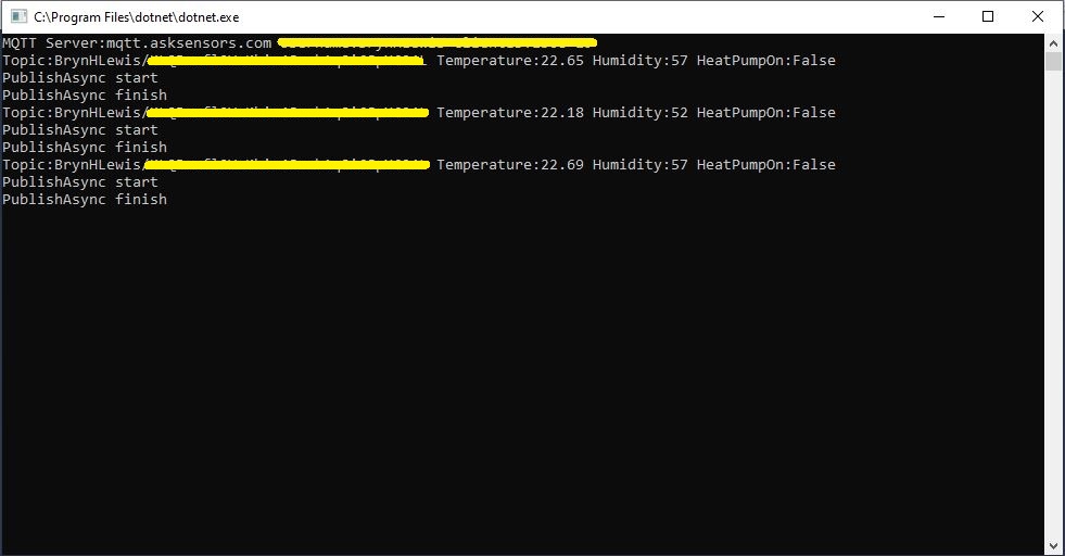
As I’m testing my Message Queue Telemetry Transport(MQTT) LoRa gateway I’m building a proof of concept(PoC) .Net core console application for each IoT platform I would like to support.
This PoC was to confirm that I could connect to the Ask SensorsMQTT API then format topics and payloads correctly.
Console test application
The MQTT broker, username, password, and client ID are command line options.
class Program
{
	private static IMqttClient mqttClient = null;
	private static IMqttClientOptions mqttOptions = null;
	private static string server;
	private static string username;
	private static string apiKey;
	private static string clientID;

	static void Main(string[] args)
	{
		MqttFactory factory = new MqttFactory();
		mqttClient = factory.CreateMqttClient();
		bool heatPumpOn = false;

		if (args.Length != 4)
		{
			Console.WriteLine("[MQTT Server] [UserName] [APIKey] [ClientID]");
			Console.WriteLine("Press <enter> to exit");
			Console.ReadLine();
			return;
		}

		server = args[0];
		username = args[1];
		apiKey = args[2];
		clientID = args[3];

		Console.WriteLine($"MQTT Server:{server} Username:{username} ClientID:{clientID}");

		mqttOptions = new MqttClientOptionsBuilder()
			.WithTcpServer(server)
			.WithCredentials(username, "")
			.WithClientId(clientID)
			//.WithTls() // This is a bit of a worry
			.Build();

		mqttClient.ApplicationMessageReceived += MqttClient_ApplicationMessageReceived;
		mqttClient.Disconnected += MqttClient_Disconnected;
		mqttClient.ConnectAsync(mqttOptions).Wait();

		// AskSensors formatted client state update topic
		string stateTopic = $"{username}/{apiKey}";

		while (true)
		{
			string payloadText;
			double temperature = 22.0 + (DateTime.UtcNow.Millisecond / 1000.0);
			double humidity = 50 + (DateTime.UtcNow.Millisecond / 100.0);
			double speed = 10 + (DateTime.UtcNow.Millisecond / 100.0);
			Console.WriteLine($"Topic:{stateTopic} Temperature:{temperature:0.00} Humidity:{humidity:0} HeatPumpOn:{heatPumpOn}");

			// First JSON attempt didn't work
			payloadText = @"{""Humidity"":55}";

            // Second attempt worked
            payloadText = $"module1=22";

            // Third attempt with "real" values injected
            payloadText = $"module1={temperature}&m2={humidity}";

            var message = new MqttApplicationMessageBuilder()
					.WithTopic(stateTopic)
					.WithPayload(payloadText)
					.WithQualityOfServiceLevel(global::MQTTnet.Protocol.MqttQualityOfServiceLevel.AtLeastOnce)
				   .WithExactlyOnceQoS()
				   //.WithAtLeastOnceQoS()
				   //.WithRetainFlag()
				   .Build();

				Console.WriteLine("PublishAsync start");
				mqttClient.PublishAsync(message).Wait();
				Console.WriteLine("PublishAsync finish");

				Thread.Sleep(30100);
			}
		}

	private static async void MqttClient_Disconnected(object sender, MqttClientDisconnectedEventArgs e)
	{
		Debug.WriteLine("Disconnected");
		await Task.Delay(TimeSpan.FromSeconds(5));

		try
		{
			await mqttClient.ConnectAsync(mqttOptions);
		}
		catch (Exception ex)
		{
			Debug.WriteLine("Reconnect failed {0}", ex.Message);
		}
	}
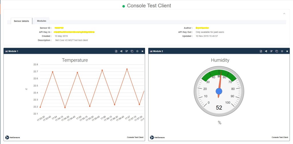
The Ask Sensors screen designer has 8 different types of Graph (line, bar, scatter, gauge, table, binary. digital, map)
Ask sensors dashboard configuration was fairly simple, though sequential numbering of inputs (modules) might require some mapping code.
Overall the initial configuration went smoothly after I figured out the payload format (not JSON), though the functionality (of a free subscription) did appear to be quite limited.
Since I first started building my MQTT gateway there have been several breaking updates to the MQTTNet API which so I will have to refresh all the applications in my solution.
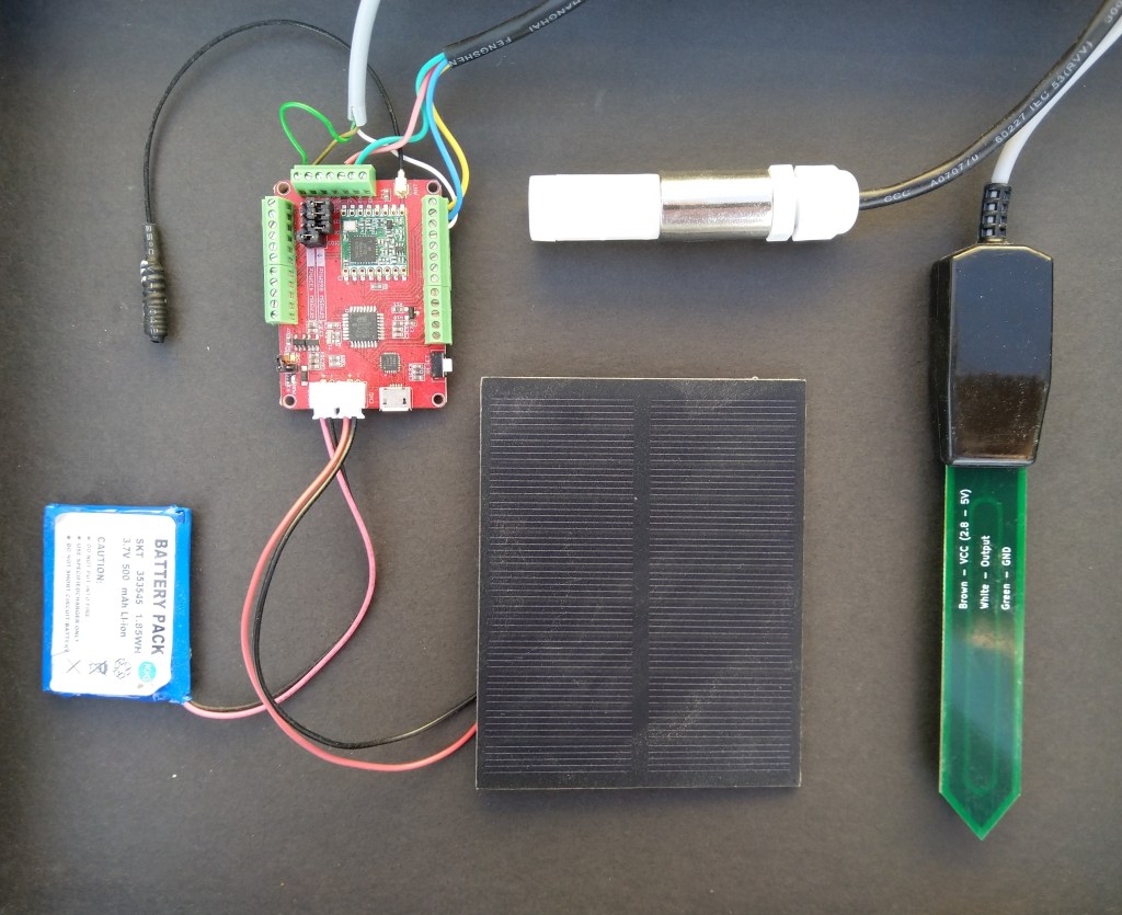
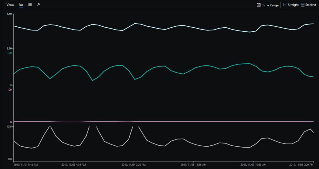
Sample hardwareAzure IoT Central data visualisation
The Maduino device in the picture is a custom version with an onboard Microchip ATSHA204 crypto and authentication chip (currently only use for the unique 72 bit serial number) and a voltage divider connected to the analog pin A6 to monitor the battery voltage.
There are compile time options ATSHA204 & BATTERY_VOLTAGE_MONITOR which can be used to selectively enable this functionality.
I use the Arduino lowpower library to aggressively sleep the device between measurements
// Adjust the delay so period is close to desired sec as possible, first do 8sec chunks.
  int delayCounter = SensorUploadDelay / 8 ;
  for( int i = 0 ; i < delayCounter ; i++ )
  {
     LowPower.powerDown(SLEEP_8S, ADC_OFF, BOD_OFF);
  }

  // Then to 4 sec chunk
  delayCounter =  ( SensorUploadDelay % 8 ) / 4;
  for( int i = 0 ; i < delayCounter ; i++ )
  {
     LowPower.powerDown(SLEEP_4S, ADC_OFF, BOD_OFF);
  }

  // Then to 2 sec chunk
  delayCounter =  ( SensorUploadDelay % 4 ) / 2 ;
  for( int i = 0 ; i < delayCounter ; i++ )
  {
     LowPower.powerDown(SLEEP_2S, ADC_OFF, BOD_OFF);
  }

  // Then to 1 sec chunk
  delayCounter =  ( SensorUploadDelay % 2 ) ;
  for( int i = 0 ; i < delayCounter ; i++ )
  {
     LowPower.powerDown(SLEEP_1S, ADC_OFF, BOD_OFF);
  }
}
I use a spare digital PIN for powering the soil moisture probe so it can be powered down when not in use. I have included a short delay after powering up the device to allow the reading to settle.
  // Turn on soil mosture sensor, take reading then turn off to save power
  digitalWrite(SoilMoistureSensorEnablePin, HIGH);
  delay(SoilMoistureSensorEnableDelay);
  int soilMoistureADCValue = analogRead(SoilMoistureSensorPin);
  digitalWrite(SoilMoistureSensorEnablePin, LOW);
  int soilMoisture = map(soilMoistureADCValue,SoilMoistureSensorMinimum,SoilMoistureSensorMaximum, SoilMoistureValueMinimum, SoilMoistureValueMaximum);
  PayloadAdd( "s", soilMoisture, false);
While trying to debug a deadlock in my RFM69 library I noticed in the logging that I was getting a receive interrupt while putting bytes in the FIFO for transmission.
Register 0x49 - Value 0X00 - Bits 00000000
Register 0x4a - Value 0X00 - Bits 00000000
Register 0x4b - Value 0X00 - Bits 00000000
Register 0x4c - Value 0X00 - Bits 00000000
Register 0x4d - Value 0X00 - Bits 00000000
...
22:58:47.192 Received To 0X22 a 33 byte message hello world RFM69-915-02 10-58-47 CRC Ok True
The thread 0x6a8 has exited with code 0 (0x0).
22:58:48.334 Send-hello world RFM69-915-01 10-58-48
22:58:48.351 Send-Done
22:58:48.388 Received To 0X22 a 33 byte message hello world RFM69-915-02 10-58-52 CRC Ok True
22:58:48.462 Transmit-Done
The thread 0xde4 has exited with code 0 (0x0).
22:58:53.427 Send-hello world RFM69-915-01 10-58-53
22:58:53.445 Send-Done
22:58:53.556 Transmit-Done
22:58:57.382 Received To 0X22 a 33 byte message hello world RFM69-915-02 10-58-57 CRC Ok True
The thread 0x17c has exited with code 0 (0x0).
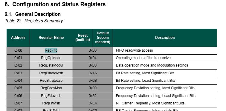
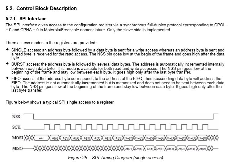
After re-reading the RFM69CW/RFM69HCW module datasheet (based on the Semtech SX1231/SX1231H) I realised my code for loading the FIFO could be more efficient.
SX1231 Register map FIFO
Based on the timing diagram I could remove the loop which loads bytes in the FIFO for transmission.
After stress testing with several client devices this appears to have reduced the scope of a receive interrupt to occur while a packet was being loaded into the FIFO for transmission. I now need to dig deeper into the timing around entering different operational modes and selectively enabling event interrupts.
After problems with interleaved interrupt handling in my Windows 10 IoT Core client I figured the AutoMode used by the plainRFM69 library might be worth investigation. My first Arduino client was based on the plainRFM69 library but had Interoperability issues.
For this attempt I also started with the minimal sample and modified the code to send and receive text messages.
/*
    Copyright (c) 2014, Ivor Wanders, Bryn Lewis 2019
    MIT License, see the LICENSE.md file in the root folder.
*/

#include <SPI.h>
#include <plainRFM69.h>

// slave select pin.
#define SLAVE_SELECT_PIN 10

// connected to the reset pin of the RFM69.
#define RESET_PIN 9

// tie this pin down on the receiver.
#define SENDER_DETECT_PIN A0

const uint8_t tx_buffer[] = "ABCDEFGHIJKLMNOPQRSTURWXYZ1234567890";
//const uint8_t tx_buffer[] = "abcdefghijklmnopqrstuvwxyz1234567890";
uint8_t rx_buffer[sizeof(tx_buffer)] = "";

plainRFM69 rfm = plainRFM69(SLAVE_SELECT_PIN);


void sender() {

  uint32_t start_time = millis();

  uint32_t counter = 1; // the counter which we are going to send.

  while (true) {
    rfm.poll(); // run poll as often as possible.

    if (!rfm.canSend()) {
      continue; // sending is not possible, already sending.
    }

    if ((millis() - start_time) > 1000) { // every 500 ms.
      start_time = millis();

      // be a little bit verbose.
      Serial.print("Send:"); Serial.println(counter);

      // send the number of bytes equal to that set with setPacketLength.
      // read those bytes from memory where counter starts.
      rfm.sendVariable(tx_buffer, counter);

      counter++; // increase the counter.

      if ( counter > strlen(tx_buffer))
      {
        counter = 1;
      }
    }
  }
}

void receiver() {
  uint32_t counter = 0; // to count the messages.

  while (true) {

    rfm.poll(); // poll as often as possible.

    while (rfm.available())
    {
      uint8_t len = rfm.read(rx_buffer); // read the packet into the new_counter.

      // print verbose output.
      Serial.print("Packet Len:");
      Serial.print( len );
      Serial.print(" : ");
      Serial.println((char*)rx_buffer);
    }
  }
}

void setup() {
  Serial.begin(9600);
  SPI.begin();

  bareRFM69::reset(RESET_PIN); // sent the RFM69 a hard-reset.

  //rfm.setRecommended(); // set recommended paramters in RFM69.
  rfm.setPacketType(true, false); // set the used packet type.

  rfm.setBufferSize(2);   // set the internal buffer size.
  rfm.setPacketLength(sizeof(rx_buffer)); // set the packet length.

  rfm.setFrequency((uint32_t)909560000); // set the frequency.

  rfm.setLNA(RFM69_LNA_IMP_200OHM, RFM69_LNA_GAIN_AGC_LOOP);

  // p71, 3 preamble bytes.
  rfm.setPreambleSize(16);

  // p71, 4 bytes sync of 0x01, only start listening when sync is matched.
  //uint8_t syncthing[] = {0xaa, 0x2d, 0xd4};
  uint8_t syncthing[] = {0xd4, 0x2d, 0xaa};
  rfm.setSyncConfig(true, false, sizeof(syncthing), 0);
  rfm.setSyncValue(&syncthing, sizeof(syncthing));

  rfm.dumpRegisters(Serial);

  // baudrate is default, 4800 bps now.

  rfm.receive();
  // set it to receiving mode.

  pinMode(SENDER_DETECT_PIN, INPUT_PULLUP);
  delay(5);
}

void loop() {
  if (digitalRead(SENDER_DETECT_PIN) == LOW) {
    Serial.println("Going Receiver!");
    receiver();
    // this function never returns and contains an infinite loop.
  } else {
    Serial.println("Going sender!");
    sender();
    // idem.
  }
}
I took the list register values and loaded them into a Excel spreadsheet alongside the values from my Windows 10 IoT Core application
First thing I noticed was the order of the three sync byes (Registers 0x2F, 0x30, 0x31) was reversed. I then modified the run method in the Windows 10 code so the registers settings on both devices matched. (I removed the PlainRFM69 SetRecommended call so as many of the default options as possible were used).
I also found an error with the declaration of the RegPacketConfig1DcFree enumeration (Whitening = 0b0100000 vs. Whitening = 0b01000000) which wouldn’t have helped.
Register 0x4c - Value 0X00 - Bits 00000000
Register 0x4d - Value 0X00 - Bits 00000000
...
17:55:53.559 Received 1 byte message A CRC Ok True
.17:55:54.441 Received 2 byte message AB CRC Ok True
.17:55:55.444 Received 3 byte message ABC CRC Ok True
.17:55:56.447 Received 4 byte message ABCD CRC Ok True
.17:55:57.449 Received 5 byte message ABCDE CRC Ok True
.17:55:58.453 Received 6 byte message ABCDEF CRC Ok True
The thread 0x578 has exited with code 0 (0x0).
.17:55:59.622 Received 7 byte message ABCDEFG CRC Ok True
.17:56:00.457 Received 8 byte message ABCDEFGH CRC Ok True
.17:56:01.460 Received 9 byte message ABCDEFGHI CRC Ok True
.17:56:02.463 Received 10 byte message ABCDEFGHIJ CRC Ok True
..17:56:03.955 Received 11 byte message ABCDEFGHIJK CRC Ok True
17:56:04.583 Received 12 byte message ABCDEFGHIJKL CRC Ok True
I did some investigation into that the plainRMF69 code and found the ReadMultiple and WriteMuliple methods reverse the byte order
void bareRFM69::writeMultiple(uint8_t reg, void* data, uint8_t len){
    SPI.beginTransaction(SPISettings(10000000, MSBFIRST, SPI_MODE0));  // gain control of SPI bus
    this->chipSelect(true); // assert chip select
    SPI.transfer(RFM69_WRITE_REG_MASK | (reg & RFM69_READ_REG_MASK));
    uint8_t* r = reinterpret_cast<uint8_t*>(data);
    for (uint8_t i=0; i < len ; i++){
        SPI.transfer(r[len - i - 1]);
    }
    this->chipSelect(false);// deassert chip select
    SPI.endTransaction();    // release the SPI bus
}

void bareRFM69::readMultiple(uint8_t reg, void* data, uint8_t len){
    SPI.beginTransaction(SPISettings(10000000, MSBFIRST, SPI_MODE0));  // gain control of SPI bus
    this->chipSelect(true); // assert chip select

    SPI.transfer((reg % RFM69_READ_REG_MASK));
    uint8_t* r = reinterpret_cast<uint8_t*>(data);
    for (uint8_t i=0; i < len ; i++){
        r[len - i - 1] = SPI.transfer(0);
    }
    this->chipSelect(false);// deassert chip select
    SPI.endTransaction();    // release the SPI bus
}
I won’t be able to use interrupt AutoMode clients with the EasySensors shields as the DIO2 pin is not connected but on the AdaFruit RFM69HCW Radio Bonnet 433MHz or 915MHz it is connected to GPIO24.
While doing yet more stress testing I noticed a couple of odd message go past and a long pause every so often when sending a message in the Visual Studio output window.
I have two Arduino devices sending addressed messages every (both individual and broadcast) to the Adafruit RFM69 HCW Radio Bonnet, on my two Windows 10 IoT Core devices every 100mSec. At the same time the windows 10 devices are sending each other a message every 5 seconds.
To help spot the pauses I added some code to mark any events where there was a significant gap. In this case ” is ASCII character for 0x22 the device address
21:10:30.746 Received To 34 a 23 byte message Hello World ---0x22:236 CRC Ok True
21:10:30.918 Received To 153 a 23 byte message Hello World ---0x99:236 CRC Ok True
21:10:31.399 Received To 34 a 23 byte message Hello World ---0x22:237 CRC Ok True
21:10:31.568 Send-hello world RFM69-915-01 09-10-31
21:10:31.580 Send-Done
21:10:31.592 Received To 34 a 33 byte message """"""""""""""""""""""""""""""""" CRC Ok True
RC-------------------------------------------
21:10:32.052 Received To 34 a 23 byte message Hello World ---0x22:238 CRC Ok True
21:10:32.225 Received To 153 a 23 byte message Hello World ---0x99:238 CRC Ok True
21:10:32.705 Received To 34 a 23 byte message Hello World ---0x22:239 CRC Ok True
There were also still some corrupted messages
21:10:30.746 Received To 34 a 23 byte message Hello World ---0x22:236 CRC Ok True
21:10:30.918 Received To 153 a 23 byte message Hello World ---0x99:236 CRC Ok True
21:10:31.399 Received To 34 a 23 byte message Hello World ---0x22:237 CRC Ok True
21:10:31.568 Send-hello world RFM69-915-01 09-10-31
21:10:31.580 Send-Done
21:10:31.592 Received To 34 a 33 byte message """"""""""""""""""""""""""""""""" CRC Ok True
RC-------------------------------------------
21:10:32.052 Received To 34 a 23 byte message Hello World ---0x22:238 CRC Ok True
21:10:32.225 Received To 153 a 23 byte message Hello World ---0x99:238 CRC Ok True
21:10:32.705 Received To 34 a 23 byte message Hello World ---0x22:239 CRC Ok True
It looks like if the base station receives a message as it is about to send a message the Rfm69Device_OnTransmit never gets called.
It also looks like every so often the transmitter gets stuck on one of Windows 10 devices effectively jamming the frequency.
Transmit stuck on
16:12:10.193 Received To 34 a 22 byte message Hello World ---0x22:65 CRC Ok True
16:12:10.360 Received To 153 a 22 byte message Hello World ---0x99:65 CRC Ok True
16:12:10.831 Received To 34 a 22 byte message Hello World ---0x22:66 CRC Ok True
16:12:10.998 Received To 153 a 22 byte message Hello World ---0x99:66 CRC Ok True
The thread 0x570 has exited with code 0 (0x0).
16:12:11.484 Send-hello world RFM69-915-01 04-12-11
16:12:11.494 Received To 34 a 22 byte message Hello World ---0x22:67 CRC Ok True
16:12:11.504 Send-Done
The thread 0x3a8 has exited with code 0 (0x0).
16:12:16.554 Send-hello world RFM69-915-01 04-12-16
16:12:16.566 Send-Done
16:12:16.660 Transmit-Done
T--------------------------------------------
16:12:16.736 Received To 153 a 22 byte message Hello World ---0x99:75 CRC Ok True
16:12:17.206 Received To 34 a 22 byte message Hello World ---0x22:76 CRC Ok True
16:12:17.374 Received To 153 a 22 byte message Hello World ---0x99:76 CRC Ok True
16:12:18.011 Received To 153 a 22 byte message Hello World ---0x99:77 CRC Ok True


Transmit stuck
16:12:07.591 Transmit-Done
16:12:07.880 Received To 153 a 23 byte message Hello World ---0x99:137 CRC Ok True
16:12:08.533 Received To 153 a 23 byte message Hello World ---0x99:138 CRC Ok True
16:12:08.839 Received To 17 a 24 byte message Hello World ----0x11:139 CRC Ok True
16:12:09.186 Received To 153 a 23 byte message Hello World ---0x99:139 CRC Ok True
16:12:09.493 Received To 17 a 24 byte message Hello World ----0x11:140 CRC Ok True
16:12:10.799 Received To 17 a 24 byte message Hello World ----0x11:142 CRC Ok True
The thread 0xc8 has exited with code 0 (0x0).
16:12:12.567 Send-hello world RFM69-915-02 04-12-12
16:12:12.589 Send-Done
16:12:12.681 Transmit-Done
16:12:16.510 Received To 17 a 33 byte message hello world RFM69-915-01 04-12-16 CRC Ok True
16:12:16.576 Received To 153 a 22 byte message Hello World ---0x99:75 CRC Ok True
16:12:17.025 Received To 153 a 23 byte message Hello World ---0x99:151 CRC Ok True
16:12:17.214 Received To 153 a 22 byte message Hello World ---0x99:76 CRC Ok True
16:12:17.331 Received To 17 a 24 byte message Hello World ----0x11:152 CRC Ok True
The thread 0xfa0 has exited with code 0 (0x0).
16:12:17.661 Send-hello world RFM69-915-02 04-12-17
16:12:17.680 Send-Done
16:12:17.772 Transmit-Done
16:12:17.851 Received To 153 a 22 byte message Hello World ---0x99:77 CRC Ok True
16:12:18.331 Received To 153 a 23 byte message Hello World ---0x99:153 CRC Ok True
16:12:18.489 Received To 153 a 22 byte message Hello World ---0x99:78 CRC Ok True
16:12:18.638 Received To 17 a 24 byte message Hello World ----0x11:154 CRC Ok True
16:12:18.985 Received To 153 a 23 byte message Hello World ---0x99:154 CRC Ok True
16:12:19.291 Received To 17 a 24 byte message Hello World ----0x11:155 CRC Ok True
16:12:19.638 Received To 153 a 23 byte message Hello World ---0x99:155 CRC Ok True
16:12:19.944 Received To 17 a 24 byte message Hello World ----0x11:156 CRC Ok True
16:12:20.291 Received To 153 a 23 byte message Hello World ---0x99:156 CRC Ok True
16:12:20.597 Received To 17 a 24 byte message Hello World ----0x11:157 CRC Ok True
Then as rfm69Device.SetMode(Rfm69HcwDevice.RegOpModeMode.Receive) hasn’t been called no messages are received until another message is sent.
It looks like a timing issue around access to the message fifo (I have that in a critical section) so I need todo some more debugging. Maybe purging the receive buffer
Again, while doing some stress testing I noticed an odd message go past in the Visual Studio output window. I had multiple devices sending addressed messages (both individual and broadcast) to the Adafruit RFM69 HCW Radio Bonnet, on my Windows 10 IoT Core device while it was sending a message every 5 seconds.
Received From 102 a 15 byte message Hello World:161
23:42:33.343 RegIrqFlags2 01100110
23:42:33.356 RegIrqFlags1 11011001
23:42:33.374 Address 0X99 10011001
Received From 153 a 15 byte message Hello World:106
23:42:33.761 RegIrqFlags2 01100110
23:42:33.774 RegIrqFlags1 11011001
23:42:33.791 Address 0X66 01100110
Received From 102 a 15 byte message Hello World:162
The thread 0xd20 has exited with code 0 (0x0).
23:42:34.500 RegIrqFlags2 01100110
23:42:34.501 Send-hello world 11:42:34 PM
23:42:34.520 RegIrqFlags1 11011001
23:42:34.545 Send-Done
23:42:34.551 Address 0X10 00010000
Received From 16 a 15 byte message h    WWWWWWWWoo
23:42:34.686 RegIrqFlags2 00001000
23:42:34.701 RegIrqFlags1 10110000
23:42:34.715 Transmit-Done
Transmit-Done
23:42:34.902 RegIrqFlags2 01100110
23:42:34.915 RegIrqFlags1 11011001
23:42:34.931 Address 0X66 01100110
Received From 102 a 15 byte message Hello World:163
23:42:35.626 RegIrqFlags2 01100110
23:42:35.640 RegIrqFlags1 11011001
23:42:35.659 Address 0X99 10011001
Received From 153 a 15 byte message Hello World:108
23:42:36.042 RegIrqFlags2 01100110
23:42:36.055 RegIrqFlags1 11011001
23:42:36.073 Address 0X66 01100110
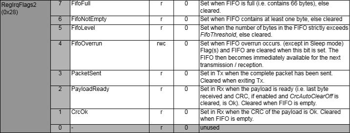
The RegIrqFlags2 CrcOk (bit 1) was set and the message was corrupt.
RegIrqFlags2 bit flags from SX1231 datasheet
I have added code to check the CRC on inbound messages if this functionality is enabled. So the library can be used with CRCs disabled I have added a flag to the OnDataReceivedEventArgs class to indicate whether the CRC on the inbound message was OK.
private readonly Object Rfm9XRegFifoLock = new object();
...
private void ProcessPayloadReady(RegIrqFlags1 irqFlags1, RegIrqFlags2 irqFlags2)
{
	byte? address = null;
	byte numberOfBytes;
	byte[] messageBytes;

	lock (Rfm9XRegFifoLock)
	{
		// Read the length of the buffer if variable length packets
		if (PacketFormat == RegPacketConfig1PacketFormat.VariableLength)
		{
			numberOfBytes = RegisterManager.ReadByte((byte)Rfm69HcwDevice.Registers.RegFifo);
		}
		else
		{
			numberOfBytes = PayloadLength;
		}

		// Remove the address from start of the payload
		if (AddressingEnabled)
		{
			address = RegisterManager.ReadByte((byte)Rfm69HcwDevice.Registers.RegFifo);

			Debug.WriteLine("{0:HH:mm:ss.fff} Address 0X{1:X2} {2}", DateTime.Now, address, Convert.ToString((byte)address, 2).PadLeft(8, '0'));
			numberOfBytes--;
		}

		// Allocate a buffer for the payload and read characters from the Fifo
		messageBytes = new byte[numberOfBytes];

		for (int i = 0; i < numberOfBytes; i++)
		{
			messageBytes[i] = RegisterManager.ReadByte((byte)Rfm69HcwDevice.Registers.RegFifo);
		}
	}
...
public void SendMessage(byte[] messageBytes)
{
#region Guard conditions
#endregion

	lock (Rfm9XRegFifoLock)
	{
		SetMode(RegOpModeMode.StandBy);

		if (PacketFormat == RegPacketConfig1PacketFormat.VariableLength)
		{
			RegisterManager.WriteByte((byte)Registers.RegFifo, (byte)messageBytes.Length);
		}

		foreach (byte b in messageBytes)
		{
			this.RegisterManager.WriteByte((byte)Registers.RegFifo, b);
		}

		SetMode(RegOpModeMode.Transmit);
	}
}
I can most probably reduce the duration which I hold the lock for but that will require some more stress testing.
While doing some stress testing I noticed an odd message go past in the Visual Studio output window. I had multiple devices sending addressed messages (both individual and broadcast) to the Adafruit RFM69 HCW Radio Bonnet, on my Windows 10 IoT Core device while it was sending a message every 5 seconds.
Received From 153 a 13 byte message Hello World:7
18:43:56.544 RegIrqFlags2 01100110
18:43:56.558 RegIrqFlags1 11011001
18:43:56.575 Address 0X66 01100110
Received From 102 a 15 byte message Hello World:162
The thread 0x254 has exited with code 0 (0x0).
18:43:57.699 Send-hello world 6:43:57 PM
18:43:57.699 RegIrqFlags2 01100110
18:43:57.731 RegIrqFlags1 10000000
18:43:57.747 Address 0X66 01100110
18:43:57.765 Send-Done
Received From 102 a 15 byte message Hello Woooooooo
18:43:57.987 RegIrqFlags2 00001000
18:43:58.003 RegIrqFlags1 10110000
18:43:58.017 Transmit-Done
Transmit-Done
18:43:58.825 RegIrqFlags2 01100110
18:43:58.838 RegIrqFlags1 11011001
18:43:58.857 Address 0X66 01100110
Received From 102 a 15 byte message Hello World:164
18:43:59.966 RegIrqFlags2 01100110
18:43:59.979 RegIrqFlags1 11011001
18:43:59.998 Address 0X66 01100110
The odd thing was that the RegIrqFlags2 CrcOk (bit 1) was set but the message was still corrupt.
RegIrqFlags2 bit flags from SX1231 datasheet
After looking at the code I think the problem was the reading of the received message bytes from the device FIFO and the writing of bytes of message to be transmitted into the device FIFO overlapped. To stop this occurring again I have added code to synchronise access (using a Lock) to the FIFO.
private readonly Object Rfm9XRegFifoLock = new object();
...
private void ProcessPayloadReady(RegIrqFlags1 irqFlags1, RegIrqFlags2 irqFlags2)
{
	byte? address = null;
	byte numberOfBytes;
	byte[] messageBytes;

	lock (Rfm9XRegFifoLock)
	{
		// Read the length of the buffer if variable length packets
		if (PacketFormat == RegPacketConfig1PacketFormat.VariableLength)
		{
			numberOfBytes = RegisterManager.ReadByte((byte)Rfm69HcwDevice.Registers.RegFifo);
		}
		else
		{
			numberOfBytes = PayloadLength;
		}

		// Remove the address from start of the payload
		if (AddressingEnabled)
		{
			address = RegisterManager.ReadByte((byte)Rfm69HcwDevice.Registers.RegFifo);

			Debug.WriteLine("{0:HH:mm:ss.fff} Address 0X{1:X2} {2}", DateTime.Now, address, Convert.ToString((byte)address, 2).PadLeft(8, '0'));
			numberOfBytes--;
		}

		// Allocate a buffer for the payload and read characters from the Fifo
		messageBytes = new byte[numberOfBytes];

		for (int i = 0; i < numberOfBytes; i++)
		{
			messageBytes[i] = RegisterManager.ReadByte((byte)Rfm69HcwDevice.Registers.RegFifo);
		}
	}
...
public void SendMessage(byte[] messageBytes)
{
#region Guard conditions
#endregion

	lock (Rfm9XRegFifoLock)
	{
		SetMode(RegOpModeMode.StandBy);

		if (PacketFormat == RegPacketConfig1PacketFormat.VariableLength)
		{
			RegisterManager.WriteByte((byte)Registers.RegFifo, (byte)messageBytes.Length);
		}

		foreach (byte b in messageBytes)
		{
			this.RegisterManager.WriteByte((byte)Registers.RegFifo, b);
		}

		SetMode(RegOpModeMode.Transmit);
	}
}
The code has been running for a day without any corrupted messages so the lock appears to be working. I can most probably reduce the duration which I hold the lock for but that will require some more stress testing.
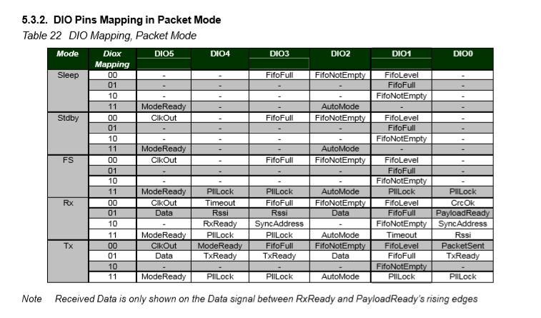
The RFM69CW/RFM69HCW module (based on the Semtech SX1231/SX1231H) has configurable digital outputs (RegDIOMapping1 & RegDIOMapping2) . Which I use to trigger interrupts on my Windows 10 IoT Core or Arduino devices. Currently (Sep 2019) the library only supports the mapping of the digital outputs D0 & D1 when the RFM69 is in Packet Mode.
RegiDIOMapping0 & RegDIOMapping2 settings for DIO thru DIO5
I added some additional constants and enumerations for the other settings configured in RegDioMapping1 & RegDioMapping2.
I had several failed attempts at defining suitable enumerations for configuring the RegDioMapping1 & RegDioMapping2 registers. I initially started with an enumeration for each Mode (Sleep, StandBy etc.) but the implementation was quite complex. The initial version only supports DIO0 & DIO1 as most of the shields I have, only DIO0 adn/or DIO1 are connected.
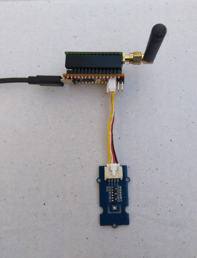
Seeeduino Nano easySensors shield and Grove VOC & eCO2 Sensor
Seeeduino Nano devices have a single on-board I2C socket which meant I didn’t need a Grove Shield for Arduino Nano which reduced the size and cost of the sensor node.
My first attempt failed with an issues accessing an Analog port to read the serial number from the Microchip ATSHA204 security chip. After looking at the Seeed SGP30 library source code (based on Sensiron samples) I think the my Nano device was running out of memory. I then searched for other Arduino compatible SGP30 libraries and rebuilt he application with the one from Sparkfun,
/*
  Copyright ® 2019 August devMobile Software, All Rights Reserved

  THIS CODE AND INFORMATION IS PROVIDED "AS IS" WITHOUT WARRANTY OF ANY
  KIND, EITHER EXPRESSED OR IMPLIED, INCLUDING BUT NOT LIMITED TO THE
  IMPLIED WARRANTIES OF MERCHANTABILITY AND/OR FITNESS FOR A PARTICULAR
  PURPOSE.

  You can do what you want with this code, acknowledgment would be nice.
  http://www.devmobile.co.nz

  Seeedstudio Grove - VOC and eCO2 Gas Sensor (SGP30)
  https://www.seeedstudio.com/Grove-VOC-and-eCO2-Gas-Sensor-SGP30-p-3071.html

  Seeeduino Nano
  https://www.seeedstudio.com/Seeeduino-Nano-p-4111.html

  Polycarbonate enclosure approx 3.5" x 4.5"
    2 x Cable glands
    1 x Grommet to seal SMA antenna connector
    3M command adhesive strips to hold battery & device in place

*/
#include <stdlib.h>
#include "SparkFun_SGP30_Arduino_Library.h"
#include <LoRa.h>
#include <sha204_library.h>

//#define DEBUG
//#define DEBUG_TELEMETRY
//#define DEBUG_LORA
#define DEBUG_VOC_AND_CO2

#define UNITS_VOC "ppb"
#define UNITS_CO2 "ppm"

// LoRa field gateway configuration (these settings must match your field gateway)
const byte DeviceAddressMaximumLength = 15 ;
const char FieldGatewayAddress[] = {"LoRaIoT1"};
const float FieldGatewayFrequency =  915000000.0;
const byte FieldGatewaySyncWord = 0x12 ;

// Payload configuration
const int ChipSelectPin = 10;
const int ResetPin = 9;
const int InterruptPin = 2;

// LoRa radio payload configuration
const byte SensorIdValueSeperator = ' ' ;
const byte SensorReadingSeperator = ',' ;
const unsigned long SensorUploadDelay = 60000;

// ATSHA204 secure authentication, validation with crypto and hashing (currently only using for unique serial number)
const byte Atsha204Port = A3;
atsha204Class sha204(Atsha204Port);
const byte DeviceSerialNumberLength = 9 ;
byte deviceSerialNumber[DeviceSerialNumberLength] = {""};

SGP30 mySensor; //create an object of the SGP30 class

const byte PayloadSizeMaximum = 64 ;
byte payload[PayloadSizeMaximum];
byte payloadLength = 0 ;


void setup()
{
  Serial.begin(9600);

#ifdef DEBUG
  while (!Serial);
#endif

  Serial.println("Setup called");

  Serial.print("Field gateway:");
  Serial.print(FieldGatewayAddress ) ;
  Serial.print(" Frequency:");
  Serial.print( FieldGatewayFrequency,0 ) ;
  Serial.print("MHz SyncWord:");
  Serial.print( FieldGatewaySyncWord ) ;
  Serial.println();

   // Retrieve the serial number then display it nicely
  if(sha204.getSerialNumber(deviceSerialNumber))
  {
    Serial.println("sha204.getSerialNumber failed");
    while (true); // Drop into endless loop requiring restart
  }

  Serial.print("SNo:");
  DisplayHex( deviceSerialNumber, DeviceSerialNumberLength);
  Serial.println();

  Serial.println("LoRa setup start");

  // override the default chip select and reset pins
  LoRa.setPins(ChipSelectPin, ResetPin, InterruptPin);
  if (!LoRa.begin(FieldGatewayFrequency))
  {
    Serial.println("LoRa begin failed");
    while (true); // Drop into endless loop requiring restart
  }

  // Need to do this so field gateway pays attention to messsages from this device
  LoRa.enableCrc();
  LoRa.setSyncWord(FieldGatewaySyncWord);

#ifdef DEBUG_LORA
  LoRa.dumpRegisters(Serial);
#endif
  Serial.println("LoRa Setup done.");

  // Configure the DF Robot SHT20, temperature & humidity sensor
  Serial.println("SGP30 setup start");
  Wire.begin();
  if(mySensor.begin() == false)
  {
    Serial.println("SQP-30 initialisation failed");
    while (true); // Drop into endless loop requiring restart
  }
  mySensor.initAirQuality();
  delay(1000);
  Serial.println("SGP30 setup done");

  PayloadHeader((byte *)FieldGatewayAddress,strlen(FieldGatewayAddress), deviceSerialNumber, DeviceSerialNumberLength);

  Serial.println("Setup done");
  Serial.println();
}


void loop()
{
  unsigned long currentMilliseconds = millis();

  Serial.println("Loop called");

  mySensor.measureAirQuality();

  PayloadReset();

  PayloadAdd( "v", mySensor.TVOC, false);

  PayloadAdd( "c", mySensor.CO2, false);

  #ifdef DEBUG_VOC_AND_CO2
    Serial.print("VoC:");
    Serial.print( mySensor.TVOC ) ;
    Serial.print( UNITS_VOC ) ;
    Serial.print(" Co2:");
    Serial.print( mySensor.CO2 ) ;
    Serial.println( UNITS_CO2 ) ;
  #endif

  #ifdef DEBUG_TELEMETRY
    Serial.println();
    Serial.print("RFM9X/SX127X Payload length:");
    Serial.print(payloadLength);
    Serial.println(" bytes");
  #endif

  LoRa.beginPacket();
  LoRa.write(payload, payloadLength);
  LoRa.endPacket();

  Serial.println("Loop done");
  Serial.println();

  delay(SensorUploadDelay - (millis() - currentMilliseconds ));
}


void PayloadHeader( const byte *to, byte toAddressLength, const byte *from, byte fromAddressLength)
{
  byte addressesLength = toAddressLength + fromAddressLength ;

  payloadLength = 0 ;

  // prepare the payload header with "To" Address length (top nibble) and "From" address length (bottom nibble)

  payload[payloadLength] = (toAddressLength << 4) | fromAddressLength ;
  payloadLength += 1;

  // Copy the "To" address into payload
  memcpy(&payload[payloadLength], to, toAddressLength);
  payloadLength += toAddressLength ;

  // Copy the "From" into payload
  memcpy(&payload[payloadLength], from, fromAddressLength);
  payloadLength += fromAddressLength ;
}


void PayloadAdd( const char *sensorId, float value, byte decimalPlaces, bool last)
{
  byte sensorIdLength = strlen( sensorId ) ;

  memcpy( &payload[payloadLength], sensorId,  sensorIdLength) ;
  payloadLength += sensorIdLength ;
  payload[ payloadLength] = SensorIdValueSeperator;
  payloadLength += 1 ;
  payloadLength += strlen( dtostrf(value, -1, decimalPlaces, (char *)&payload[payloadLength]));
  if (!last)
  {
    payload[ payloadLength] = SensorReadingSeperator;
    payloadLength += 1 ;
  }

#ifdef DEBUG_TELEMETRY
  Serial.print("PayloadAdd float-payloadLength:");
  Serial.print( payloadLength);
  Serial.println( );
#endif
}


void PayloadAdd( char *sensorId, int value, bool last )
{
  byte sensorIdLength = strlen(sensorId) ;

  memcpy(&payload[payloadLength], sensorId,  sensorIdLength) ;
  payloadLength += sensorIdLength ;
  payload[ payloadLength] = SensorIdValueSeperator;
  payloadLength += 1 ;
  payloadLength += strlen(itoa( value,(char *)&payload[payloadLength],10));
  if (!last)
  {
    payload[ payloadLength] = SensorReadingSeperator;
    payloadLength += 1 ;
  }

#ifdef DEBUG_TELEMETRY
  Serial.print("PayloadAdd int-payloadLength:" );
  Serial.print(payloadLength);
  Serial.println( );
#endif
}


void PayloadAdd( char *sensorId, unsigned int value, bool last )
{
  byte sensorIdLength = strlen(sensorId) ;

  memcpy(&payload[payloadLength], sensorId,  sensorIdLength) ;
  payloadLength += sensorIdLength ;
  payload[ payloadLength] = SensorIdValueSeperator;
  payloadLength += 1 ;
  payloadLength += strlen(utoa( value,(char *)&payload[payloadLength],10));
  if (!last)
  {
    payload[ payloadLength] = SensorReadingSeperator;
    payloadLength += 1 ;
  }

#ifdef DEBUG_TELEMETRY
  Serial.print("PayloadAdd uint-payloadLength:");
  Serial.print(payloadLength);
  Serial.println( );
#endif
}


void PayloadReset()
{
  byte fromAddressLength = payload[0] & 0xf ;
  byte toAddressLength = payload[0] >> 4 ;

  payloadLength = toAddressLength + fromAddressLength + 1;
}


void DisplayHex( byte *byteArray, byte length)
{
  for (int i = 0; i < length ; i++)
  {
    // Add a leading zero
    if ( byteArray[i] < 16)
    {
      Serial.print("0");
    }
    Serial.print(byteArray[i], HEX);
    if ( i < (length-1)) // Don't put a - after last digit
    {
      Serial.print("-");
    }
  }
}
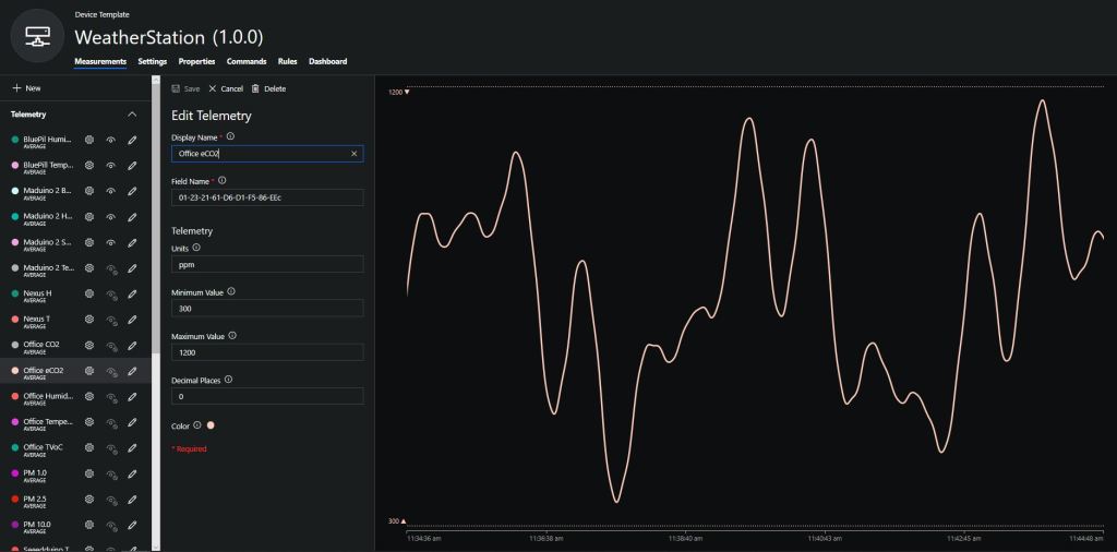
To configure the device in Azure IoT Central (similar process for Adafruit.IO, working on support for losant, and ubidots) I copied the SNo: from the Arduino development tool logging window and appended c for the CO2 parts per million (ppm), v for VOC parts per billion (ppb) unique serial number from the ATSHA204A chip. (N.B. pay attention to the case of the field names they are case sensitive)
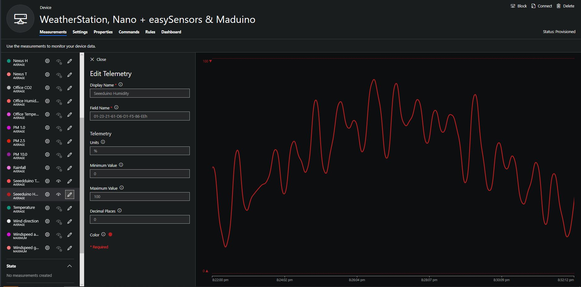
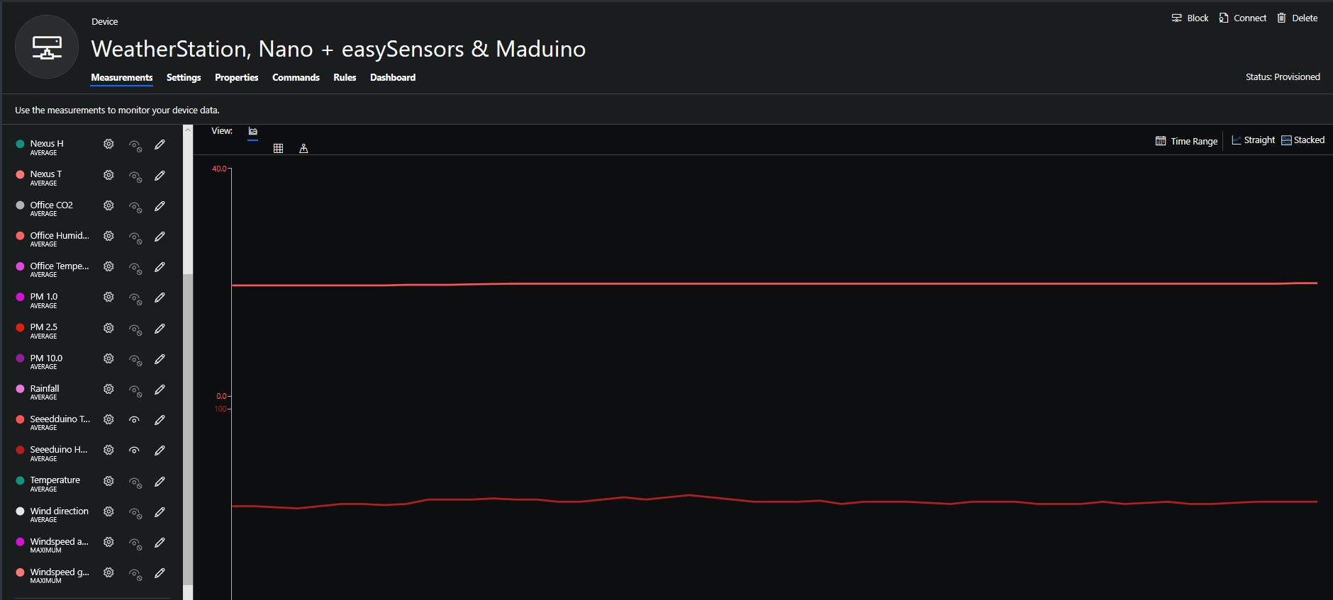
Azure IoT Central configuration
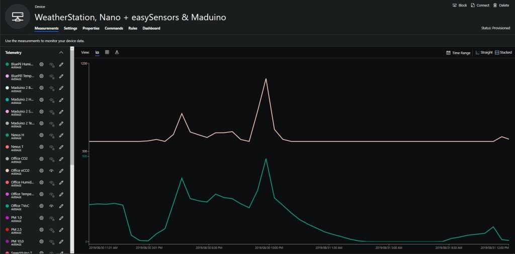
Overall the performance of the VoC sensor data is looking pretty positive, the eCO2 readings need some further investigation as they track the VOC levels. The large spike in the graph below is me putting an open vivid marker on my desk near the sensor.
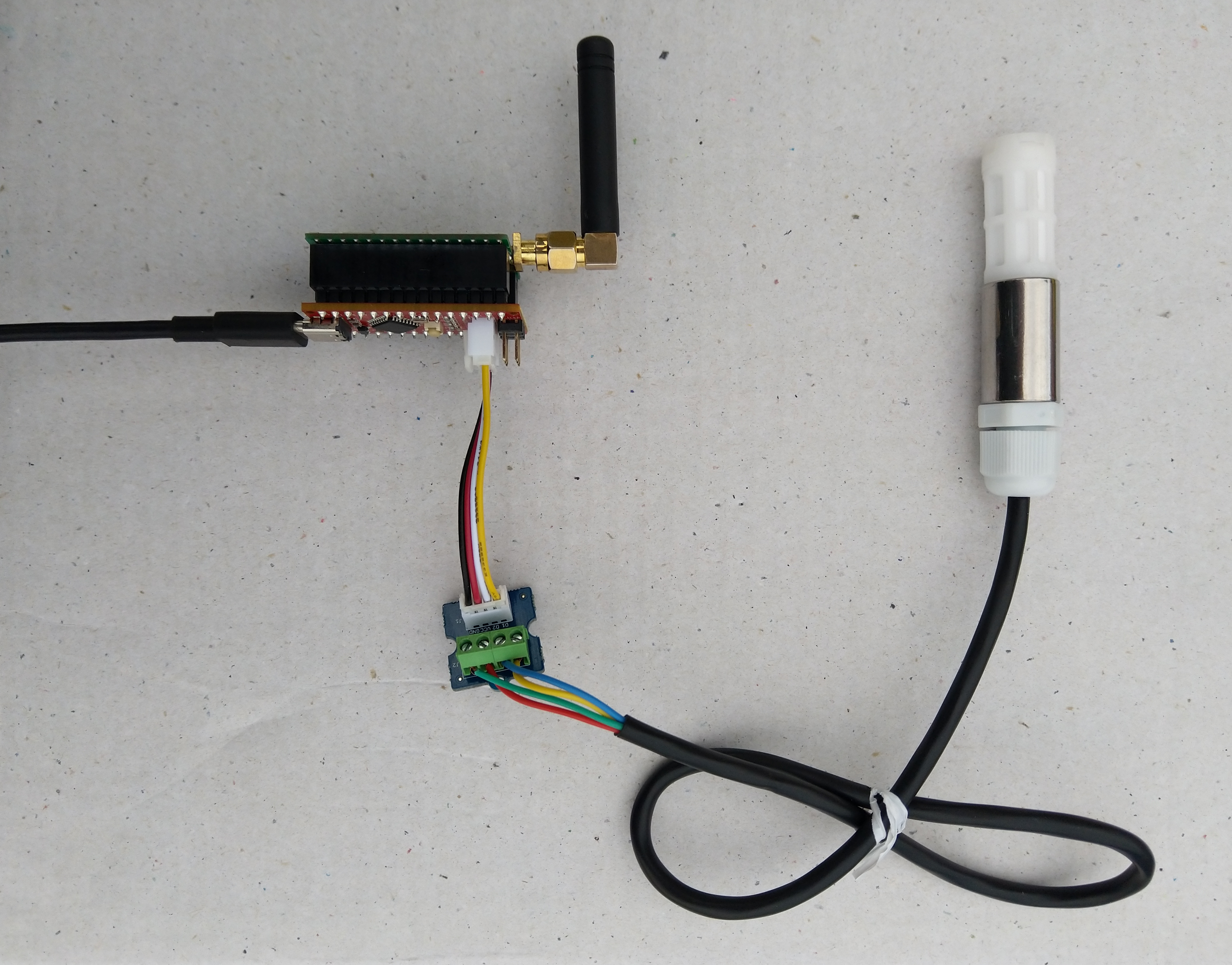
Seeeduino Nano, EasySensors Shield & DF Robot Sensor test rig
The Seeeduino Nano devices I’m testing have a single on-board I2C socket which meant I didn’t need a Grove Shield for Arduino Nano which reduced the size and cost of the sensor node.
To configure the device in Azure IoT Central (similar process for Adafruit.IO, working on support for losant,and ubidots I copied the SNo: from the Arduino development tool logging window and appended p10 for PM 1 value, p25 for PM2.5 value and p100 for PM10 value to the unique serial number from the ATSHA204A chip. (N.B. pay attention to the case of the field names they are case sensitive)
When I moved the sensor indoors it appeared to take a while to warm up and after a while the metal body still felt cold. The sensor element is surrounded by quite a bit of protective packaging for outdoors use and I that would have a bit more thermal inertia the than the lightweight indoor enclosure.
It would be good to run the sensor alongside a calibrated temperature & humidity sensor to see how accurate and responsive it is.