Random wanderings through Microsoft Azure esp. PaaS plumbing, the IoT bits, AI on Micro controllers, AI on Edge Devices, .NET nanoFramework, .NET Core on *nix and ML.NET+ONNX
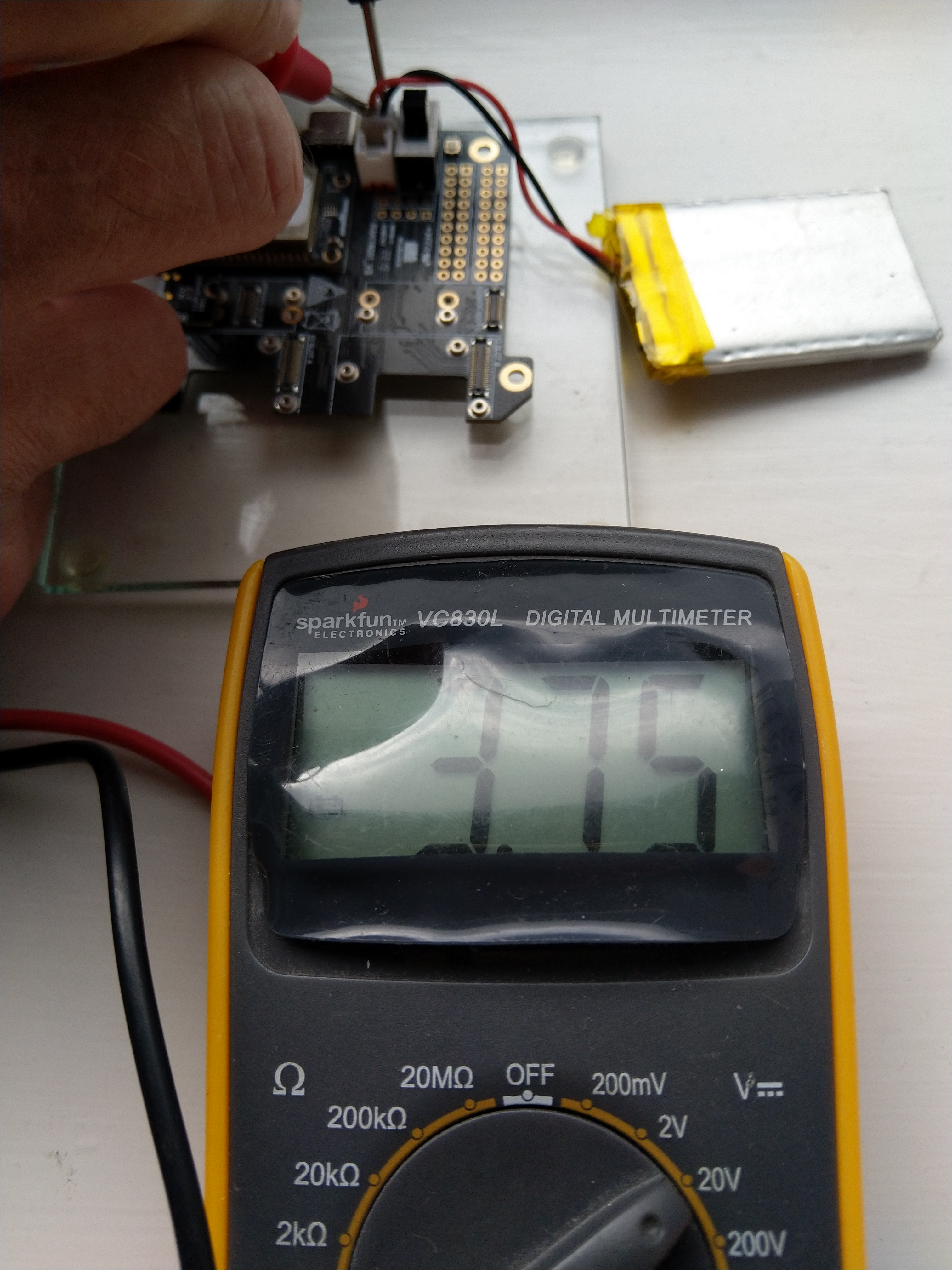
The voltage my test setup was calculating looked wrong, then I realised that the sample calculation in the RAK Wireless forums wasn’t applicable to my setup.
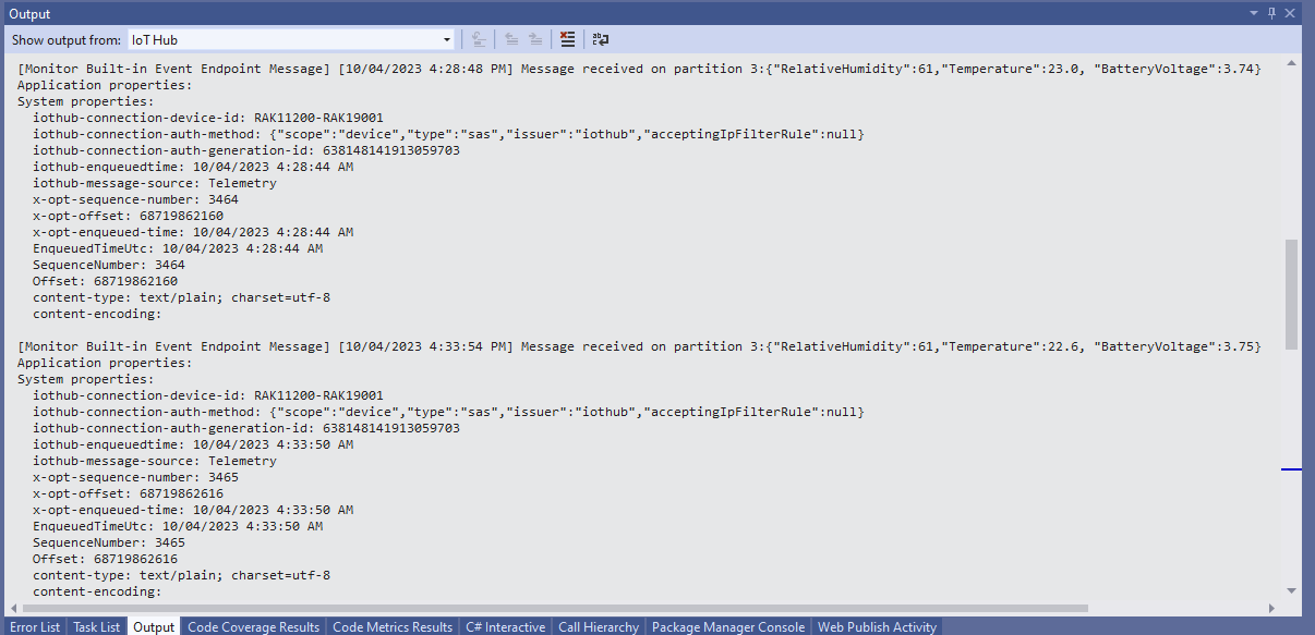
I updated the formula used to calculate the battery voltage and deployed the application
public static void Main()
{
Debug.WriteLine($"{DateTime.UtcNow:HH:mm:ss} devMobile.IoT.RAK.Wisblock.AzureIoTHub.RAK11200.PowerSleep starting");
Thread.Sleep(5000);
try
{
double batteryVoltage;
Configuration.SetPinFunction(Gpio.IO04, DeviceFunction.I2C1_DATA);
Configuration.SetPinFunction(Gpio.IO05, DeviceFunction.I2C1_CLOCK);
Debug.WriteLine($"{DateTime.UtcNow:HH:mm:ss} Battery voltage measurement");
// Configure Analog input (AIN0) port then read the "battery charge"
AdcController adcController = new AdcController();
using (AdcChannel batteryVoltageAdcChannel = adcController.OpenChannel(AdcControllerChannel))
{
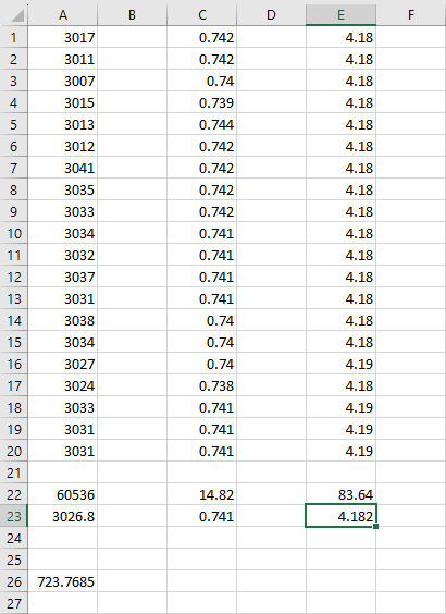
batteryVoltage = batteryVoltageAdcChannel.ReadValue() / 723.7685;
Debug.WriteLine($" BatteryVoltage {batteryVoltage:F2}");
if (batteryVoltage < Config.BatteryVoltageBrownOutThreshold)
{
Sleep.EnableWakeupByTimer(Config.FailureRetryInterval);
Sleep.StartDeepSleep();
}
}
catch (Exception ex)
{
...
}
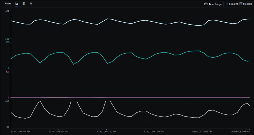
To test the accuracy of the voltage calculation I am going to run my setup on the office windowsill for a week regularly measuring the voltage. Then, turn the solar panel over (so the battery is not getting charged) and monitor the battery discharging until the RAK11200 WisBlock WiFi Module won’t connect to the network.
After some “tinkering” I found the voltage calculation was surprisingly accurate (usually within 0.01V) for my RAK19001 and RAK19007 base boards.
When the battery voltage was close to its minimum working voltage of the ESP32 device it would reboot when the WifiNetworkHelper.ConnectDhcp method was called. This would quickly drain the battery flat even when the solar panel was trying to charge the battery.
Now, before trying to connect to the wireless network the battery voltage is checked and if too low (more experimentation required) the device goes into a deep sleep for a configurable period (more experimentation required). This is so the solar panel can charge the battery to a level where wireless connectivity will work.
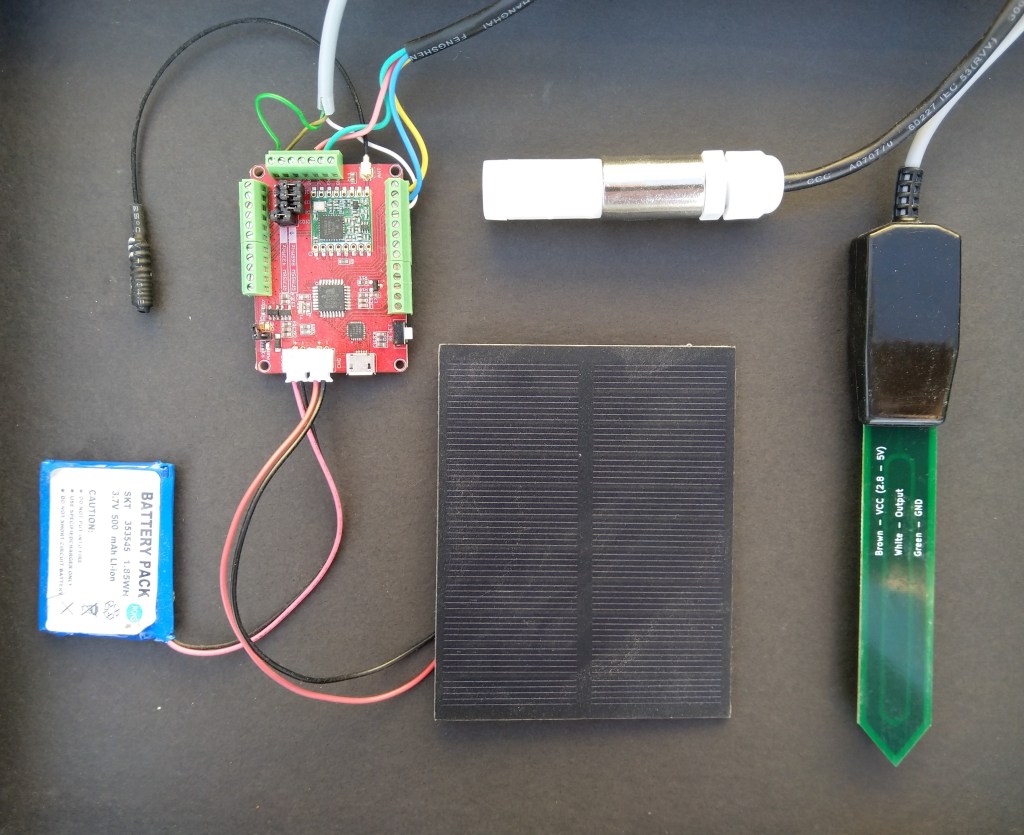
Sample hardwareAzure IoT Central data visualisation
The Maduino device in the picture is a custom version with an onboard Microchip ATSHA204 crypto and authentication chip (currently only use for the unique 72 bit serial number) and a voltage divider connected to the analog pin A6 to monitor the battery voltage.
There are compile time options ATSHA204 & BATTERY_VOLTAGE_MONITOR which can be used to selectively enable this functionality.
I use the Arduino lowpower library to aggressively sleep the device between measurements
// Adjust the delay so period is close to desired sec as possible, first do 8sec chunks.
  int delayCounter = SensorUploadDelay / 8 ;
  for( int i = 0 ; i < delayCounter ; i++ )
  {
     LowPower.powerDown(SLEEP_8S, ADC_OFF, BOD_OFF);
  }

  // Then to 4 sec chunk
  delayCounter =  ( SensorUploadDelay % 8 ) / 4;
  for( int i = 0 ; i < delayCounter ; i++ )
  {
     LowPower.powerDown(SLEEP_4S, ADC_OFF, BOD_OFF);
  }

  // Then to 2 sec chunk
  delayCounter =  ( SensorUploadDelay % 4 ) / 2 ;
  for( int i = 0 ; i < delayCounter ; i++ )
  {
     LowPower.powerDown(SLEEP_2S, ADC_OFF, BOD_OFF);
  }

  // Then to 1 sec chunk
  delayCounter =  ( SensorUploadDelay % 2 ) ;
  for( int i = 0 ; i < delayCounter ; i++ )
  {
     LowPower.powerDown(SLEEP_1S, ADC_OFF, BOD_OFF);
  }
}
I use a spare digital PIN for powering the soil moisture probe so it can be powered down when not in use. I have included a short delay after powering up the device to allow the reading to settle.
  // Turn on soil mosture sensor, take reading then turn off to save power
  digitalWrite(SoilMoistureSensorEnablePin, HIGH);
  delay(SoilMoistureSensorEnableDelay);
  int soilMoistureADCValue = analogRead(SoilMoistureSensorPin);
  digitalWrite(SoilMoistureSensorEnablePin, LOW);
  int soilMoisture = map(soilMoistureADCValue,SoilMoistureSensorMinimum,SoilMoistureSensorMaximum, SoilMoistureValueMinimum, SoilMoistureValueMaximum);
  PayloadAdd( "s", soilMoisture, false);
There is also a 433MHz version available at the same price
The code is pretty basic, it shows how to pack the payload and set the necessary RFM9X/SX127XLoRa module configuration, has no power conservation, advanced wireless configuration etc.
The onboard sockets for battery and charging make the device easier to package and power in the field.
The Grove 4 pin Female Jumper to Grove 4 pin Conversion Cable was a quick & convenient way to get the I2C Grove temperature and humidity sensor connected up.