Random wanderings through Microsoft Azure esp. PaaS plumbing, the IoT bits, AI on Micro controllers, AI on Edge Devices, .NET nanoFramework, .NET Core on *nix and ML.NET+ONNX
I had been planning this for a while, then the code broke when I tried to build a version for my SparkFun LoRa Gateway-1-Channel (ESP32). There was a namespace (static configuration class in configuration.cs) collision and the length of SX127XDevice.cs file was getting silly.
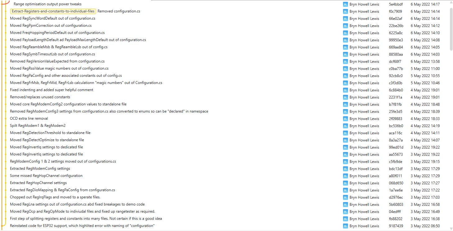
This refactor took a couple of days and really changed the structure of the library.
VS2022 Solution structure after refactoring
I went through the SX127XDevice.cs extracting the enumerations, masks and defaults associated with the registers the library supports.
The library is designed to be a approximate .NET nanoFramework equivalent of Arduino-LoRa so it doesn’t support/implement all of the functionality of the SemtechSX127X. Still got a bit of refactoring to go but the structure is slowly improving.
I use Fork to manage my Github repositories, it’s an excellent product especially as it does a pretty good job of keeping me from screwing up.
All the previous versions of my.NET nanoFrameworkSemtech SX127X (LoRa® Mode) library only supported a Dio0 (RegDioMapping1 bits 6&7) EventHandler. This version supports mapping Dio0, Dio1, Dio2, Dio3, Dio4 and Dio5.
The SX127XLoRaDeviceClient main now has OnRxTimeout, OnReceive, OnPayloadCrcError, OnValidHeader, OnTransmit, OnChannelActivityDetectionDone, OnFhssChangeChannel, and OnChannelActivityDetected event handlers (Based on RegIrqFlags bit ordering)
The Dio0 pin number is the only required pin number parameter, the resetPin, and Dio1 thru Dio5 pin numbers are optional. All the RegDioMapping1 and RegDioMapping2 mappings are disabled on intialisation so there should be no events while the SX127X is being configured.
public SX127XDevice(SpiDevice spiDevice, GpioController gpioController,
int dio0Pin,
int resetPin = 0, // Odd order so as not to break exisiting code
int dio1Pin = 0,
int dio2Pin = 0,
int dio3Pin = 0,
int dio4Pin = 0,
int dio5Pin = 0
)
{
_gpioController = gpioController;
// Factory reset pin configuration
if (resetPin != 0)
{
_resetPin = resetPin;
_gpioController.OpenPin(resetPin, PinMode.Output);
_gpioController.Write(resetPin, PinValue.Low);
Thread.Sleep(20);
_gpioController.Write(resetPin, PinValue.High);
Thread.Sleep(50);
}
_registerManager = new RegisterManager(spiDevice, RegisterAddressReadMask, RegisterAddressWriteMask);
// Once the pins setup check that SX127X chip is present
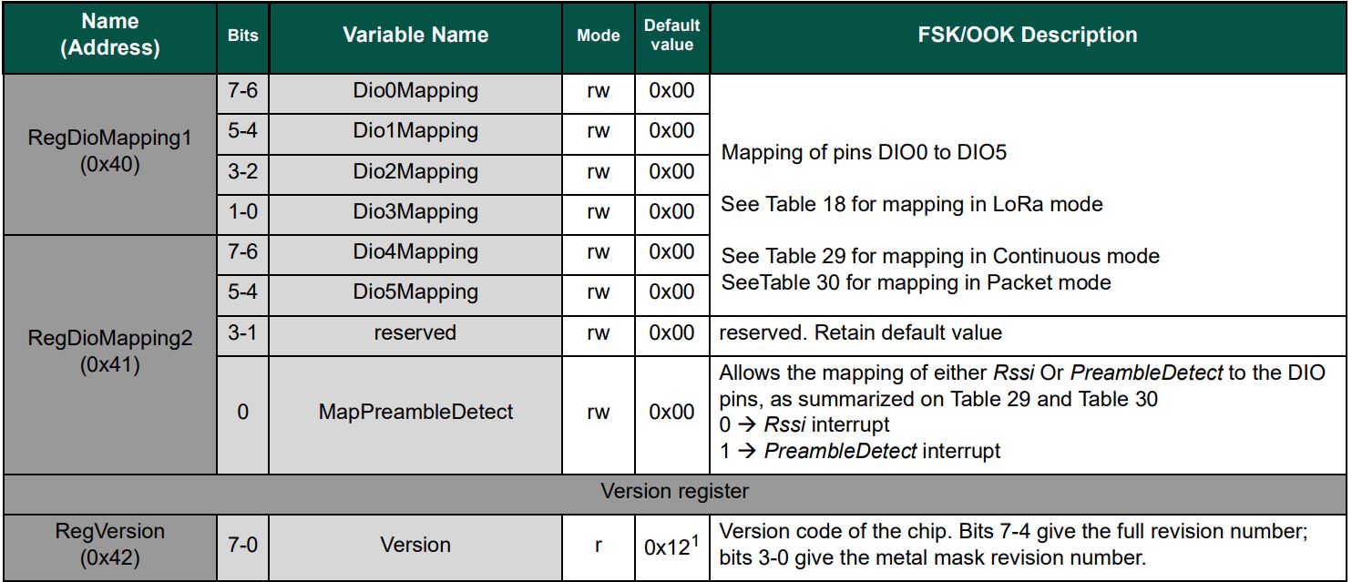
Byte regVersionValue = _registerManager.ReadByte((byte)Configuration.Registers.RegVersion);
if (regVersionValue != Configuration.RegVersionValueExpected)
{
throw new ApplicationException("Semtech SX127X not found");
}
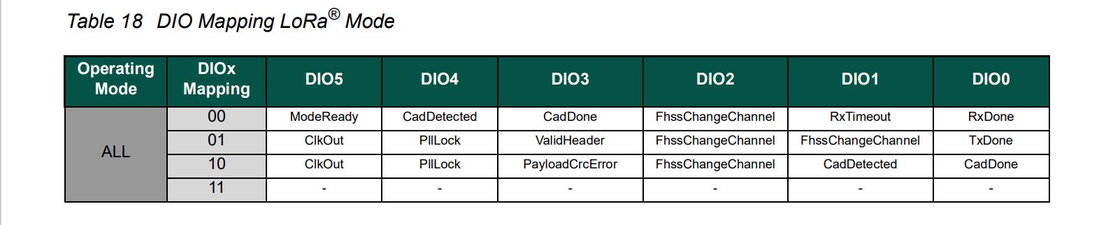
// See Table 18 DIO Mapping LoRa® Mode
Configuration.RegDioMapping1 regDioMapping1Value = Configuration.RegDioMapping1.Dio0None;
regDioMapping1Value |= Configuration.RegDioMapping1.Dio1None;
regDioMapping1Value |= Configuration.RegDioMapping1.Dio2None;
regDioMapping1Value |= Configuration.RegDioMapping1.Dio3None;
_registerManager.WriteByte((byte)Configuration.Registers.RegDioMapping1, (byte)regDioMapping1Value);
// Currently no easy way to test this with available hardware
//Configuration.RegDioMapping2 regDioMapping2Value = Configuration.RegDioMapping2.Dio4None;
//regDioMapping2Value = Configuration.RegDioMapping2.Dio5None;
//_registerManager.WriteByte((byte)Configuration.Registers.RegDioMapping2, (byte)regDioMapping2Value);
// Interrupt pin for RXDone, TXDone, and CadDone notification
_gpioController.OpenPin(dio0Pin, PinMode.InputPullDown);
_gpioController.RegisterCallbackForPinValueChangedEvent(dio0Pin, PinEventTypes.Rising, InterruptGpioPin_ValueChanged);
// RxTimeout, FhssChangeChannel, and CadDetected
if (dio1Pin != 0)
{
_gpioController.OpenPin(dio1Pin, PinMode.InputPullDown);
_gpioController.RegisterCallbackForPinValueChangedEvent(dio1Pin, PinEventTypes.Rising, InterruptGpioPin_ValueChanged);
}
// FhssChangeChannel, FhssChangeChannel, and FhssChangeChannel
if (dio2Pin != 0)
{
_gpioController.OpenPin(dio2Pin, PinMode.InputPullDown);
_gpioController.RegisterCallbackForPinValueChangedEvent(dio2Pin, PinEventTypes.Rising, InterruptGpioPin_ValueChanged);
}
// CadDone, ValidHeader, and PayloadCrcError
if (dio3Pin != 0)
{
_gpioController.OpenPin(dio3Pin, PinMode.InputPullDown);
_gpioController.RegisterCallbackForPinValueChangedEvent(dio3Pin, PinEventTypes.Rising, InterruptGpioPin_ValueChanged);
}
// CadDetected, PllLock and PllLock
if (dio4Pin != 0)
{
_gpioController.OpenPin(dio4Pin, PinMode.InputPullDown);
_gpioController.RegisterCallbackForPinValueChangedEvent(dio4Pin, PinEventTypes.Rising, InterruptGpioPin_ValueChanged);
}
// ModeReady, ClkOut and ClkOut
if (dio5Pin != 0)
{
_gpioController.OpenPin(dio5Pin, PinMode.InputPullDown);
_gpioController.RegisterCallbackForPinValueChangedEvent(dio5Pin, PinEventTypes.Rising, InterruptGpioPin_ValueChanged);
}
}
The same event handler (InterruptGpioPin_ValueChanged) is used for Dio0 thru Dio5. Each event has a “process” method and the RegIrqFlags register controls which one(s) are called.
The RegIrqFlags bits are cleared individually (with regIrqFlagsToClear) at the end of the event handler. Initially I cleared all the flags by writing 0xFF to RegIrqFlags but this caused issues when there were multiple bits set e.g. CadDone along with CadDetected.
It took some experimentation with the SX127xLoRaDeviceClient application to “reliably” trigger events for testing. To generate CAD Detected event, I had to modify one of the Arduino-LoRa sample applications to send messages without a delay, then have it running as the SX127xLoRaDeviceClient application was starting.
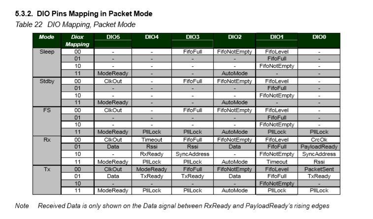
The RFM69CW/RFM69HCW module (based on the Semtech SX1231/SX1231H) has configurable digital outputs (RegDIOMapping1 & RegDIOMapping2) . Which I use to trigger interrupts on my Windows 10 IoT Core or Arduino devices. Currently (Sep 2019) the library only supports the mapping of the digital outputs D0 & D1 when the RFM69 is in Packet Mode.
RegiDIOMapping0 & RegDIOMapping2 settings for DIO thru DIO5
I added some additional constants and enumerations for the other settings configured in RegDioMapping1 & RegDioMapping2.
I had several failed attempts at defining suitable enumerations for configuring the RegDioMapping1 & RegDioMapping2 registers. I initially started with an enumeration for each Mode (Sleep, StandBy etc.) but the implementation was quite complex. The initial version only supports DIO0 & DIO1 as most of the shields I have, only DIO0 adn/or DIO1 are connected.