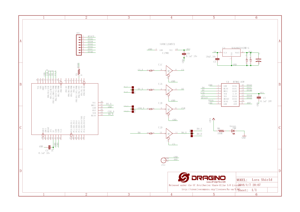
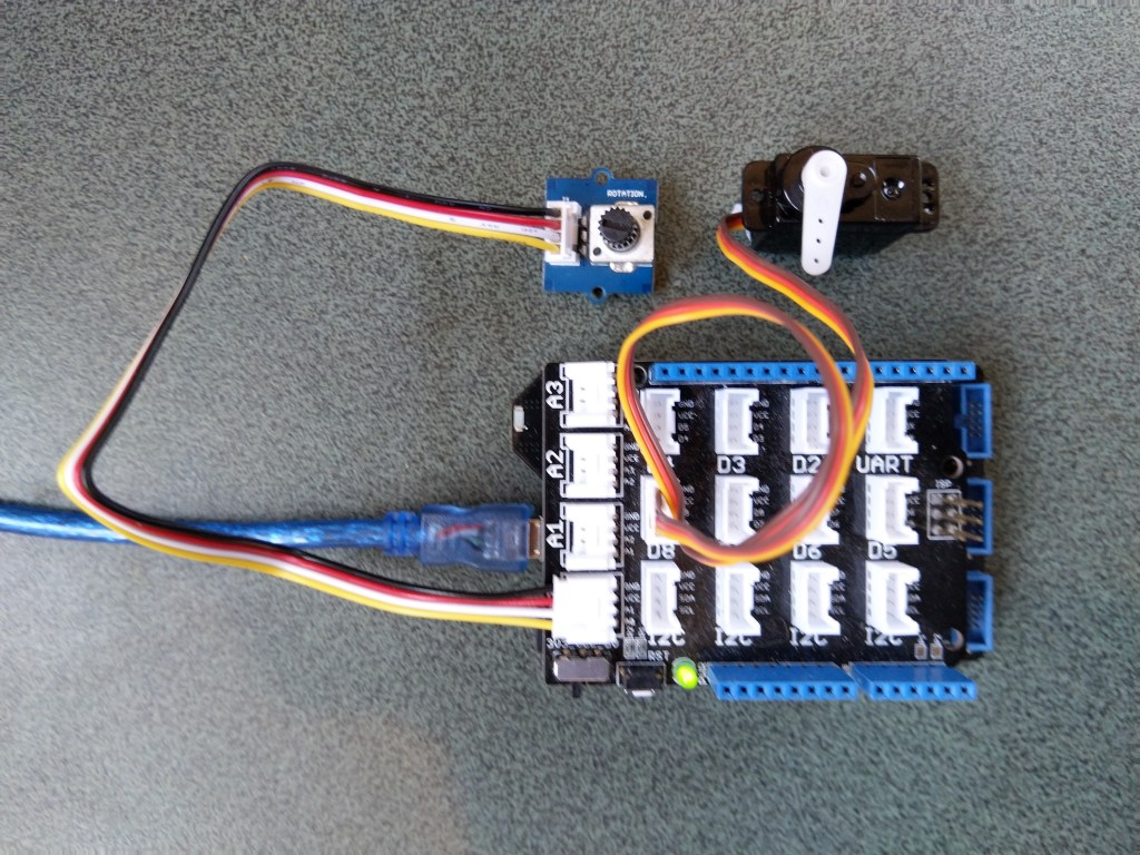
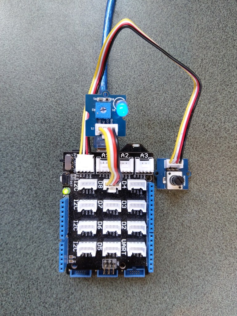
For testing nanoFramework device transmit and receive functionality I used an Arduino/Seeeduino with a Dragino LoRa Shield (running one of the Arduino-LoRa samples) as a client device. This was so I could “bootstrap” connectivity and test interoperability with other libraries/platforms.

I started with transmit as I was confident my Seeeduino + Dragino LoRa Shield could receive messages. The TransmitBasic application puts the device into LoRa + Sleep mode as after reset/powering up the device is in FSK/OOK, Low Frequency + Standby mode).

After loading the message to be sent into the First In First Out(FIFO) buffer, the RegOpMode-Mode is set to Transmit(TX-011), and then the RegIrqFlags register is polled until the TxDone flag is set.

public static void Main()
{
int SendCount = 0;
...
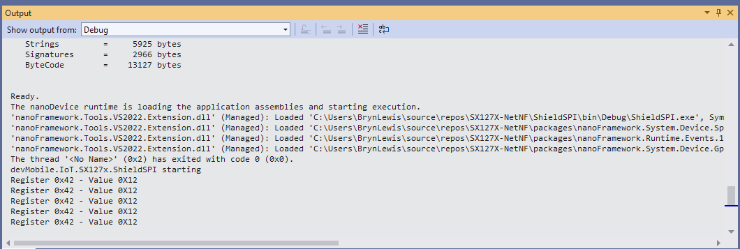
Debug.WriteLine("devMobile.IoT.SX127x.TransmitBasic starting");
try
{
...
#if NETDUINO3_WIFI || ST_STM32F769I_DISCOVERY
SX127XDevice sx127XDevice = new SX127XDevice(SpiBusId, chipSelectLine, resetPinNumber);
#endif
Thread.Sleep(500);
// Put device into LoRa + Standby mode
sx127XDevice.WriteByte(0x01, 0b10000000); // RegOpMode
// Set the frequency to 915MHz
byte[] frequencyBytes = { 0xE4, 0xC0, 0x00 }; // RegFrMsb, RegFrMid, RegFrLsb
sx127XDevice.WriteBytes(0x06, frequencyBytes);
// More power PA Boost
sx127XDevice.WriteByte(0x09, 0b10000000); // RegPaConfig
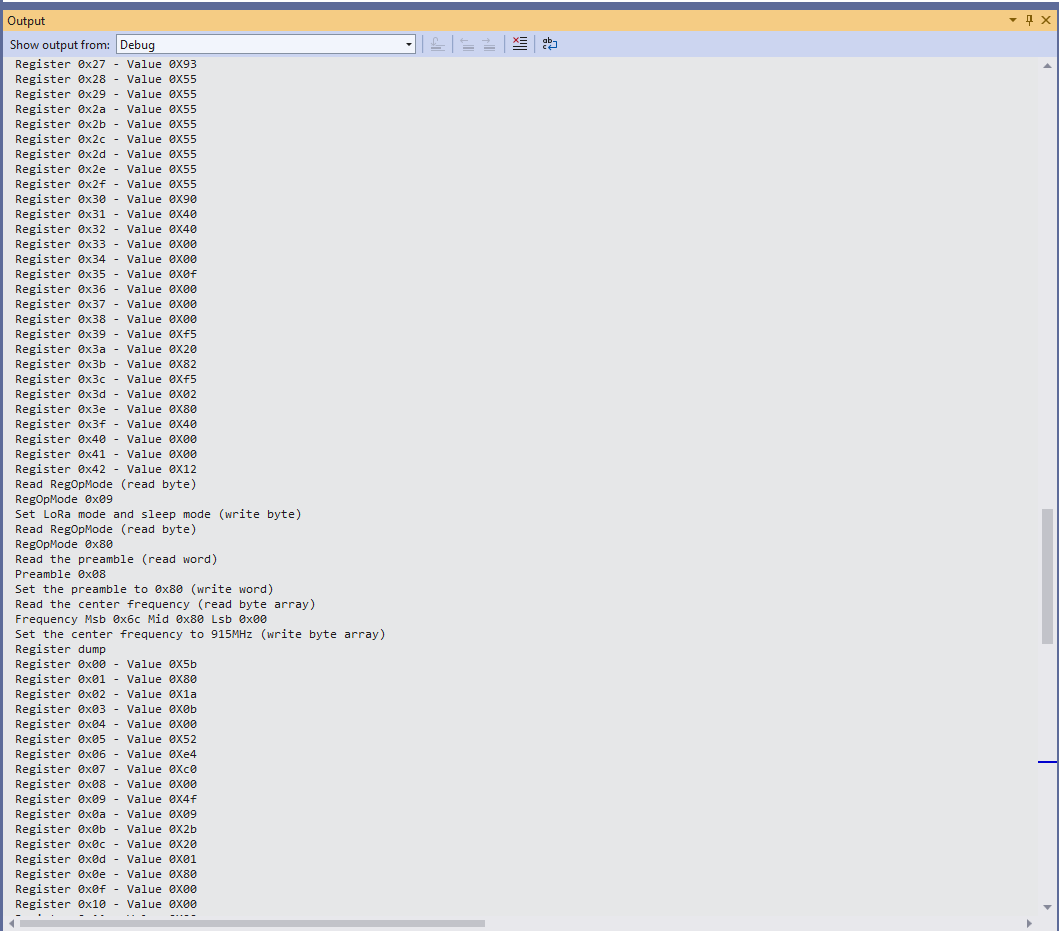
sx127XDevice.RegisterDump();
while (true)
{
sx127XDevice.WriteByte(0x0E, 0x0); // RegFifoTxBaseAddress
// Set the Register Fifo address pointer
sx127XDevice.WriteByte(0x0D, 0x0); // RegFifoAddrPtr
string messageText = $"Hello LoRa from .NET nanoFramework {SendCount += 1}!";
// load the message into the fifo
byte[] messageBytes = UTF8Encoding.UTF8.GetBytes(messageText);
sx127XDevice.WriteBytes(0x0, messageBytes); // RegFifo
// Set the length of the message in the fifo
sx127XDevice.WriteByte(0x22, (byte)messageBytes.Length); // RegPayloadLength
Debug.WriteLine($"Sending {messageBytes.Length} bytes message {messageText}");
// Set the mode to LoRa + Transmit
sx127XDevice.WriteByte(0x01, 0b10000011); // RegOpMode
// Wait until send done, no timeouts in PoC
Debug.WriteLine("Send-wait");
byte irqFlags = sx127XDevice.ReadByte(0x12); // RegIrqFlags
while ((irqFlags & 0b00001000) == 0) // wait until TxDone cleared
{
Thread.Sleep(10);
irqFlags = sx127XDevice.ReadByte(0x12); // RegIrqFlags
Debug.Write(".");
}
Debug.WriteLine("");
sx127XDevice.WriteByte(0x12, 0b00001000); // clear TxDone bit
Debug.WriteLine("Send-Done");
Thread.Sleep(30000);
}
}
catch (Exception ex)
{
Debug.WriteLine(ex.Message);
}
}
}
Once the TransmitBasic application was sending messages reliably I started working on the ReceiveBasic application. As the ReceiveBasic application starts up the SX127X RegOpMode has to be set to sleep/standby so the device can be configured. TOnce that is completed RegOpMode-Mode is set to RxContinuous(101), and the RegIrqFlags register is polled until the RxDone flag is set.
public static void Main()
{
...
Debug.WriteLine("devMobile.IoT.SX127x.ReceiveBasic starting");
try
{
...
#if NETDUINO3_WIFI || ST_STM32F769I_DISCOVERY
SX127XDevice sx127XDevice = new SX127XDevice(SpiBusId, chipSelectLine, resetPinNumber);
#endif
Thread.Sleep(500);
// Put device into LoRa + Sleep mode
sx127XDevice.WriteByte(0x01, 0b10000000); // RegOpMode
// Set the frequency to 915MHz
byte[] frequencyBytes = { 0xE4, 0xC0, 0x00 }; // RegFrMsb, RegFrMid, RegFrLsb
sx127XDevice.WriteBytes(0x06, frequencyBytes);
sx127XDevice.WriteByte(0x0F, 0x0); // RegFifoRxBaseAddress
sx127XDevice.WriteByte(0x01, 0b10000101); // RegOpMode set LoRa & RxContinuous
while (true)
{
// Wait until a packet is received, no timeouts in PoC
Debug.WriteLine("Receive-Wait");
byte irqFlags = sx127XDevice.ReadByte(0x12); // RegIrqFlags
while ((irqFlags & 0b01000000) == 0) // wait until RxDone cleared
{
Thread.Sleep(100);
irqFlags = sx127XDevice.ReadByte(0x12); // RegIrqFlags
Debug.Write(".");
}
Debug.WriteLine("");
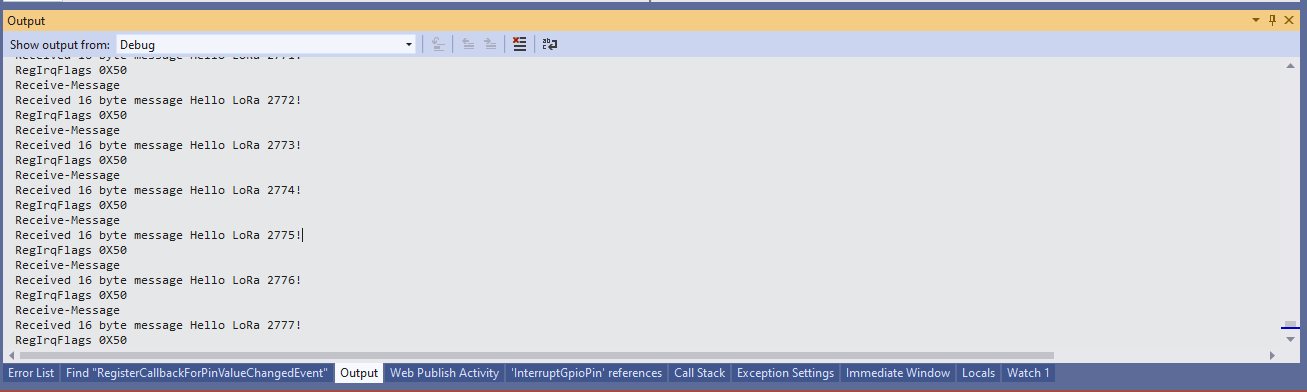
Debug.WriteLine($"RegIrqFlags 0X{irqFlags:X2}");
Debug.WriteLine("Receive-Message");
byte currentFifoAddress = sx127XDevice.ReadByte(0x10); // RegFifiRxCurrent
sx127XDevice.WriteByte(0x0d, currentFifoAddress); // RegFifoAddrPtr
byte numberOfBytes = sx127XDevice.ReadByte(0x13); // RegRxNbBytes
// Read the message from the FIFO
byte[] messageBytes = sx127XDevice.ReadBytes(0x00, numberOfBytes);
sx127XDevice.WriteByte(0x0d, 0);
sx127XDevice.WriteByte(0x12, 0b11111111); // RegIrqFlags clear all the bits
// Remove unprintable characters from messages
for (int index = 0; index < messageBytes.Length; index++)
{
if ((messageBytes[index] < 0x20) || (messageBytes[index] > 0x7E))
{
messageBytes[index] = 0x20;
}
}
string messageText = UTF8Encoding.UTF8.GetString(messageBytes, 0, messageBytes.Length);
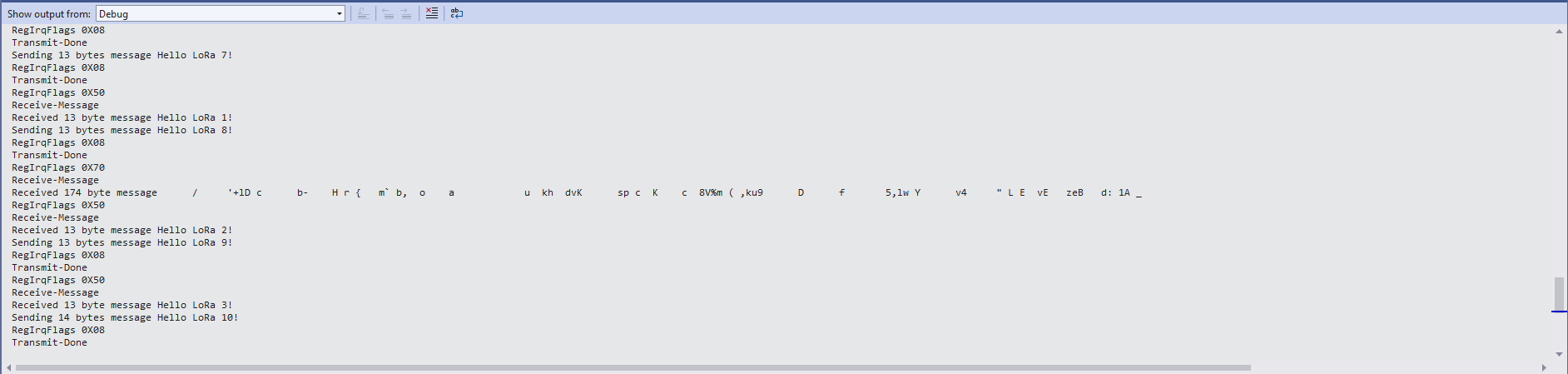
Debug.WriteLine($"Received {messageBytes.Length} byte message {messageText}");
Debug.WriteLine("Receive-Done");
}
}
catch (Exception ex)
{
Debug.WriteLine(ex.Message);
}
}

Every so often the ReceiveBasic application would display a message sent on the same frequency by a device somewhere nearby.
I need to do some more investigation into whether writing 0b00001000 (Transmit) vs. 0b11111111(Receive) to RegIrqFlags is important.