Random wanderings through Microsoft Azure esp. PaaS plumbing, the IoT bits, AI on Micro controllers, AI on Edge Devices, .NET nanoFramework, .NET Core on *nix and ML.NET+ONNX
When developing libraries it’s good to have a selection of different platforms for testing as this can significantly improve the quality and robustness of the implementation. A few months ago I noticed that RAK Wireless have a UWB Module Decawave DW1000 Wisblock so I added one to an order.
I have added a couple of C# processor directives (MAKERFABS_ESP32UWB & RAK11200_RAK1907_RAK13801) so the platform that the Qorvo DW1000 module is running on can be configured.
public class Program
{
#if MAKERFABS_ESP32UWB
    private const int SpiBusId = 1;
    private const int chipSelectLine = Gpio.IO04;
#endif
#if RAK11200_RAK1907_RAK13801
    private const int SpiBusId = 1;
    private const int chipSelectLine = Gpio.IO32;
#endif

    public static void Main()
    {
        Thread.Sleep(5000);

        Debug.WriteLine("devMobile.IoT.Dw1000.ShieldSPI starting");

        try
        {
#if MAKERFABS_ESP32UWB
            Configuration.SetPinFunction(Gpio.IO19, DeviceFunction.SPI1_MISO);
            Configuration.SetPinFunction(Gpio.IO23, DeviceFunction.SPI1_MOSI);
            Configuration.SetPinFunction(Gpio.IO18, DeviceFunction.SPI1_CLOCK);
#endif
#if RAK11200_RAK1907_RAK13801
            Configuration.SetPinFunction(Gpio.IO35, DeviceFunction.SPI1_MISO);
            Configuration.SetPinFunction(Gpio.IO25, DeviceFunction.SPI1_MOSI);
            Configuration.SetPinFunction(Gpio.IO33, DeviceFunction.SPI1_CLOCK);
#endif
            var settings = new SpiConnectionSettings(SpiBusId, chipSelectLine)
            {
                ClockFrequency = 2000000,
                Mode = SpiMode.Mode0,
            };

            using (SpiDevice device = SpiDevice.Create(settings))
            {
                while (true)
                {
                    byte[] writeBuffer = new byte[] { 0x0, 0x0, 0x0, 0x0, 0x0 }; // 0x0 = DEV_ID
                    byte[] readBuffer = new byte[writeBuffer.Length];

                    device.TransferFullDuplex(writeBuffer, readBuffer); // 15, 48, 1, 202, 222

                    uint ridTag = (uint)(readBuffer[4]<< 8 | readBuffer[3]);
                    byte model = readBuffer[2];
                    byte ver = (byte)(readBuffer[1] >> 4);
                    byte rev = (byte)(readBuffer[1] & 0x0f);

                    Debug.WriteLine(String.Format($"RIDTAG 0x{ridTag:X2} MODEL 0x{model:X2} VER 0X{ver:X2} REV 0x{rev:X2}"));

                   Thread.Sleep(10000);
                }
            }
        }
        catch (Exception ex)
        {
            Debug.WriteLine(ex.Message);
        }
    }
}
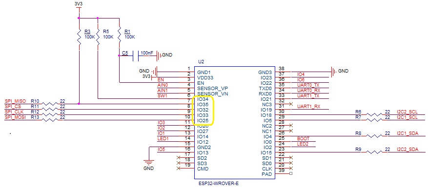
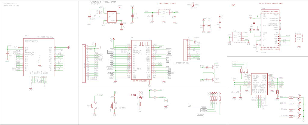
The alignment of the RAK11200 WisBiock Core Module pins and labels on the circuit diagram tripped me up. My initial configuration caused the device to reboot every time the application started.
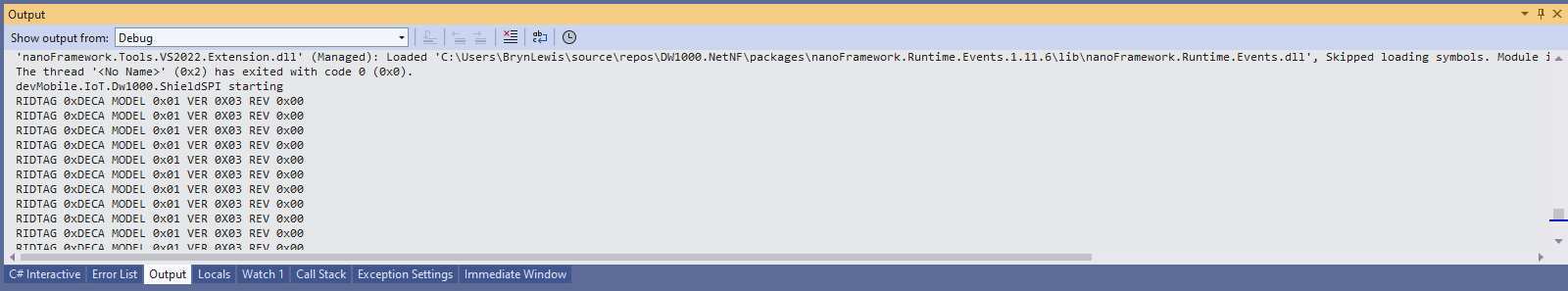
Visual Studio 2022 Debug window displaying the decoded value from Register 0x0
At the top of test applications, I usually have a brief delay i.e Thread.Sleep(5000) so I can attach the debugger or erase the flash before the application crashes.
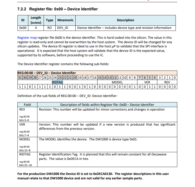
Even though SPI is an industry standard there are often subtle differences which need to be taken into account when reading from/writing to registers. The DW1000 has a static “Device Identifier” which I used to debug my “proof of concept” code.
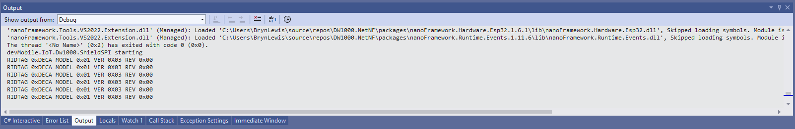
DW1000 Datasheet Register Map documentation for Register 0x00
The DeviceSPI program reads register 0x00 and then displays the decoded payload.
public class Program
{
#if MAKERFABS_ESP32UWB
    private const int SpiBusId = 1;
    private const int chipSelectLine = Gpio.IO04;
#endif

    public static void Main()
    {
        Thread.Sleep(5000);

        Debug.WriteLine("devMobile.IoT.Dw1000.ShieldSPI starting");

        try
        {
#if MAKERFABS_ESP32UWB
            Configuration.SetPinFunction(Gpio.IO19, DeviceFunction.SPI1_MISO);
            Configuration.SetPinFunction(Gpio.IO23, DeviceFunction.SPI1_MOSI);
            Configuration.SetPinFunction(Gpio.IO18, DeviceFunction.SPI1_CLOCK);
#endif
            var settings = new SpiConnectionSettings(SpiBusId, chipSelectLine)
            {
                ClockFrequency = 2000000,
                Mode = SpiMode.Mode0,
            };

            using (SpiDevice device = SpiDevice.Create(settings))
            {
                Thread.Sleep(500);

                while (true)
                {
                    /*
                    byte[] writeBuffer = new byte[] { 0x0, 0x0, 0x0, 0x0, 0x0 }; // 0x0 = DEV_ID
                    byte[] readBuffer = new byte[writeBuffer.Length];

                    device.TransferFullDuplex(writeBuffer, readBuffer); // 15, 48, 1, 202, 222
                    */

                    byte[] writeBuffer = new byte[] { 0x0 }; // 0x0 = DEV_ID
                    byte[] readBuffer = new byte[5];

                    device.TransferFullDuplex(writeBuffer, readBuffer); // 15, 48, 1, 202, 222

                    uint ridTag = (uint)(readBuffer[4]<< 8 | readBuffer[3]);
                    byte model = readBuffer[2];
                    byte ver = (byte)(readBuffer[1] >> 4);
                    byte rev = (byte)(readBuffer[1] & 0x0f);

                    Debug.WriteLine(String.Format($"RIDTAG 0x{ridTag:X2} MODEL 0x{model:X2} VER 0X{ver:X2} REV 0x{rev:X2}"));

                    Thread.Sleep(10000);
                }
            }
        }
        catch (Exception ex)
        {
            Debug.WriteLine(ex.Message);
        }
    }
}
Visual Studio 2022 Debug window displaying the decoded value from Register 0x0
The DW1000 User Manual is > 240 pages, with roughly 140 pages of detailed documentation about the DW1000 register set so progress will be slow.
While “smoke testing” the application I noticed that if I erased the flash, power cycled the device, then ran the application the first execution would fail because the SemtechSX127X could not be detected.
SX127XLoRaDeviceClient first execution startup failure
SX127XLoRaDeviceClient second execution startup success
After printing the code out and reviewing it I noticed that the Configuration.SetPinFunction for the Serial Peripheral Interface(SPI) Master Out Slave In(MOSI), MOSI(Master In Slave Out) and Clock pins was after the opening of the SPI port.
static void Main(string[] args)
{
	byte SendCount = 0;
#if ESP32_WROOM_32_LORA_1_CHANNEL // No reset line for this device as it isn't connected on SX127X
	int chipSelectLine = Gpio.IO16;
	int dio0PinNumber = Gpio.IO26;
#endif
#if NETDUINO3_WIFI
	// Arduino D10->PB10
	int chipSelectLine = PinNumber('B', 10);
	// Arduino D9->PE5
	int resetPinNumber = PinNumber('E', 5);
	// Arduino D2 -PA3
	int dio0PinNumber = PinNumber('A', 3);
#endif
#if ST_STM32F769I_DISCOVERY
	// Arduino D10->PA11
	int chipSelectLine = PinNumber('A', 11);
	// Arduino D9->PH6
	int resetPinNumber = PinNumber('H', 6);
	// Arduino D2->PA4
	int dio0PinNumber = PinNumber('J', 1);
#endif
	Console.WriteLine("devMobile.IoT.SX127xLoRaDevice Range Tester starting");

	try
	{
#f ESP32_WROOM_32_LORA_1_CHANNEL
		Configuration.SetPinFunction(Gpio.IO12, DeviceFunction.SPI1_MISO);
		Configuration.SetPinFunction(Gpio.IO13, DeviceFunction.SPI1_MOSI);
		Configuration.SetPinFunction(Gpio.IO14, DeviceFunction.SPI1_CLOCK);
#endif

		var settings = new SpiConnectionSettings(SpiBusId, chipSelectLine)
		{
			ClockFrequency = 1000000,
			Mode = SpiMode.Mode0,// From SemTech docs pg 80 CPOL=0, CPHA=0
			SharingMode = SpiSharingMode.Shared
		};

		using (_gpioController = new GpioController())
		using (SpiDevice spiDevice = new SpiDevice(settings))
		{

#if ESP32_WROOM_32_LORA_1_CHANNEL
			_sx127XDevice = new SX127XDevice(spiDevice, _gpioController, dio0Pin: dio0PinNumber);
#endif

#if NETDUINO3_WIFI || ST_STM32F769I_DISCOVERY
			_sx127XDevice = new SX127XDevice(spiDevice, _gpioController, dio0Pin: dio0PinNumber, resetPin:resetPinNumber);
#endif
...

		}
		catch (Exception ex)
		{
				Console.WriteLine(ex.Message);
		}
	}
I assume that the first execution after erasing the flash and power cycling the device, the SPI port pin assignments were not configured when the port was opened, then on the next execution the port was pre-configured.
The RangeTester application flashes on onboard Light Emitting Diode(LED) every time a valid message is received. But, on the ESP32 it turned on when the first message arrived and didn’t turn off. After discussion on the nanoFramework Discord this has been identified as an issue(May 2022).
The TransmitInterrupt application loads the message to be sent into the First In First Out(FIFO) buffer, RegDioMapping1 is set to interrupt onTxDone(PacketSent-00), then RegRegOpMode-Mode is set to Transmit. When the message has been sent InterruptGpioPin_ValueChanged is called, and the TxDone(0b00001000) flag is set in the RegIrqFlags register.
The ReceiveInterrupt application sets the RegDioMapping1 to interrupt on RxDone(PacketReady-00), then the RegRegOpMode-Mode is set to Receive(TX-101). When a message is received InterruptGpioPin_ValueChanged is called, with the RxDone(0b00001000) flag set in the RegIrqFlags register, and then the message is read from First In First Out(FIFO) buffer.
namespace devMobile.IoT.SX127x.ReceiveTransmitInterrupt
{
...
   public sealed class SX127XDevice
   {
...
      public SX127XDevice(int busId, int chipSelectLine, int interruptPin, int resetPin)
      {
         var settings = new SpiConnectionSettings(busId, chipSelectLine)
         {
            ClockFrequency = 1000000,
            Mode = SpiMode.Mode0,// From SemTech docs pg 80 CPOL=0, CPHA=0
            SharingMode = SpiSharingMode.Shared
         };

         SX127XTransceiver = new SpiDevice(settings);

         GpioController gpioController = new GpioController();


         // Factory reset pin configuration
         gpioController.OpenPin(resetPin, PinMode.Output);

         gpioController.Write(resetPin, PinValue.Low);
         Thread.Sleep(20);
         gpioController.Write(resetPin, PinValue.High);
         Thread.Sleep(20);

         // Interrupt pin for RX message & TX done notification
         gpioController.OpenPin(interruptPin, PinMode.InputPullDown);

         gpioController.RegisterCallbackForPinValueChangedEvent(interruptPin, PinEventTypes.Rising, InterruptGpioPin_ValueChanged);
      }
...
   }

      private void InterruptGpioPin_ValueChanged(object sender, PinValueChangedEventArgs e)
      {
         byte irqFlags = this.ReadByte(0x12); // RegIrqFlags
         Debug.WriteLine($"RegIrqFlags 0X{irqFlags:x2}");

         if ((irqFlags & 0b01000000) == 0b01000000)  // RxDone
         {
            Debug.WriteLine("Receive-Message");
            byte currentFifoAddress = this.ReadByte(0x10); // RegFifiRxCurrent
            this.WriteByte(0x0d, currentFifoAddress); // RegFifoAddrPtr

            byte numberOfBytes = this.ReadByte(0x13); // RegRxNbBytes

            // Allocate buffer for message
            byte[] messageBytes = this.ReadBytes(0X0, numberOfBytes);

            // Remove unprintable characters from messages
            for (int index = 0; index < messageBytes.Length; index++)
            {
               if ((messageBytes[index] < 0x20) || (messageBytes[index] > 0x7E))
               {
                  messageBytes[index] = 0x20;
               }
            }

            string messageText = UTF8Encoding.UTF8.GetString(messageBytes, 0, messageBytes.Length);
            Debug.WriteLine($"Received {messageBytes.Length} byte message {messageText}");
         }

         if ((irqFlags & 0b00001000) == 0b00001000)  // TxDone
         {
            this.WriteByte(0x01, 0b10000101); // RegOpMode set LoRa & RxContinuous
            Debug.WriteLine("Transmit-Done");
         }

         this.WriteByte(0x40, 0b00000000); // RegDioMapping1 0b00000000 DI0 RxReady & TxReady
         this.WriteByte(0x12, 0xff);// RegIrqFlags
      }

   public class Program
   {
...
   #if NETDUINO3_WIFI
      private const int SpiBusId = 2;
#endif
...

      public static void Main()
      {
         int SendCount = 0;
...
#if NETDUINO3_WIFI
         // Arduino D10->PB10
         int chipSelectLine = PinNumber('B', 10);
         // Arduino D9->PE5
         int resetPinNumber = PinNumber('E', 5);
         // Arduino D2 -PA3
         int interruptPinNumber = PinNumber('A', 3);
#endif
...

       Debug.WriteLine("devMobile.IoT.SX127x.ReceiveTransmitInterrupt starting");

         try
         {
...
#if NETDUINO3_WIFI || ST_STM32F769I_DISCOVERY
            SX127XDevice sx127XDevice = new SX127XDevice(SpiBusId, chipSelectLine, interruptPinNumber, resetPinNumber);
#endif
            Thread.Sleep(500);

            // Put device into LoRa + Sleep mode
            sx127XDevice.WriteByte(0x01, 0b10000000); // RegOpMode

            // Set the frequency to 915MHz
            byte[] frequencyWriteBytes = { 0xE4, 0xC0, 0x00 }; // RegFrMsb, RegFrMid, RegFrLsb
            sx127XDevice.WriteBytes(0x06, frequencyWriteBytes);

            // More power PA Boost
            sx127XDevice.WriteByte(0x09, 0b10000000); // RegPaConfig

            sx127XDevice.WriteByte(0x01, 0b10000101); // RegOpMode set LoRa & RxContinuous

            while (true)
            {
               // Set the Register Fifo address pointer
               sx127XDevice.WriteByte(0x0E, 0x00); // RegFifoTxBaseAddress

               // Set the Register Fifo address pointer
               sx127XDevice.WriteByte(0x0D, 0x0); // RegFifoAddrPtr

               string messageText = $"Hello LoRa {SendCount += 1}!";

               // load the message into the fifo
               byte[] messageBytes = UTF8Encoding.UTF8.GetBytes(messageText);
               sx127XDevice.WriteBytes(0x0, messageBytes); // RegFifo

               // Set the length of the message in the fifo
               sx127XDevice.WriteByte(0x22, (byte)messageBytes.Length); // RegPayloadLength
               sx127XDevice.WriteByte(0x40, 0b01000000); // RegDioMapping1 0b00000000 DI0 RxReady & TxReady
               sx127XDevice.WriteByte(0x01, 0b10000011); // RegOpMode

               Debug.WriteLine($"Sending {messageBytes.Length} bytes message {messageText}");

               Thread.Sleep(10000);
            }
         }
         catch (Exception ex)
         {
            Debug.WriteLine(ex.Message);
         }
      }
...
   }
}
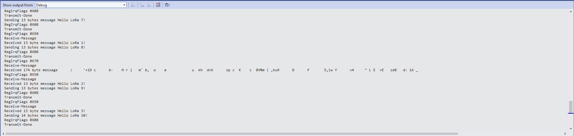
ReceiveTransmitInterrupt application output
The ReceiveTransmitInterrupt application combines the functionality TransmitInterrupt and ReceiveInterrupt programs. The key differences are the RegDioMapping1 setup and in InterruptGpioPin_ValueChanged where the TxDone & RxDone flags in the RegIrqFlags register specify how the interrupt is handled.
For testing nanoFramework device transmit and receive functionality I used an Arduino/Seeeduino with a Dragino LoRa Shield (running one of the Arduino-LoRa samples) as a client device. This was so I could “bootstrap” connectivity and test interoperability with other libraries/platforms.
Arduino/Netduino devices for .NET nanoFramework interoperability test-rig
I started with transmit as I was confident my Seeeduino + Dragino LoRa Shield could receive messages. The TransmitBasic application puts the device into LoRa + Sleep mode as after reset/powering up the device is in FSK/OOK, Low Frequency + Standby mode).
SX127X RegOpMode options
After loading the message to be sent into the First In First Out(FIFO) buffer, the RegOpMode-Mode is set to Transmit(TX-011), and then the RegIrqFlags register is polled until the TxDone flag is set.
SX127X ReqIrqFlags options
public static void Main()
{
  int SendCount = 0;
...
  Debug.WriteLine("devMobile.IoT.SX127x.TransmitBasic starting");

   try
   {
...
#if NETDUINO3_WIFI || ST_STM32F769I_DISCOVERY
      SX127XDevice sx127XDevice = new SX127XDevice(SpiBusId, chipSelectLine, resetPinNumber);
#endif
     Thread.Sleep(500);

     // Put device into LoRa + Standby mode
     sx127XDevice.WriteByte(0x01, 0b10000000); // RegOpMode

      // Set the frequency to 915MHz
      byte[] frequencyBytes = { 0xE4, 0xC0, 0x00 }; // RegFrMsb, RegFrMid, RegFrLsb
      sx127XDevice.WriteBytes(0x06, frequencyBytes);

      // More power PA Boost
      sx127XDevice.WriteByte(0x09, 0b10000000); // RegPaConfig

      sx127XDevice.RegisterDump();

      while (true)
      {
         sx127XDevice.WriteByte(0x0E, 0x0); // RegFifoTxBaseAddress

         // Set the Register Fifo address pointer
         sx127XDevice.WriteByte(0x0D, 0x0); // RegFifoAddrPtr

         string messageText = $"Hello LoRa from .NET nanoFramework {SendCount += 1}!";

         // load the message into the fifo
         byte[] messageBytes = UTF8Encoding.UTF8.GetBytes(messageText);
         sx127XDevice.WriteBytes(0x0, messageBytes); // RegFifo

         // Set the length of the message in the fifo
         sx127XDevice.WriteByte(0x22, (byte)messageBytes.Length); // RegPayloadLength

         Debug.WriteLine($"Sending {messageBytes.Length} bytes message {messageText}");
         // Set the mode to LoRa + Transmit
         sx127XDevice.WriteByte(0x01, 0b10000011); // RegOpMode

         // Wait until send done, no timeouts in PoC
         Debug.WriteLine("Send-wait");
         byte irqFlags = sx127XDevice.ReadByte(0x12); // RegIrqFlags
         while ((irqFlags & 0b00001000) == 0)  // wait until TxDone cleared
         {
            Thread.Sleep(10);
            irqFlags = sx127XDevice.ReadByte(0x12); // RegIrqFlags
            Debug.Write(".");
         }
         Debug.WriteLine("");
         sx127XDevice.WriteByte(0x12, 0b00001000); // clear TxDone bit
         Debug.WriteLine("Send-Done");

         Thread.Sleep(30000);
         }
      }
      catch (Exception ex)
      {
         Debug.WriteLine(ex.Message);
      }
   }
}
Transmit Basic application output
Once the TransmitBasic application was sending messages reliably I started working on the ReceiveBasic application. As the ReceiveBasic application starts up the SX127X RegOpMode has to be set to sleep/standby so the device can be configured. TOnce that is completed RegOpMode-Mode is set to RxContinuous(101), and the RegIrqFlags register is polled until the RxDone flag is set.
public static void Main()
{
...
   Debug.WriteLine("devMobile.IoT.SX127x.ReceiveBasic starting");

   try
   {
...
#if NETDUINO3_WIFI || ST_STM32F769I_DISCOVERY
      SX127XDevice sx127XDevice = new SX127XDevice(SpiBusId, chipSelectLine, resetPinNumber);
#endif
      Thread.Sleep(500);

      // Put device into LoRa + Sleep mode
      sx127XDevice.WriteByte(0x01, 0b10000000); // RegOpMode

      // Set the frequency to 915MHz
      byte[] frequencyBytes = { 0xE4, 0xC0, 0x00 }; // RegFrMsb, RegFrMid, RegFrLsb
      sx127XDevice.WriteBytes(0x06, frequencyBytes);

      sx127XDevice.WriteByte(0x0F, 0x0); // RegFifoRxBaseAddress

      sx127XDevice.WriteByte(0x01, 0b10000101); // RegOpMode set LoRa & RxContinuous

       while (true)
       {
          // Wait until a packet is received, no timeouts in PoC
         Debug.WriteLine("Receive-Wait");
         byte irqFlags = sx127XDevice.ReadByte(0x12); // RegIrqFlags
         while ((irqFlags & 0b01000000) == 0)  // wait until RxDone cleared
         {
            Thread.Sleep(100);
            irqFlags = sx127XDevice.ReadByte(0x12); // RegIrqFlags
            Debug.Write(".");
         }
         Debug.WriteLine("");
         Debug.WriteLine($"RegIrqFlags 0X{irqFlags:X2}");
         Debug.WriteLine("Receive-Message");
         byte currentFifoAddress = sx127XDevice.ReadByte(0x10); // RegFifiRxCurrent
         sx127XDevice.WriteByte(0x0d, currentFifoAddress); // RegFifoAddrPtr

         byte numberOfBytes = sx127XDevice.ReadByte(0x13); // RegRxNbBytes

         // Read the message from the FIFO
         byte[] messageBytes = sx127XDevice.ReadBytes(0x00, numberOfBytes);

         sx127XDevice.WriteByte(0x0d, 0);
         sx127XDevice.WriteByte(0x12, 0b11111111); // RegIrqFlags clear all the bits

         // Remove unprintable characters from messages
         for (int index = 0; index < messageBytes.Length; index++)
         {
            if ((messageBytes[index] < 0x20) || (messageBytes[index] > 0x7E))
            {
               messageBytes[index] = 0x20;
            }
         }

         string messageText = UTF8Encoding.UTF8.GetString(messageBytes, 0, messageBytes.Length);
         Debug.WriteLine($"Received {messageBytes.Length} byte message {messageText}");

         Debug.WriteLine("Receive-Done");
      }
    }
   catch (Exception ex)
   {
      Debug.WriteLine(ex.Message);
   }
}
Receive Basic application output
Every so often the ReceiveBasic application would display a message sent on the same frequency by a device somewhere nearby.
ReceiveBasic application messages from unknown source
I need to do some more investigation into whether writing 0b00001000 (Transmit) vs. 0b11111111(Receive) to RegIrqFlags is important.
Now that I could reliably dump all the Dragino shield registers I wanted to be able to configure the Semtech 127X device and reset it back to factory settings. A factory reset is done by strobing the SX127X reset pin.
SX127X Reset timing diagram
SX127X Reset process
To support this I added a constructor with an additional parameter for the reset General Purpose Input Output(GPIO) pin number to the SX127XDevice class. The original constructor was retained as the SX127X reset pin is not connected on the SparkFun LoRa Gateway-1-Channel (ESP32) and a limited number of other devices.
namespace devMobile.IoT.SX127x.RegisterReadAndWrite
{
using System;
using System.Diagnostics;
using System.Threading;
using System.Device.Gpio;
using System.Device.Spi;
#if ESP32_WROOM_32_LORA_1_CHANNEL
using nanoFramework.Hardware.Esp32;
#endif
public sealed class SX127XDevice
{
private const byte RegisterAddressMinimum = 0X0;
private const byte RegisterAddressMaximum = 0x42;
private const byte RegisterAddressReadMask = 0X7f;
private const byte RegisterAddressWriteMask = 0x80;
private readonly SpiDevice SX127XTransceiver;
public SX127XDevice(int busId, int chipSelectLine, int resetPin)
{
var settings = new SpiConnectionSettings(busId, chipSelectLine)
{
ClockFrequency = 1000000,
Mode = SpiMode.Mode0,// From SemTech docs pg 80 CPOL=0, CPHA=0
SharingMode = SpiSharingMode.Shared
};
SX127XTransceiver = new SpiDevice(settings);
// Factory reset pin configuration
GpioController gpioController = new GpioController();
gpioController.OpenPin(resetPin, PinMode.Output);
gpioController.Write(resetPin, PinValue.Low);
Thread.Sleep(20);
gpioController.Write(resetPin, PinValue.High);
Thread.Sleep(20);
}
public SX127XDevice(int busId, int chipSelectLine)
{
var settings = new SpiConnectionSettings(busId, chipSelectLine)
{
ClockFrequency = 1000000,
Mode = SpiMode.Mode0,// From SemTech docs pg 80 CPOL=0, CPHA=0
SharingMode = SpiSharingMode.Shared,
};
SX127XTransceiver = new SpiDevice(settings);
}
public Byte ReadByte(byte registerAddress)
{
byte[] writeBuffer = new byte[] { registerAddress &= RegisterAddressReadMask, 0x0 };
byte[] readBuffer = new byte[writeBuffer.Length];
SX127XTransceiver.TransferFullDuplex(writeBuffer, readBuffer);
return readBuffer[1];
}
public ushort ReadWord(byte address)
{
byte[] writeBuffer = new byte[] { address &= RegisterAddressReadMask, 0x0, 0x0 };
byte[] readBuffer = new byte[writeBuffer.Length];
SX127XTransceiver.TransferFullDuplex(writeBuffer, readBuffer);
return (ushort)(readBuffer[2] + (readBuffer[1] << 8));
}
public ushort ReadWordMsbLsb(byte address)
{
byte[] writeBuffer = new byte[] { address &= RegisterAddressReadMask, 0x0, 0x0 };
byte[] readBuffer = new byte[writeBuffer.Length];
SX127XTransceiver.TransferFullDuplex(writeBuffer, readBuffer);
return (ushort)((readBuffer[1] << 8) + readBuffer[2]);
}
public byte[] ReadBytes(byte address, byte length)
{
byte[] writeBuffer = new byte[length + 1];
byte[] readBuffer = new byte[writeBuffer.Length];
byte[] replyBuffer = new byte[length];
writeBuffer[0] = address &= RegisterAddressReadMask;
SX127XTransceiver.TransferFullDuplex(writeBuffer, readBuffer);
Array.Copy(readBuffer, 1, replyBuffer, 0, length);
return replyBuffer;
}
public void WriteByte(byte address, byte value)
{
byte[] writeBuffer = new byte[] { address |= RegisterAddressWriteMask, value };
byte[] readBuffer = new byte[writeBuffer.Length];
SX127XTransceiver.TransferFullDuplex(writeBuffer, readBuffer);
}
public void WriteWord(byte address, ushort value)
{
byte[] valueBytes = BitConverter.GetBytes(value);
byte[] writeBuffer = new byte[] { address |= RegisterAddressWriteMask, valueBytes[0], valueBytes[1] };
byte[] readBuffer = new byte[writeBuffer.Length];
SX127XTransceiver.TransferFullDuplex(writeBuffer, readBuffer);
}
public void WriteWordMsbLsb(byte address, ushort value)
{
byte[] valueBytes = BitConverter.GetBytes(value);
byte[] writeBuffer = new byte[] { address |= RegisterAddressWriteMask, valueBytes[1], valueBytes[0] };
byte[] readBuffer = new byte[writeBuffer.Length];
SX127XTransceiver.TransferFullDuplex(writeBuffer, readBuffer);
}
public void WriteBytes(byte address, byte[] bytes)
{
byte[] writeBuffer = new byte[1 + bytes.Length];
byte[] readBuffer = new byte[writeBuffer.Length];
Array.Copy(bytes, 0, writeBuffer, 1, bytes.Length);
writeBuffer[0] = address |= RegisterAddressWriteMask;
SX127XTransceiver.TransferFullDuplex(writeBuffer, readBuffer);
}
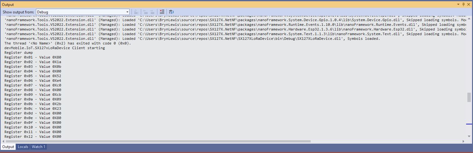
public void RegisterDump()
{
Debug.WriteLine("Register dump");
for (byte registerIndex = RegisterAddressMinimum; registerIndex <= RegisterAddressMaximum; registerIndex++)
{
byte registerValue = this.ReadByte(registerIndex);
Debug.WriteLine($"Register 0x{registerIndex:x2} - Value 0X{registerValue:x2}");
}
Debug.WriteLine("");
}
}
public class Program
{
#if ESP32_WROOM_32_LORA_1_CHANNEL
private const int SpiBusId = 1;
#endif
#if NETDUINO3_WIFI
private const int SpiBusId = 2;
#endif
#if ST_STM32F769I_DISCOVERY
private const int SpiBusId = 2;
#endif
public static void Main()
{
byte[] frequencyBytes;
#if ESP32_WROOM_32_LORA_1_CHANNEL // No reset line for this device as it isn't connected on SX127X
int chipSelectLine = Gpio.IO16;
#endif
#if NETDUINO3_WIFI
// Arduino D10->PB10
int chipSelectLine = PinNumber('B', 10);
// Arduino D9->PE5
int resetPinNumber = PinNumber('E', 5);
#endif
#if ST_STM32F769I_DISCOVERY
// Arduino D10->PA11
int chipSelectLine = PinNumber('A', 11);
// Arduino D9->PH6
int resetPinNumber = PinNumber('H', 6);
#endif
Debug.WriteLine("devMobile.IoT.SX127x.RegisterReadAndWrite starting");
try
{
#if ESP32_WROOM_32_LORA_1_CHANNEL
Configuration.SetPinFunction(Gpio.IO12, DeviceFunction.SPI1_MISO);
Configuration.SetPinFunction(Gpio.IO13, DeviceFunction.SPI1_MOSI);
Configuration.SetPinFunction(Gpio.IO14, DeviceFunction.SPI1_CLOCK);
SX127XDevice sx127XDevice = new SX127XDevice(SpiBusId, chipSelectLine);
#endif
#if NETDUINO3_WIFI || ST_STM32F769I_DISCOVERY
SX127XDevice sx127XDevice = new SX127XDevice(SpiBusId, chipSelectLine, resetPinNumber);
#endif
Thread.Sleep(500);
sx127XDevice.RegisterDump();
while (true)
{
Debug.WriteLine("Read RegOpMode (read byte)");
Byte regOpMode1 = sx127XDevice.ReadByte(0x1);
Debug.WriteLine($"RegOpMode 0x{regOpMode1:x2}");
Debug.WriteLine("Set LoRa mode and sleep mode (write byte)");
sx127XDevice.WriteByte(0x01, 0b10000000);
Debug.WriteLine("Read RegOpMode (read byte)");
Byte regOpMode2 = sx127XDevice.ReadByte(0x1);
Debug.WriteLine($"RegOpMode 0x{regOpMode2:x2}");
Debug.WriteLine("Read the preamble (read word)");
ushort preamble = sx127XDevice.ReadWord(0x20);
Debug.WriteLine($"Preamble 0x{preamble:x2}");
Console.WriteLine("Read the preamble (read word)"); // Should be 0x08
preamble = sx127XDevice.ReadWordMsbLsb(0x20);
Debug.WriteLine($"Preamble 0x{preamble:x2}");
Debug.WriteLine("Read the centre frequency (read byte array)");
frequencyBytes = sx127XDevice.ReadBytes(0x06, 3);
Debug.WriteLine($"Frequency Msb 0x{frequencyBytes[0]:x2} Mid 0x{frequencyBytes[1]:x2} Lsb 0x{frequencyBytes[2]:x2}");
Debug.WriteLine("Set the centre frequency to 915MHz (write byte array)");
byte[] frequencyWriteBytes = { 0xE4, 0xC0, 0x00 };
sx127XDevice.WriteBytes(0x06, frequencyWriteBytes);
Debug.WriteLine("Read the centre frequency (read byte array)");
frequencyBytes = sx127XDevice.ReadBytes(0x06, 3);
Debug.WriteLine($"Frequency Msb 0x{frequencyBytes[0]:x2} Mid 0x{frequencyBytes[1]:x2} Lsb 0x{frequencyBytes[2]:x2}");
sx127XDevice.RegisterDump();
Thread.Sleep(30000);
}
}
catch (Exception ex)
{
Debug.WriteLine(ex.Message);
}
}
#if NETDUINO3_WIFI || ST_STM32F769I_DISCOVERY
static int PinNumber(char port, byte pin)
{
if (port < 'A' || port > 'J')
throw new ArgumentException();
return ((port - 'A') * 16) + pin;
}
#endif
}
}
The PinNumber helper is more user friendly that the raw numbers and is “inspired” by sample .NET nanoFramework General Purpose Input Output(GPIO) sample code.
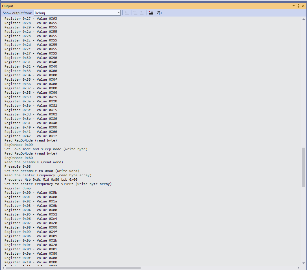
Each method was tested by read/writing suitable register(s) in the device configuration (Needed to set it into LoRa mode first).
The next step is to extract the Serial Peripheral Interface(SPI) register access functionality into a module and configure the bare minimum of settings required to get the SX127X to receive and transmit messages.