Random wanderings through Microsoft Azure esp. PaaS plumbing, the IoT bits, AI on Micro controllers, AI on Edge Devices, .NET nanoFramework, .NET Core on *nix and ML.NET+ONNX
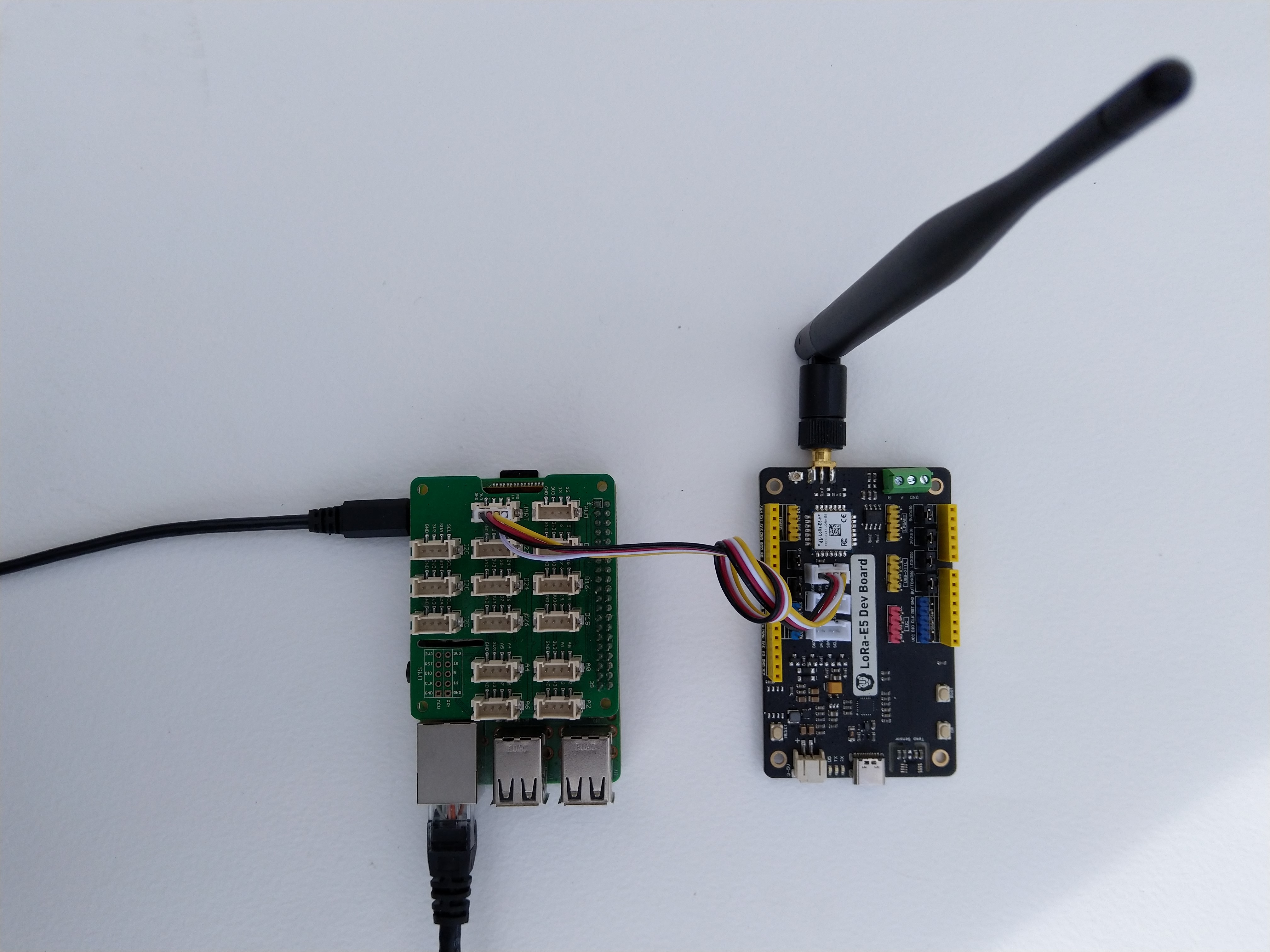
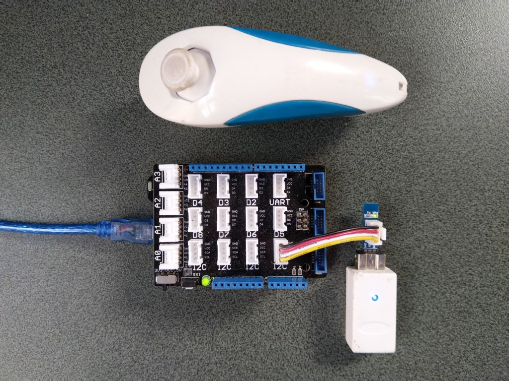
Seeed LoRa-E5 Development kit connected to Gove bas shield on a Raspberry PI3
My Over the Air Activation (OTAA) implementation is very “nasty” I have assumed that there would be no timeouts or failures and I only send one BCD message “48656c6c6f204c6f526157414e” which is “hello LoRaWAN”.
The code just sequentially steps through the necessary configuration to join the TTN network with a suitable delay after each command is sent. There also appeared to be quite a variation in response times, especially for joining the network(most probably network related) and the progress of sending a message.
//---------------------------------------------------------------------------------
// Copyright (c) September 2021, devMobile Software
//
// Licensed under the Apache License, Version 2.0 (the "License");
// you may not use this file except in compliance with the License.
// You may obtain a copy of the License at
//
//     http://www.apache.org/licenses/LICENSE-2.0
//
// Unless required by applicable law or agreed to in writing, software
// distributed under the License is distributed on an "AS IS" BASIS,
// WITHOUT WARRANTIES OR CONDITIONS OF ANY KIND, either express or implied.
// See the License for the specific language governing permissions and
// limitations under the License.
//
//---------------------------------------------------------------------------------
namespace devMobile.IoT.NetCore.SeeedLoRaE5.NetworkJoinOTAA
{
	using System;
	using System.Diagnostics;
	using System.IO.Ports;
	using System.Threading;

	class Program
	{
		private const string SerialPortId = "/dev/ttyS0";

		private const string AppKey = "................................";
		private const string AppEui = "................";

		private const byte MessagePort = 15;

		//private const string Payload = "48656c6c6f204c6f526157414e"; // Hello LoRaWAN
		private const string Payload = "01020304"; // AQIDBA==
		//private const string Payload = "04030201"; // BAMCAQ==

		public static void Main()
		{
			string response;

			Debug.WriteLine("devMobile.IoT.SeeedLoRaE5.NetworkJoinOTAA starting");

			Debug.WriteLine(String.Join(",", SerialPort.GetPortNames()));

			try
			{
				using (SerialPort serialDevice = new SerialPort(SerialPortId))
				{
					// set parameters
					serialDevice.BaudRate = 9600;
					serialDevice.Parity = Parity.None;
					serialDevice.StopBits = StopBits.One;
					serialDevice.Handshake = Handshake.None;
					serialDevice.DataBits = 8;

					serialDevice.ReadTimeout = 10000;

					serialDevice.NewLine = "\r\n";

					serialDevice.Open();

					// clear out the RX buffer
					serialDevice.ReadExisting();
					response = serialDevice.ReadExisting();
					Debug.WriteLine($"Response :{response.Trim()} bytes:{response.Length}");
					Thread.Sleep(500);

					// Set the Region to AS923
					serialDevice.WriteLine("AT+DR=AS923\r\n");
					response = serialDevice.ReadLine();
					Debug.WriteLine($"Response :{response.Trim()} bytes:{response.Length}");

					// Set the Join mode
					serialDevice.WriteLine("AT +MODE=LWOTAA\r\n");
					response = serialDevice.ReadLine();
					Debug.WriteLine($"Response :{response.Trim()} bytes:{response.Length}");

					// Set the appEUI
					serialDevice.WriteLine($"AT+ID=AppEui,\"{AppEui}\"\r\n");
					response = serialDevice.ReadLine();
					Debug.WriteLine($"Response :{response.Trim()} bytes:{response.Length}");

					// Set the appKey
					serialDevice.WriteLine($"AT+KEY=APPKEY,{AppKey}\r\n");
					response = serialDevice.ReadLine();
					Debug.WriteLine($"Response :{response.Trim()} bytes:{response.Length}");

					// Set the port number
					serialDevice.WriteLine($"AT+PORT={MessagePort}\r\n");
					response = serialDevice.ReadLine();
					Debug.WriteLine($"Response :{response.Trim()} bytes:{response.Length}");

					// Join the network
					serialDevice.WriteLine("AT+JOIN\r\n");

					// Join start
					response = serialDevice.ReadLine();
					Debug.WriteLine($"Response :{response.Trim()} bytes:{response.Length}");

					// JOIN normal
					response = serialDevice.ReadLine();
					Debug.WriteLine($"Response :{response.Trim()} bytes:{response.Length}");

					Thread.Sleep(5000);

					// network joined
					response = serialDevice.ReadLine();
					Debug.WriteLine($"Response :{response.Trim()} bytes:{response.Length}");

					// Net ID
					response = serialDevice.ReadLine();
					Debug.WriteLine($"Response :{response.Trim()} bytes:{response.Length}");

					// Join done
					response = serialDevice.ReadLine();
					Debug.WriteLine($"Response :{response.Trim()} bytes:{response.Length}");

					while (true)
					{
						Debug.WriteLine("Sending");

						serialDevice.WriteLine($"AT+MSGHEX=\"{Payload}\"\r\n");

						// Start
						response = serialDevice.ReadLine();
						Debug.WriteLine($"Response :{response.Trim()} bytes:{response.Length}");

						// Fpending
						response = serialDevice.ReadLine();
						Debug.WriteLine($"Response :{response.Trim()} bytes:{response.Length}");

						//Read metrics
						response = serialDevice.ReadLine();
						Debug.WriteLine($"Response :{response.Trim()} bytes:{response.Length}");

						//Done
						response = serialDevice.ReadLine();
						Debug.WriteLine($"Response :{response.Trim()} bytes:{response.Length}");

						Thread.Sleep(30000);
					}
				}
			}
			catch (Exception ex)
			{
				Debug.WriteLine(ex.Message);
			}
		}
	}
}
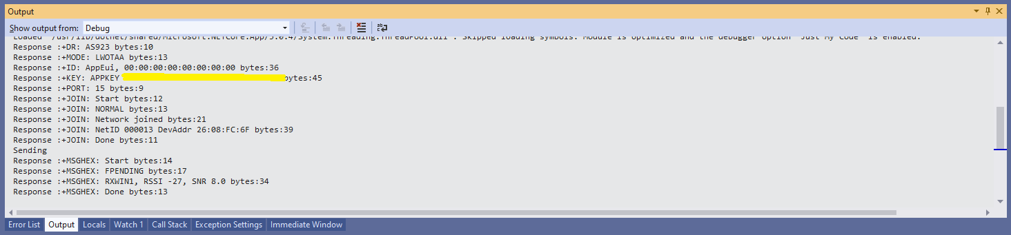
The code is not suitable for production but it confirmed my software and hardware configuration worked.
Visual Studio debugger output window showing network join and sensing a message
In the Visual Studio 2019 debug output I could see messages getting sent and then after a short delay they were visible in the TTN console.
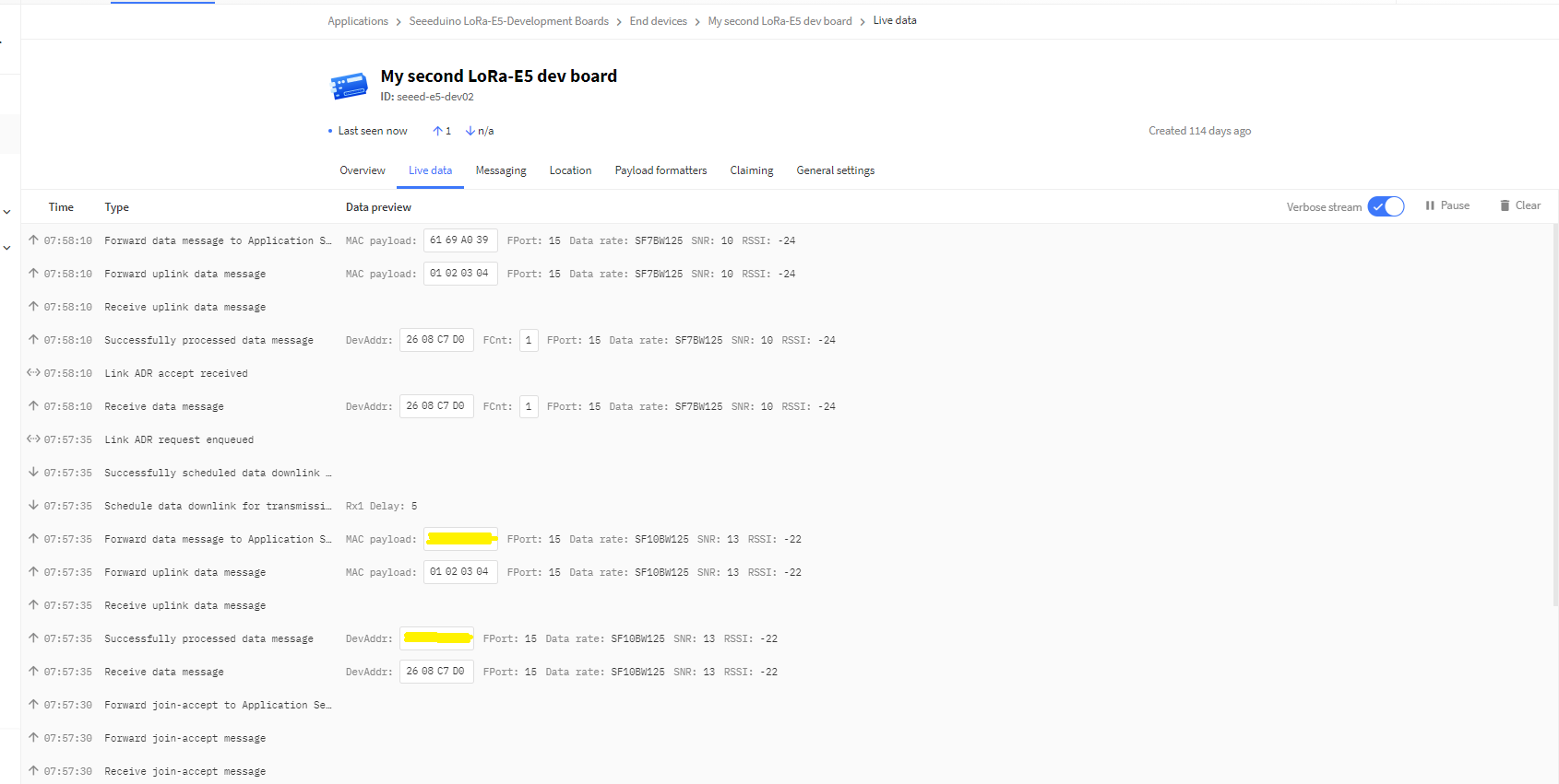
The Things Industries Live Data view showing network join and sensing a message
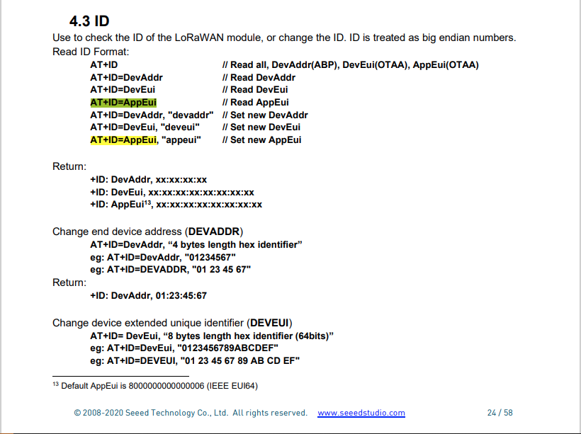
Most of the LoRaWAN modems I have worked with reply “OK” when a command is successful. The SeeedLoRa-E5 often returns the payload of the request in the response which makes the code a little bit more complex.
AppEui command structure in AT Command documentation
For example the AppEui can be passed in as “00:00:00:00:00:00:00:00” or “0000000000000000” but in the response the format is always “00:00:00:00:00:00:00:00”
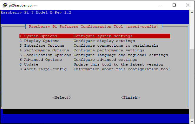
RaspberyPI OS Software Configuration tool mains screen
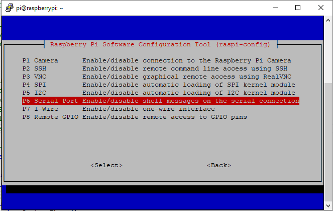
RaspberryPI OS IO Serial Port configuration
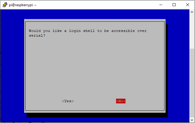
Raspberry PI OS disabling remote serial login shell
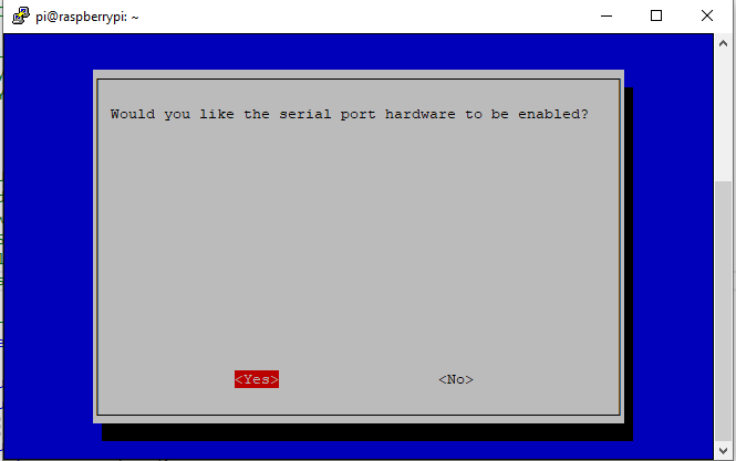
RaspberryPI OS enabling serial port access
Once serial port access was enabled I could enumerate them with SerialPort.GetPortNames() which is in the System.IO.PortsNuGet package. The code has compile time options for synchronous and asynchronous operation.
//---------------------------------------------------------------------------------
// Copyright (c) September 2021, devMobile Software
//
// Licensed under the Apache License, Version 2.0 (the "License");
// you may not use this file except in compliance with the License.
// You may obtain a copy of the License at
//
//     http://www.apache.org/licenses/LICENSE-2.0
//
// Unless required by applicable law or agreed to in writing, software
// distributed under the License is distributed on an "AS IS" BASIS,
// WITHOUT WARRANTIES OR CONDITIONS OF ANY KIND, either express or implied.
// See the License for the specific language governing permissions and
// limitations under the License.
//
//---------------------------------------------------------------------------------
namespace devMobile.IoT.NetCore.SeeedLoRaE5.ShieldSerial
{
	using System;
	using System.Diagnostics;
	using System.IO.Ports;
	using System.Threading;

	public class Program
	{
		private const string SerialPortId = "/dev/ttyS0";

		public static void Main()
		{
			SerialPort serialPort;

			Debug.WriteLine("devMobile.IoT.NetCore.SeeedLoRaE5.ShieldSerial starting");

			Debug.WriteLine(String.Join(",", SerialPort.GetPortNames()));

			try
			{
				serialPort = new SerialPort(SerialPortId);

				// set parameters
				serialPort.BaudRate = 9600;
				serialPort.Parity = Parity.None;
				serialPort.DataBits = 8;
				serialPort.StopBits = StopBits.One;
				serialPort.Handshake = Handshake.None;

				serialPort.ReadTimeout = 1000;

				serialPort.NewLine = "\r\n";

				serialPort.Open();

#if SERIAL_ASYNC_READ
				serialPort.DataReceived += SerialDevice_DataReceived;
#endif

				while (true)
				{
					serialPort.WriteLine("AT+VER");

#if SERIAL_SYNC_READ
					string response = serialPort.ReadLine();

					Debug.WriteLine($"RX:{response.Trim()} bytes:{response.Length}");
#endif

					Thread.Sleep(20000);
				}
			}
			catch (Exception ex)
			{
				Debug.WriteLine(ex.Message);
			}
		}

#if SERIAL_ASYNC_READ
		private static void SerialDevice_DataReceived(object sender, SerialDataReceivedEventArgs e)
		{
			SerialPort serialPort = (SerialPort)sender;

			switch (e.EventType)
			{
				case SerialData.Chars:
					string response = serialPort.ReadExisting();

					Debug.WriteLine($"RX:{response.Trim()} bytes:{response.Length}");
					break;

				case SerialData.Eof:
					Debug.WriteLine("RX :EoF");
					break;
				default:
					Debug.Assert(false, $"e.EventType {e.EventType} unknown");
					break;
			}
		}
#endif
	}
}
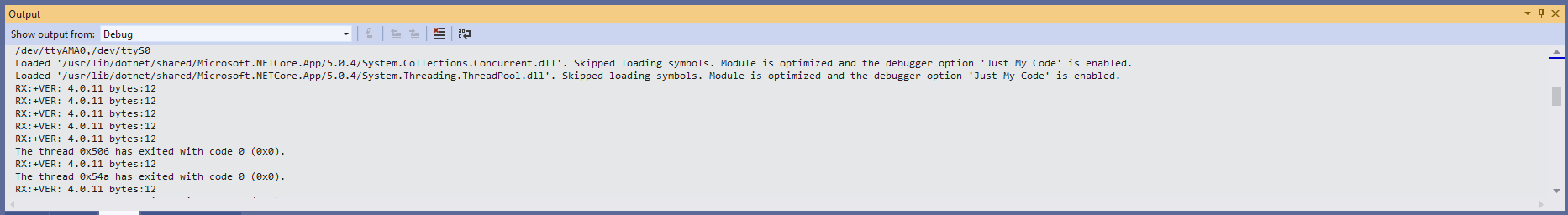
The synchronous version of the test client requests the Seeeduino LoRa-E5 version information with the AT+VER command.
Synchronously reading characters from the Seeeduino LoRa-E5
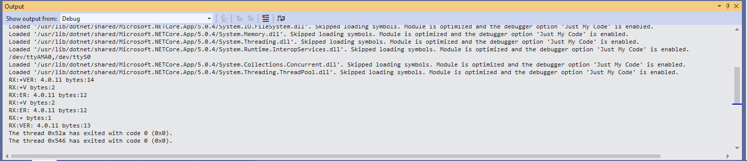
The asynchronous version of the application displays character(s) as they arrive so a response can be split across multiple SerialDataReceived events.
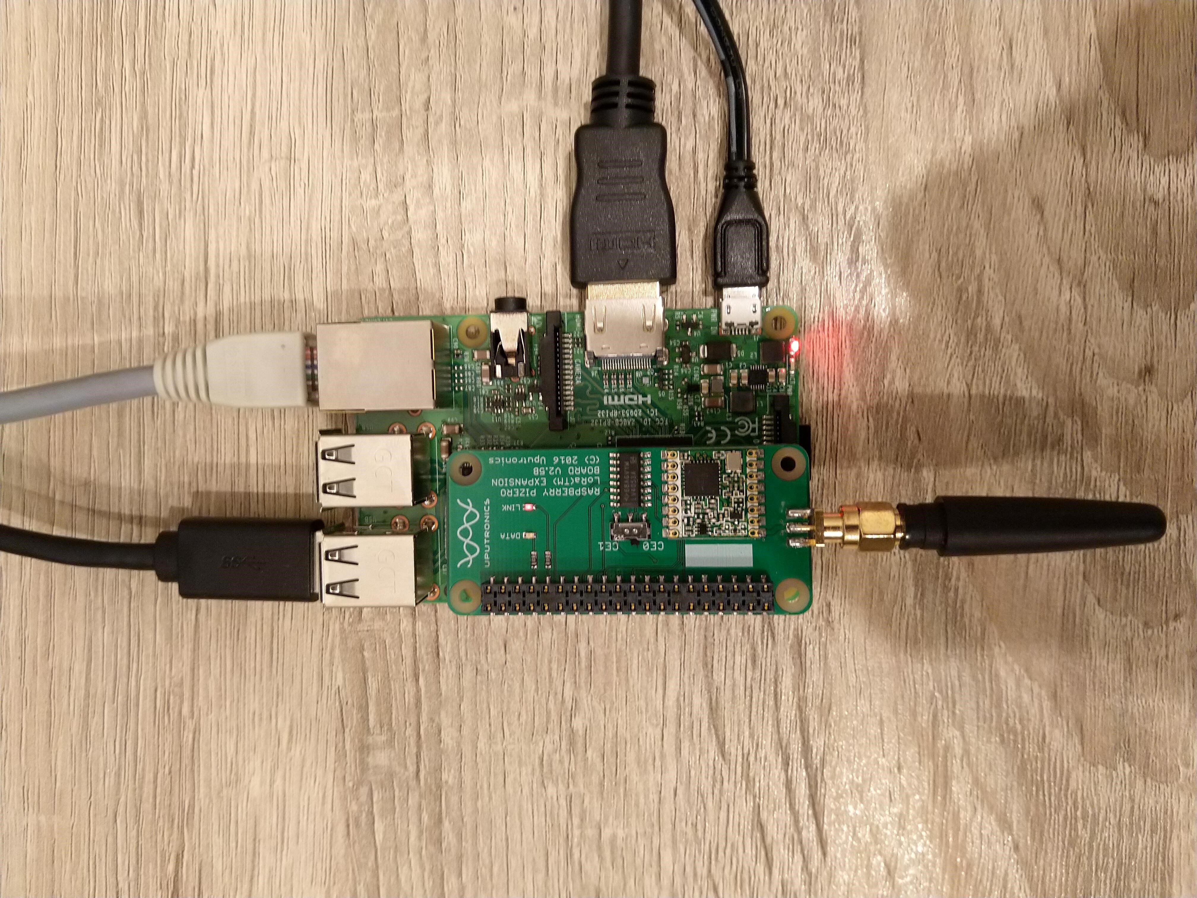
Uputronics Raspberry PIZero LoRa Expansion board on a Raspberry 3 device
The Uputronics pHat has a pair of Light Emitting Diodes(LEDs) so I adapted some code from a previous post to flash these to confirm the card was working.
static void UputronicsLeds()
{
	const int RedLedPinNumber = 6;
	const int GreenLedPinNumber = 13;

	GpioController controller = new GpioController(PinNumberingScheme.Logical);

	controller.OpenPin(RedLedPinNumber, PinMode.Output);
	controller.OpenPin(GreenLedPinNumber, PinMode.Output);

	while (true)
	{
		if (controller.Read(RedLedPinNumber) == PinValue.Low)
		{
			controller.Write(RedLedPinNumber, PinValue.High);
			controller.Write(GreenLedPinNumber, PinValue.Low);
		}
		else
		{
			controller.Write(RedLedPinNumber, PinValue.Low);
			controller.Write(GreenLedPinNumber, PinValue.High);
		}

		Thread.Sleep(1000);
	}
}
The first Uputronics pHat version using spiDevice.TransferFullDuplex didn’t work. I tried allocating memory for the buffers with new and stackalloc which didn’t seem to make any difference in my trivial example. I tried different Chip Select(CS) pin options, frequencies and modes (the mode used is based on the timings specified in the SX127X datasheet).
static void TransferFullDuplex()
{
	//byte[] writeBuffer = new byte[1]; // Memory allocation didn't seem to make any difference
    //byte[] readBuffer = new byte[1];
	Span<byte> writeBuffer = stackalloc byte[1];
	Span<byte> readBuffer = stackalloc byte[1];

	//var settings = new SpiConnectionSettings(0)
	var settings = new SpiConnectionSettings(0, 0)
	//var settings = new SpiConnectionSettings(0, 1)
	{
		ClockFrequency = 5000000,
		//ClockFrequency = 500000, // Frequency didn't seem to make any difference
		Mode = SpiMode.Mode0,   // From SemTech docs pg 80 CPOL=0, CPHA=0
	};

	SpiDevice spiDevice = SpiDevice.Create(settings);

	Thread.Sleep(500);

	while (true)
	{
		try
		{
			for (byte registerIndex = 0; registerIndex <= 0x42; registerIndex++)
			{
				writeBuffer[0] = registerIndex;
				spiDevice.TransferFullDuplex(writeBuffer, readBuffer);
				//Debug.WriteLine("Register 0x{0:x2} - Value 0X{1:x2} - Bits {2}", writeBuffer[0], readBuffer[0], Convert.ToString(readBuffer[0], 2).PadLeft(8, '0')); // Debug output stopped after roughly 3 times round for loop often debugger would barf as well
				Console.WriteLine("Register 0x{0:x2} - Value 0X{1:x2} - Bits {2}", writeBuffer[0], readBuffer[0], Convert.ToString(readBuffer[0], 2).PadLeft(8, '0'));

				// Would be nice if SpiDevice has a TransferSequential
				/*
				writeBuffer[0] = registerIndex;
				spiDevice.TransferSequential(writeBuffer, readBuffer);
				Console.WriteLine("Register 0x{0:x2} - Value 0X{1:x2} - Bits {2}", writeBuffer[0], readBuffer[0], Convert.ToString(readBuffer[0], 2).PadLeft(8, '0'));
				*/
			}

			Console.WriteLine("");
			Thread.Sleep(5000);
		}
		catch (Exception ex)
		{
			Console.WriteLine(ex.Message);
		}
	}
}
static void ReadWriteChipSelectStandard()
{
	var settings = new SpiConnectionSettings(0) // Doesn't work
	//	var settings = new SpiConnectionSettings(0, 0) // Doesn't work
	//var settings = new SpiConnectionSettings(0, 1) // Doesn't Work
	{
		ClockFrequency = 5000000,
		ChipSelectLineActiveState = PinValue.Low,
		Mode = SpiMode.Mode0,   // From SemTech docs pg 80 CPOL=0, CPHA=0
	};

	SpiDevice spiDevice = SpiDevice.Create(settings);

	Thread.Sleep(500);

	while (true)
	{
		try
		{
			for (byte registerIndex = 0; registerIndex <= 0x42; registerIndex++)
			{
				spiDevice.WriteByte(registerIndex);
				//Thread.Sleep(5); These made no difference
				//Thread.Sleep(10);
				//Thread.Sleep(20);
				//Thread.Sleep(40);
				byte registerValue = spiDevice.ReadByte();

				Console.WriteLine("Register 0x{0:x2} - Value 0X{1:x2} - Bits {2}", registerIndex, registerValue, Convert.ToString(registerValue, 2).PadLeft(8, '0'));
			}
			Console.WriteLine("");

			Thread.Sleep(5000);
		}
		catch (Exception ex)
		{
			Console.WriteLine(ex.Message);
		}
	}
}
The third Uputronics pHat version using spiDevice.ReadByte() and spiDevice.WriteByte() with DIY Chip Select(CS) worked. In previous SPI device libraries I have found that “managing” the CS line in code can be easier to get working The MicroFramework also has more connectionSettings options for better control of CS line timings which reduces the need for DIY.
static void ReadWriteChipSelectDiy()
{
	const int CSPinNumber = 8; // CS0
	//const int CSPinNumber = 7; // CS1

	// DIY CS0 implented with GPIO pin application controls
	GpioController controller = new GpioController(PinNumberingScheme.Logical);

	controller.OpenPin(CSPinNumber, PinMode.Output);
	//controller.Write(CSPinNumber, PinValue.High);

	//var settings = new SpiConnectionSettings(0) // Doesn't work
	var settings = new SpiConnectionSettings(0, 1) // Works, have to point at unused CS1, this could be a problem is other device on CS1
	//var settings = new SpiConnectionSettings(0, 0) // Works, have to point at unused CS0, this could be a problem is other device on CS0
	{
		ClockFrequency = 5000000,
		Mode = SpiMode.Mode0,   // From SemTech docs pg 80 CPOL=0, CPHA=0
	};

	SpiDevice spiDevice = SpiDevice.Create(settings);

	Thread.Sleep(500);

	while (true)
	{
		try
		{
			for (byte registerIndex = 0; registerIndex <= 0x42; registerIndex++)
			{
				controller.Write(CSPinNumber, PinValue.Low);
				spiDevice.WriteByte(registerIndex);
				//Thread.Sleep(2); // This maybe necessary
				byte registerValue = spiDevice.ReadByte();
				controller.Write(CSPinNumber, PinValue.High);

				Console.WriteLine("Register 0x{0:x2} - Value 0X{1:x2} - Bits {2}", registerIndex, registerValue, Convert.ToString(registerValue, 2).PadLeft(8, '0'));
			}
			Console.WriteLine("");

			Thread.Sleep(5000);
		}
		catch (Exception ex)
		{
			Console.WriteLine(ex.Message);
		}
	}
}
The dotNet/IoT doesn’t support (July2021) the option to “exclusively” open a port so there could be issues with other applications assuming they control CS0/CS1.
Loaded '/usr/lib/dotnet/shared/Microsoft.NETCore.App/5.0.4/Microsoft.Win32.Primitives.dll'. Skipped loading symbols. Module is optimized and the debugger option 'Just My Code' is enabled.
Register 0x00 - Value 0X00 - Bits 00000000
Register 0x01 - Value 0X09 - Bits 00001001
Register 0x02 - Value 0X1a - Bits 00011010
Register 0x03 - Value 0X0b - Bits 00001011
Register 0x04 - Value 0X00 - Bits 00000000
Register 0x05 - Value 0X52 - Bits 01010010
Register 0x06 - Value 0X6c - Bits 01101100
Register 0x07 - Value 0X80 - Bits 10000000
Register 0x08 - Value 0X00 - Bits 00000000
Register 0x09 - Value 0X4f - Bits 01001111
Register 0x0a - Value 0X09 - Bits 00001001
Register 0x0b - Value 0X2b - Bits 00101011
Register 0x0c - Value 0X20 - Bits 00100000
Register 0x0d - Value 0X08 - Bits 00001000
Register 0x0e - Value 0X02 - Bits 00000010
Register 0x0f - Value 0X0a - Bits 00001010
Register 0x10 - Value 0Xff - Bits 11111111
Register 0x11 - Value 0X70 - Bits 01110000
Register 0x12 - Value 0X15 - Bits 00010101
Register 0x13 - Value 0X0b - Bits 00001011
Register 0x14 - Value 0X28 - Bits 00101000
Register 0x15 - Value 0X0c - Bits 00001100
Register 0x16 - Value 0X12 - Bits 00010010
Register 0x17 - Value 0X47 - Bits 01000111
Register 0x18 - Value 0X32 - Bits 00110010
Register 0x19 - Value 0X3e - Bits 00111110
Register 0x1a - Value 0X00 - Bits 00000000
Register 0x1b - Value 0X00 - Bits 00000000
Register 0x1c - Value 0X00 - Bits 00000000
Register 0x1d - Value 0X00 - Bits 00000000
Register 0x1e - Value 0X00 - Bits 00000000
Register 0x1f - Value 0X40 - Bits 01000000
Register 0x20 - Value 0X00 - Bits 00000000
Register 0x21 - Value 0X00 - Bits 00000000
Register 0x22 - Value 0X00 - Bits 00000000
Register 0x23 - Value 0X00 - Bits 00000000
Register 0x24 - Value 0X05 - Bits 00000101
Register 0x25 - Value 0X00 - Bits 00000000
Register 0x26 - Value 0X03 - Bits 00000011
Register 0x27 - Value 0X93 - Bits 10010011
Register 0x28 - Value 0X55 - Bits 01010101
Register 0x29 - Value 0X55 - Bits 01010101
Register 0x2a - Value 0X55 - Bits 01010101
Register 0x2b - Value 0X55 - Bits 01010101
Register 0x2c - Value 0X55 - Bits 01010101
Register 0x2d - Value 0X55 - Bits 01010101
Register 0x2e - Value 0X55 - Bits 01010101
Register 0x2f - Value 0X55 - Bits 01010101
Register 0x30 - Value 0X90 - Bits 10010000
Register 0x31 - Value 0X40 - Bits 01000000
Register 0x32 - Value 0X40 - Bits 01000000
Register 0x33 - Value 0X00 - Bits 00000000
Register 0x34 - Value 0X00 - Bits 00000000
Register 0x35 - Value 0X0f - Bits 00001111
Register 0x36 - Value 0X00 - Bits 00000000
Register 0x37 - Value 0X00 - Bits 00000000
Register 0x38 - Value 0X00 - Bits 00000000
Register 0x39 - Value 0Xf5 - Bits 11110101
Register 0x3a - Value 0X20 - Bits 00100000
Register 0x3b - Value 0X82 - Bits 10000010
Register 0x3c - Value 0Xf6 - Bits 11110110
Register 0x3d - Value 0X02 - Bits 00000010
Register 0x3e - Value 0X80 - Bits 10000000
Register 0x3f - Value 0X40 - Bits 01000000
Register 0x40 - Value 0X00 - Bits 00000000
Register 0x41 - Value 0X00 - Bits 00000000
Register 0x42 - Value 0X12 - Bits 00010010
The fourth Uputronics pHat version using spiDevice.TransferFullDuplex with read and write buffers two bytes long and the leading bye of the response ignored worked.
...
while (true)
{
	try
	{
		for (byte registerIndex = 0; registerIndex <= 0x42; registerIndex++)
		{
			// Doesn't work
			writeBuffer[0] = registerIndex;
			spiDevice.TransferFullDuplex(writeBuffer, readBuffer);
			Console.WriteLine("Register 0x{0:x2} - Value 0X{1:x2} - Bits {2}", registerIndex, readBuffer[0], Convert.ToString(readBuffer[0], 2).PadLeft(8, '0'));

			// Does work
			writeBuffer[0] = registerIndex;
			spiDevice.TransferFullDuplex(writeBuffer, readBuffer);
			Console.WriteLine("Register 0x{0:x2} - Value 0X{1:x2} - Bits {2}", registerIndex, readBuffer[1], Convert.ToString(readBuffer[1], 2).PadLeft(8, '0'));

			// Does work
			writeBuffer[1] = registerIndex;
			spiDevice.TransferFullDuplex(writeBuffer, readBuffer);
			Console.WriteLine("Register 0x{0:x2} - Value 0X{1:x2} - Bits {2}", registerIndex, readBuffer[1], Convert.ToString(readBuffer[1], 2).PadLeft(8, '0'));

			Console.WriteLine("");
		}

		Console.WriteLine("");
		Thread.Sleep(5000);
	}
	catch (Exception ex)
	{
		Console.WriteLine(ex.Message);
	}
}
Register 0x00 - Value 0X00 - Bits 00000000
Register 0x00 - Value 0X00 - Bits 00000000
Register 0x00 - Value 0X00 - Bits 00000000

...

Register 0x42 - Value 0X00 - Bits 00000000
Register 0x42 - Value 0X12 - Bits 00010010
Register 0x42 - Value 0X12 - Bits 00010010
M2M Single channel shield on Raspberry Pi 3 Device
The first M2M pHat version using SpiDevice.Read and SpiDevice.Write with a “custom” CS pin worked.
...
// Chip select with pin which isn't CS0 or CS1 needs M2M shield
static void ReadWriteDiyChipSelectNonStandard()
{
	const int CSPinNumber = 25;

	// DIY CS0 implented with GPIO pin application controls
	GpioController controller = new GpioController(PinNumberingScheme.Logical);

	controller.OpenPin(CSPinNumber, PinMode.Output);
	//controller.Write(CSPinNumber, PinValue.High);

	// Work, this could be a problem is other device on CS0/CS1
	var settings = new SpiConnectionSettings(0)
	//var settings = new SpiConnectionSettings(0, 0)
	//var settings = new SpiConnectionSettings(0, 1)
	{
		ClockFrequency = 5000000,
		Mode = SpiMode.Mode0,   // From SemTech docs pg 80 CPOL=0, CPHA=0
	};

	SpiDevice spiDevice = SpiDevice.Create(settings);

	Thread.Sleep(500);

	while (true)
	{
		try
		{
			for (byte registerIndex = 0; registerIndex <= 0x42; registerIndex++)
			{
				controller.Write(CSPinNumber, PinValue.Low);
				spiDevice.WriteByte(registerIndex);
				//Thread.Sleep(2); // This maybe necessary
				byte registerValue = spiDevice.ReadByte();
				controller.Write(CSPinNumber, PinValue.High);

				Console.WriteLine("Register 0x{0:x2} - Value 0X{1:x2} - Bits {2}", registerIndex, registerValue, Convert.ToString(registerValue, 2).PadLeft(8, '0'));
			}
			Console.WriteLine("");

			Thread.Sleep(5000);
		}
		catch (Exception ex)
		{
			Console.WriteLine(ex.Message);
		}
	}
}
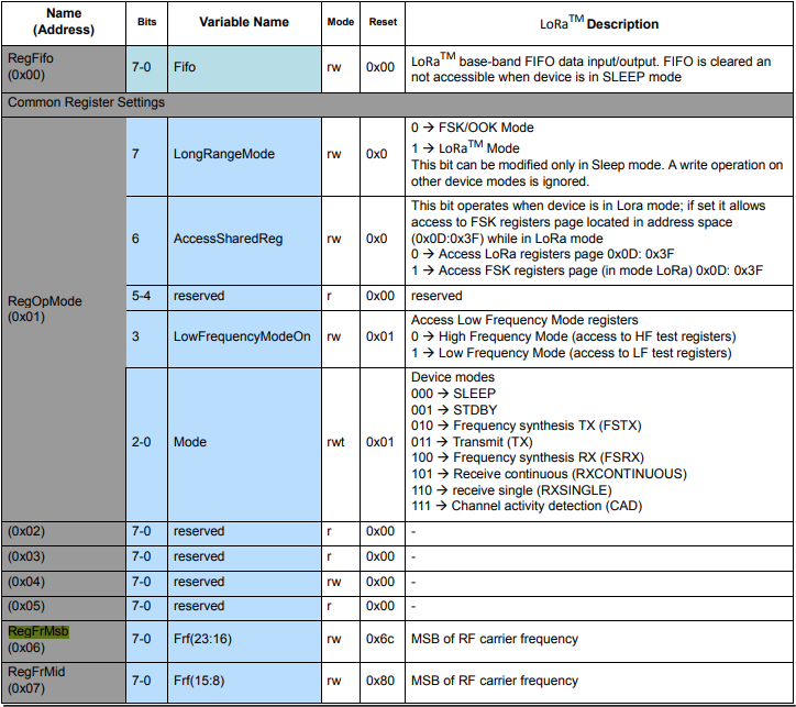
The next step was to read an array of bytes, using spiDevice.TransferFullDuplex. The SX127X transmit/receive frequency is specified in registers 0x06 RegFrMSB, 0x07 RegFrMid, and 0x08 RegFrLsb. The default frequency is 868MHz which is 0xE4, 0xC0, 0x00
static void TransferFullDuplexBufferBytesRead()
{
	const byte length = 3;
	byte[] writeBuffer = new byte[length + 1];
	byte[] readBuffer = new byte[length + 1];

	// Read the frequency which is 3 bytes RegFrMsb 0x6c, RegFrMid 0x80, RegFrLsb 0x00
	writeBuffer[0] = 0x06; //

	// Works, have to point at unused CS0/CS1, others could be a problem is another another SPI device is on on CS0/CS1
	//var settings = new SpiConnectionSettings(0)
	var settings = new SpiConnectionSettings(0, 0)
	//var settings = new SpiConnectionSettings(0, 1)
	{
		ClockFrequency = 5000000,
		Mode = SpiMode.Mode0,   // From SemTech docs pg 80 CPOL=0, CPHA=0
	};

	SpiDevice spiDevice = SpiDevice.Create(settings);

	spiDevice.TransferFullDuplex(writeBuffer, readBuffer);

	Console.WriteLine($"Register 0x06-0x{readBuffer[1]:x2} 0x07-0x{readBuffer[2]:x2} 0x08-0x{readBuffer[3]:x2}");
}
-------------------------------------------------------------------
You may only use the Microsoft .NET Core Debugger (vsdbg) with
Visual Studio Code, Visual Studio or Visual Studio for Mac software
to help you develop and test your applications.
-------------------------------------------------------------------
Loaded '/usr/lib/dotnet/shared/Microsoft.NETCore.App/5.0.4/System.Private.CoreLib.dll'. Skipped loading symbols. Module is optimized and the debugger option 'Just My Code' is enabled.
...
Loaded '/usr/lib/dotnet/shared/Microsoft.NETCore.App/5.0.4/Microsoft.Win32.Primitives.dll'. Skipped loading symbols. Module is optimized and the debugger option 'Just My Code' is enabled.
Register 0x06-0xe4 0x07-0xc0 0x08-0x00
The final step was write an array of bytes, using spiDevice.TransferFullDuplex to change the transmit/receive frequency to 915MHz. To write a value the first bit of the address byte must be set to 1 hence the 0x86 RegFrMsb address.
static void TransferFullDuplexBufferBytesWrite()
{
	const byte length = 3;
	byte[] writeBuffer = new byte[length + 1];
	byte[] readBuffer = new byte[length + 1];

	// Write the frequency which is 3 bytes RegFrMsb 0x6c, RegFrMid 0x80, RegFrLsb or with 0x00 the write mask
	writeBuffer[0] = 0x86 ;

	// Works, have to point at unused CS0/CS1, others could be a problem is another another SPI device is on on CS0/CS1
	//var settings = new SpiConnectionSettings(0)
	var settings = new SpiConnectionSettings(0, 0)
	//var settings = new SpiConnectionSettings(0, 1)
	{
		ClockFrequency = 5000000,
		Mode = SpiMode.Mode0,   // From SemTech docs pg 80 CPOL=0, CPHA=0
	};

	SpiDevice spiDevice = SpiDevice.Create(settings);

	// Set the frequency to 915MHz
	writeBuffer[1] = 0xE4;
	writeBuffer[2] = 0xC0;
	writeBuffer[3] = 0x00;

	spiDevice.TransferFullDuplex(writeBuffer, readBuffer);
}
-------------------------------------------------------------------
You may only use the Microsoft .NET Core Debugger (vsdbg) with
Visual Studio Code, Visual Studio or Visual Studio for Mac software
to help you develop and test your applications.
-------------------------------------------------------------------
Loaded '/usr/lib/dotnet/shared/Microsoft.NETCore.App/5.0.4/System.Private.CoreLib.dll'. Skipped loading symbols. Module is optimized and the debugger option 'Just My Code' is enabled.
...
Loaded '/usr/lib/dotnet/shared/Microsoft.NETCore.App/5.0.4/Microsoft.Win32.Primitives.dll'. Skipped loading symbols. Module is optimized and the debugger option 'Just My Code' is enabled.
Register 0x06-0x6c 0x07-0x80 0x08-0x00
Register 0x06-0xe4 0x07-0xc0 0x08-0x00
The program 'dotnet' has exited with code 0 (0x0).
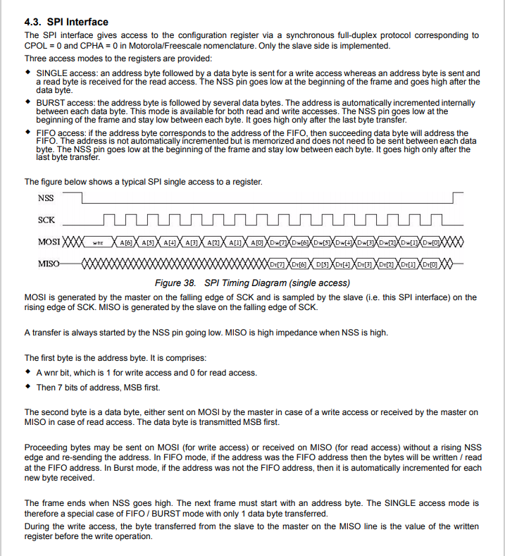
Summary
This exceptionally long post was to highlight that with SPI it’s all about timing, first read the datasheet, then build code to validate your understanding.
SX127X SPI interface timing diagram
Some platforms have native TransferSequential implementations but the dotNet/IoT library only has TransferFullDuplex. SPI hardware is always full duplex, if “sequential” is available the implementation will write the provided bytes and then follow them with zeros to read the requested bytes.
-------------------------------------------------------------------
You may only use the Microsoft .NET Core Debugger (vsdbg) with
Visual Studio Code, Visual Studio or Visual Studio for Mac software
to help you develop and test your applications.
-------------------------------------------------------------------
...
Loaded '/usr/lib/dotnet/shared/Microsoft.NETCore.App/5.0.4/Microsoft.Win32.Primitives.dll'. Skipped loading symbols. Module is optimized and the debugger option 'Just My Code' is enabled.
Main thread:1
Doing stuff
Doing stuff
Doing stuff
Doing stuff
Doing stuff
Interrupt Thread:6Doing stuff
Doing stuff
Doing stuff
Interrupt Thread:6Doing stuff
Doing stuff
Interrupt Thread:6Doing stuff
Doing stuff
Doing stuff
Doing stuff
Doing stuff
Doing stuff
The program 'dotnet' has exited with code 0 (0x0).
The ManagedThreadId for the main loop(1) was different to the callback(6) which needs some further investigation.
using System;
using System.Diagnostics;
using System.Threading;

namespace devMobile.NetCore.ConsoleApp
{
	class Program
	{
		static void Main(string[] args)
		{
			while (true)
			{
				Console.WriteLine($"{DateTime.UtcNow:HH:mm:ss} Hello World!");

				Thread.Sleep(1000);
			}
		}
	}
}
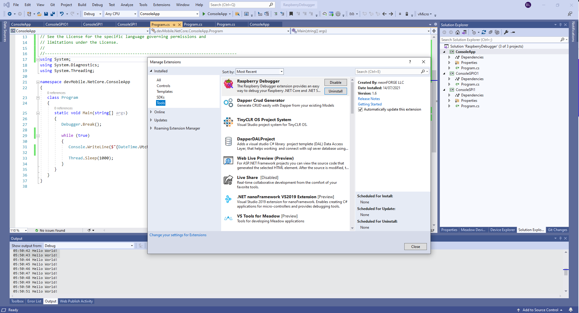
The RaspberryDebugger is really simple to install, and “frictionless” to use. The developers have put a lot of effort into making it easy to deploy and debug a .Net Core application running on a Raspberry PI with Visual Studio. All I had to do was search for, then download and install their Visual Studio Extension(VSIX).
Visual Studio Manage Extensions search
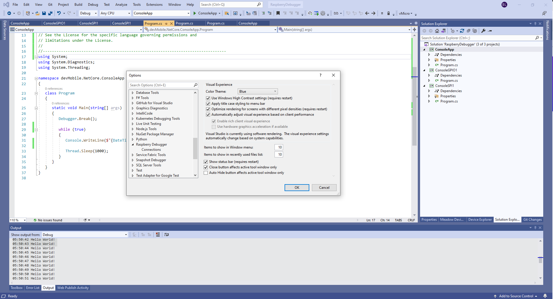
Then configure the connection information for the devices I wanted to use.
Visual Studio Options menu for RaspberryDebugger
On my main development system I was using multiple Raspberry PI devices so it was great to be able to pre-configure several devices.
RaspberryDebugger device(s) configuration)
I had connected to each device with PuTTY to check that connectivity was sorted.
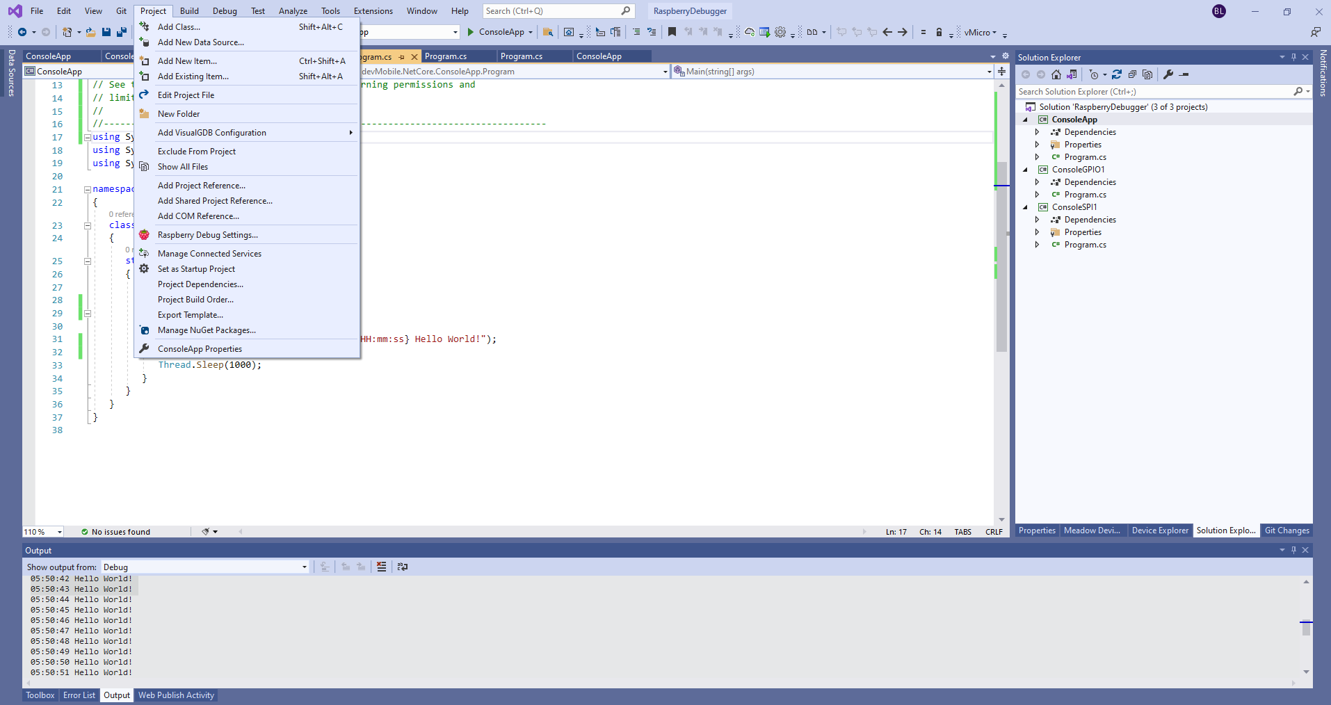
After typing in my “Hello world” application I had to select the device I wanted to use
Project menu RaspberryDebugger option
RaspberryDebugger device selection
Then I pressed F5 and it worked! It’s very unusual for things to work first time so I was stunned. The application was “automagically” downloaded and run in the debugger on the device.
-------------------------------------------------------------------
You may only use the Microsoft .NET Core Debugger (vsdbg) with
Visual Studio Code, Visual Studio or Visual Studio for Mac software
to help you develop and test your applications.
-------------------------------------------------------------------
Loaded '/usr/lib/dotnet/shared/Microsoft.NETCore.App/5.0.4/System.Private.CoreLib.dll'. Skipped loading symbols. Module is optimized and the debugger option 'Just My Code' is enabled.
Loaded '/home/pi/vsdbg/ConsoleApp/ConsoleApp.dll'. Symbols loaded.
Loaded '/usr/lib/dotnet/shared/Microsoft.NETCore.App/5.0.4/System.Runtime.dll'. Skipped loading symbols. Module is optimized and the debugger option 'Just My Code' is enabled.
Loaded '/usr/lib/dotnet/shared/Microsoft.NETCore.App/5.0.4/System.Console.dll'. Skipped loading symbols. Module is optimized and the debugger option 'Just My Code' is enabled.
Loaded '/usr/lib/dotnet/shared/Microsoft.NETCore.App/5.0.4/System.Threading.Thread.dll'. Skipped loading symbols. Module is optimized and the debugger option 'Just My Code' is enabled.
Loaded '/usr/lib/dotnet/shared/Microsoft.NETCore.App/5.0.4/System.Threading.dll'. Skipped loading symbols. Module is optimized and the debugger option 'Just My Code' is enabled.
Loaded '/usr/lib/dotnet/shared/Microsoft.NETCore.App/5.0.4/System.Text.Encoding.Extensions.dll'. Skipped loading symbols. Module is optimized and the debugger option 'Just My Code' is enabled.
Loaded '/usr/lib/dotnet/shared/Microsoft.NETCore.App/5.0.4/Microsoft.Win32.Primitives.dll'. Skipped loading symbols. Module is optimized and the debugger option 'Just My Code' is enabled.
05:50:37 Hello World!
05:50:39 Hello World!
05:50:40 Hello World!
05:50:41 Hello World!
05:50:42 Hello World!
05:50:43 Hello World!
...
The next step was to figure out how to configure a Pulse Width Modulation (PWM) output and an Analog Input so I could adjust the duty cycle and control the brightness of a Light Emitting Diode(LED).
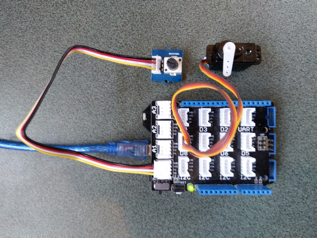
Netduino 3 ADC & PWN test rig
My test rig uses (prices as at Aug 2020) the following parts
 public class Program
   {
      public static void Main()
      {
         Debug.WriteLine("devMobile.Longboard.AdcTest starting");
         Debug.WriteLine(AdcController.GetDeviceSelector());

         try
         {
            AdcController adc = AdcController.GetDefault();
            AdcChannel adcChannel = adc.OpenChannel(0);

            while (true)
            {
               double value = adcChannel.ReadRatio();

               Debug.WriteLine($"Value: {value:F2}");

               Thread.Sleep(100);
            }
         }
         catch (Exception ex)
         {
            Debug.WriteLine(ex.Message);
         }
      }
   }
The nanoFramework code polls for the rotary angle sensor for its position value every 100mSec.
The setup to use for the Analog to Digital Convertor(ADC) port was determined by looking at the board.h and target_windows_devices_adc_config.cpp file.
//
// Copyright (c) 2018 The nanoFramework project contributors
// See LICENSE file in the project root for full license information.
//

#include <win_dev_adc_native_target.h>

const NF_PAL_ADC_PORT_PIN_CHANNEL AdcPortPinConfig[] = {

    // ADC1
    {1, GPIOC, 0, ADC_CHANNEL_IN10},
    {1, GPIOC, 1, ADC_CHANNEL_IN11},

    // ADC2
    {2, GPIOC, 2, ADC_CHANNEL_IN14},
    {2, GPIOC, 3, ADC_CHANNEL_IN15},

    // ADC3
    {3, GPIOC, 4, ADC_CHANNEL_IN12},
    {3, GPIOC, 5, ADC_CHANNEL_IN13},

    // these are the internal sources, available only at ADC1
    {1, NULL, 0, ADC_CHANNEL_SENSOR},
    {1, NULL, 0, ADC_CHANNEL_VREFINT},
    {1, NULL, 0, ADC_CHANNEL_VBAT},
};

const int AdcChannelCount = ARRAYSIZE(AdcPortPinConfig);
The call to AdcController.GetDeviceSelector() only returned one controller
The thread '<No Name>' (0x2) has exited with code 0 (0x0).
devMobile.Longboard.AdcTest starting
ADC1
After some experimentation it appears that only A0 & A1 work on a Netduino. (Aug 2020).
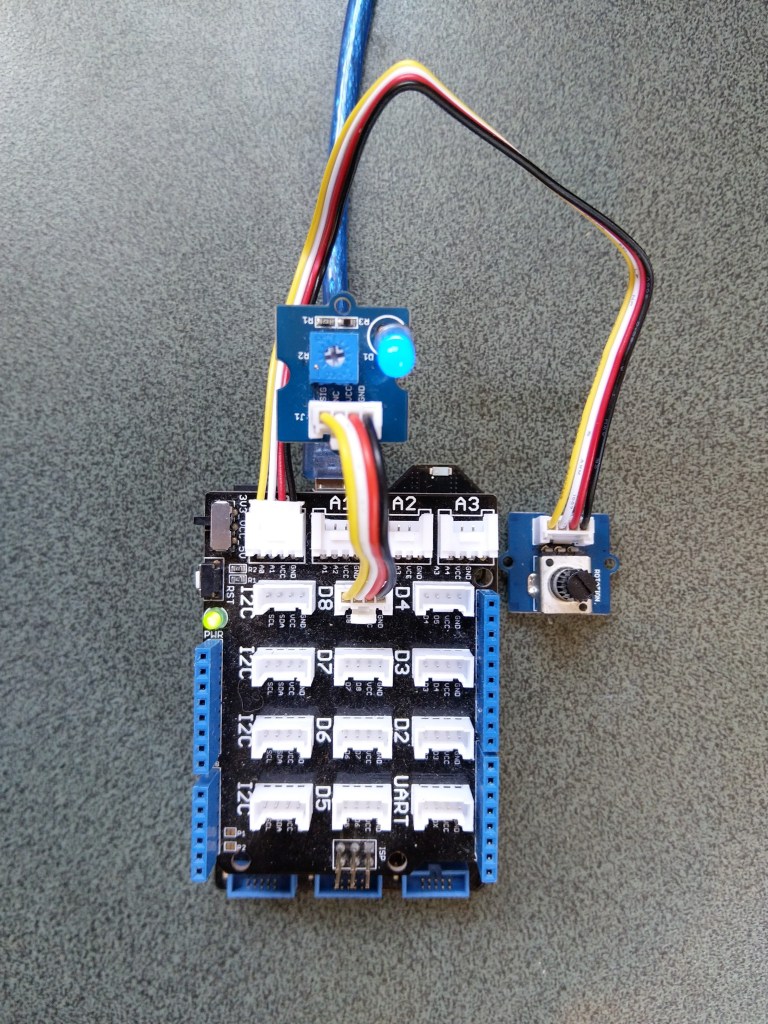
My PWM test harness
public class Program
{
   public static void Main()
   {
      Debug.WriteLine("devMobile.Longboard.PwmTest starting");
      Debug.WriteLine(PwmController.GetDeviceSelector());

      try
      {
         PwmController pwm = PwmController.FromId("TIM5");
         AdcController adc = AdcController.GetDefault();
         AdcChannel adcChannel = adc.OpenChannel(0);

         PwmPin pwmPin = pwm.OpenPin(PinNumber('A', 0));
         pwmPin.Controller.SetDesiredFrequency(1000);
         pwmPin.Start();

         while (true)
         {
            double value = adcChannel.ReadRatio();

            Debug.WriteLine(value.ToString("F2"));

            pwmPin.SetActiveDutyCyclePercentage(value);

            Thread.Sleep(100);
         }
      }
      catch (Exception ex)
      {
         Debug.WriteLine(ex.Message);
      }
   }

   private static int PinNumber(char port, byte pin)
   {
      if (port < 'A' || port > 'J')
         throw new ArgumentException();
      return ((port - 'A') * 16) + pin;
   }
}
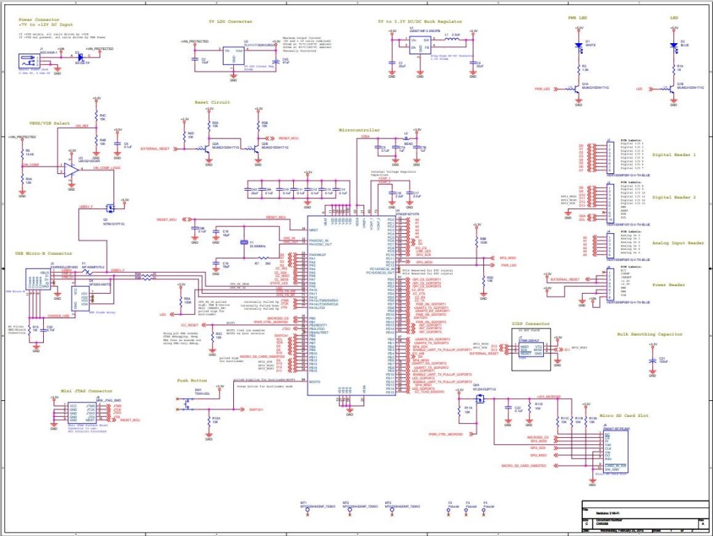
I had to refer to the Netduino schematic to figure out pin mapping
With my test rig (with easy access to D0 thru D8) I found that only D2,D3,D7 and D8 work as PWM outputs.
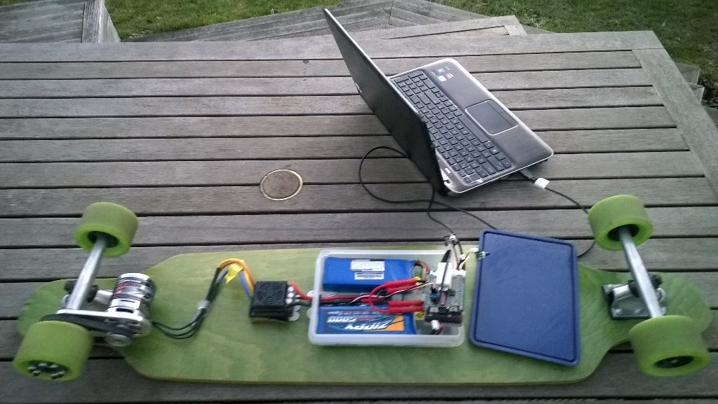
Roughly four years ago I build myself an electric longboard as summer transport. It initially had a controller built with a devDuino V2.2 which after a while I “upgraded” to a GHI Electronics.NET Microframework device.
Configuring the original netMF based longboard
Now that GHI Electronics no longer supports the FEZ Panda III I figured upgrading to a device that runs the nanoFramework would be a good compromise.
My changes were mainly related to the Inter Integrated Circuit(I2C) configuration and the reading+writing of registers.
/// <summary>
/// Initialises a new Wii Nunchuk
/// </summary>
/// <param name="busId">The unique identifier of the I²C to use.</param>
/// <param name="slaveAddress">The I²C address</param>
/// <param name="busSpeed">The bus speed, an enumeration that defaults to StandardMode</param>
/// <param name="sharingMode">The sharing mode, an enumeration that defaults to Shared.</param>
public WiiNunchuk(string busId, ushort slaveAddress = 0x52, I2cBusSpeed busSpeed = I2cBusSpeed.StandardMode, I2cSharingMode sharingMode = I2cSharingMode.Shared)
   {
      I2cTransferResult result;

      // This initialisation routine seems to work. I got it at http://wiibrew.org/wiki/Wiimote/Extension_Controllers#The_New_Way
      Device = I2cDevice.FromId(busId, new I2cConnectionSettings(slaveAddress)
      {
         BusSpeed = busSpeed,
         SharingMode = sharingMode,
      });

      result = Device.WritePartial(new byte[] { 0xf0, 0x55 });
      if (result.Status != I2cTransferStatus.FullTransfer)
      {
         throw new ApplicationException("Something went wrong reading the Nunchuk. Did you use proper pull-up resistors?");
      }

      result = Device.WritePartial(new byte[] { 0xfb, 0x00 });
      if (result.Status != I2cTransferStatus.FullTransfer)
      {
         throw new ApplicationException("Something went wrong reading the Nunchuk. Did you use proper pull-up resistors?");
      }

      this.Device.Write(new byte[] { 0xf0, 0x55 });
      this.Device.Write(new byte[] { 0xfb, 0x00 });
   }

   /// <summary>
   /// Reads all data from the nunchuk
   /// </summary>
   public void Read()
   {
      byte[] WaitWriteBuffer = { 0 };
      I2cTransferResult result;

      result = Device.WritePartial(WaitWriteBuffer);
      if (result.Status != I2cTransferStatus.FullTransfer)
      {
         throw new ApplicationException("Something went wrong reading the Nunchuk. Did you use proper pull-up resistors?");
      }

      byte[] ReadBuffer = new byte[6];
      result = Device.ReadPartial(ReadBuffer);
      if (result.Status != I2cTransferStatus.FullTransfer)
      {
         throw new ApplicationException("Something went wrong reading the Nunchuk. Did you use proper pull-up resistors?");
      }

      // Parses data according to http://wiibrew.org/wiki/Wiimote/Extension_Controllers/Nunchuck#Data_Format

      // Analog stick
      this.AnalogStickX = ReadBuffer[0];
      this.AnalogStickY = ReadBuffer[1];

      // Accelerometer
      ushort AX = (ushort)(ReadBuffer[2] << 2);
      ushort AY = (ushort)(ReadBuffer[3] << 2);
      ushort AZ = (ushort)(ReadBuffer[4] << 2);
      AZ += (ushort)((ReadBuffer[5] & 0xc0) >> 6); // 0xc0 = 11000000
      AY += (ushort)((ReadBuffer[5] & 0x30) >> 4); // 0x30 = 00110000
      AX += (ushort)((ReadBuffer[5] & 0x0c) >> 2); // 0x0c = 00001100
      this.AcceleroMeterX = AX;
      this.AcceleroMeterY = AY;
      this.AcceleroMeterZ = AZ;

      // Buttons
      ButtonC = (ReadBuffer[5] & 0x02) != 0x02;    // 0x02 = 00000010
      ButtonZ = (ReadBuffer[5] & 0x01) != 0x01;    // 0x01 = 00000001
}
The nanoFramework code polls for the joystick position and accelerometer values every 100mSec
public class Program
{
   public static void Main()
   {
      Debug.WriteLine("devMobile.Longboard.WiiNunchuckTest starting");
      Debug.WriteLine(I2cDevice.GetDeviceSelector());

      try
      {
         WiiNunchuk nunchuk = new WiiNunchuk("I2C1");

         while (true)
         {
            nunchuk.Read();

            Debug.WriteLine($"JoyX: {nunchuk.AnalogStickX} JoyY:{nunchuk.AnalogStickY} AX:{nunchuk.AcceleroMeterX} AY:{nunchuk.AcceleroMeterY} AZ:{nunchuk.AcceleroMeterZ} BtnC:{nunchuk.ButtonC} BtnZ:{nunchuk.ButtonZ}");

            Thread.Sleep(100);
         }
      }
      catch (Exception ex)
      {
         Debug.WriteLine(ex.Message);
      }
   }
}
The setup to use for the I2C port was determined by looking at the board.h and target_windows_devices_I2C_config.cpp file
//
// Copyright (c) 2018 The nanoFramework project contributors
// See LICENSE file in the project root for full license information.
//

#include <win_dev_i2c_native_target.h>

//////////
// I2C1 //
//////////

// pin configuration for I2C1
// port for SCL pin is: GPIOB
// port for SDA pin is: GPIOB
// SCL pin: is GPIOB_6
// SDA pin: is GPIOB_7
// GPIO alternate pin function is 4 (see alternate function mapping table in device datasheet)
I2C_CONFIG_PINS(1, GPIOB, GPIOB, 6, 7, 4)
Then checking this against the Netduino 3 Wifi schematic.
After some experimentation with how to detect if an I2C read or write had failed the debugging console output began displaying reasonable value