.NET Core 5 SX127X library Arduino Duplex

The arduino-LoRa library LoRaDuplex sample is the basis for the last in this series of posts. The LoRaDuplex sample implements a basic protocol for addressed messages. The message payload starts with the destination address(byte), source address(byte), message counter(byte), payload length(byte), and then the payload(array of bytes).

LoRaDuplex

The sample code has configuration settings for the local address and destination (address).

#include <SPI.h>              // include libraries
#include <LoRa.h>

const int csPin = 10;          // LoRa radio chip select
const int resetPin = 9;       // LoRa radio reset
const int irqPin = 2;         // change for your board; must be a hardware interrupt pin

String outgoing;              // outgoing message

byte msgCount = 0;            // count of outgoing messages
byte localAddress = 0xAA;     // address of this device
byte destination = 0x0;      // destination to send to
long lastSendTime = 0;        // last send time
int interval = 2000;          // interval between sends

void setup() {
  Serial.begin(9600);                   // initialize serial
  while (!Serial);

  Serial.println("LoRa Duplex");

  // override the default CS, reset, and IRQ pins (optional)
  LoRa.setPins(csPin, resetPin, irqPin);// set CS, reset, IRQ pin

  if (!LoRa.begin(915E6)) {             // initialize ratio at 915 MHz
    Serial.println("LoRa init failed. Check your connections.");
    while (true);                       // if failed, do nothing
  }

  LoRa.enableCrc();

  Serial.println("LoRa init succeeded.");
}

void loop() {
  if (millis() - lastSendTime > interval) {
    String message = "HeLoRa World!";   // send a message
    sendMessage(message);
    Serial.println("Sending " + message);
    lastSendTime = millis();            // timestamp the message
    interval = random(2000) + 29000;    // 2-3 seconds
  }

  // parse for a packet, and call onReceive with the result:
  onReceive(LoRa.parsePacket());
}

void sendMessage(String outgoing) {
  LoRa.beginPacket();                   // start packet
  LoRa.write(destination);              // add destination address
  LoRa.write(localAddress);             // add sender address
  LoRa.write(msgCount);                 // add message ID
  LoRa.write(outgoing.length());        // add payload length
  LoRa.print(outgoing);                 // add payload
  LoRa.endPacket();                     // finish packet and send it
  msgCount++;                           // increment message ID
}

void onReceive(int packetSize) {
  if (packetSize == 0) return;          // if there's no packet, return

  // read packet header bytes:
  int recipient = LoRa.read();          // recipient address
  byte sender = LoRa.read();            // sender address
  byte incomingMsgId = LoRa.read();     // incoming msg ID
  byte incomingLength = LoRa.read();    // incoming msg length

  String incoming = "";

  while (LoRa.available()) {
    incoming += (char)LoRa.read();
  }

  if (incomingLength != incoming.length()) {   // check length for error
    Serial.println("error: message length does not match length");
    return;                             // skip rest of function
  }

  // if the recipient isn't this device or broadcast,
  if (recipient != localAddress && recipient != 0xFF) {
    Serial.println("This message is not for me.");
    return;                             // skip rest of function
  }

  // if message is for this device, or broadcast, print details:
  Serial.println("Received from: 0x" + String(sender, HEX));
  Serial.println("Sent to: 0x" + String(recipient, HEX));
  Serial.println("Message ID: " + String(incomingMsgId));
  Serial.println("Message length: " + String(incomingLength));
  Serial.println("Message: " + incoming);
  Serial.println("RSSI: " + String(LoRa.packetRssi()));
  Serial.println("Snr: " + String(LoRa.packetSnr()));
  Serial.println();
}
Arduino Monitor displaying information about the messages sent and received by the Duplex sample

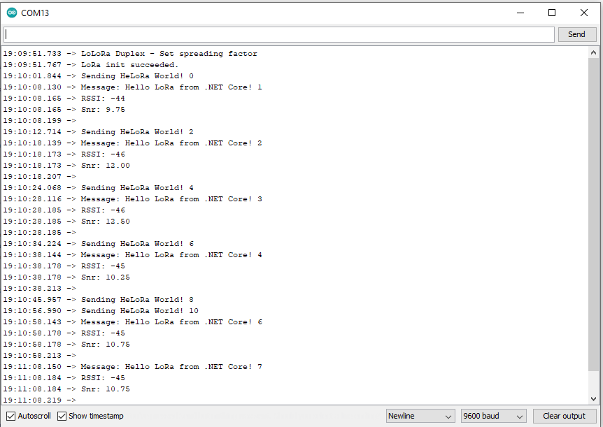
In the Visual Studio output window I could see the SX127XLoRaDeviceClient sending and receiving messages

Loaded '/usr/lib/dotnet/shared/Microsoft.NETCore.App/5.0.4/Microsoft.Win32.Primitives.dll'. Skipped loading symbols. Module is optimized and the debugger option 'Just My Code' is enabled.
17:26:10-TX to 0xAA from 0x00 count 1 length 28 "Hello LoRa from .NET Core! 1"
17:26:10-TX Done
17:26:20-TX to 0xAA from 0x00 count 2 length 28 "Hello LoRa from .NET Core! 2"
17:26:20-TX Done
17:26:30-TX to 0xAA from 0x00 count 3 length 28 "Hello LoRa from .NET Core! 3"
17:26:30-TX Done
17:26:31-RX to 0x00 from 0xAA count 0 length 13 "HeLoRa World!" snr 9.5 packet rssi -57dBm rssi -100dBm 
17:26:40-TX to 0xAA from 0x00 count 4 length 28 "Hello LoRa from .NET Core! 4"
17:26:40-TX Done
17:26:50-TX to 0xAA from 0x00 count 5 length 28 "Hello LoRa from .NET Core! 5"
17:26:50-TX Done
17:27:00-TX to 0xAA from 0x00 count 6 length 28 "Hello LoRa from .NET Core! 6"
17:27:00-TX Done
17:27:01-RX to 0x00 from 0xBB count 1 length 13 "HeLoRa World!" snr 9.8 packet rssi -50dBm rssi -100dBm 
17:27:10-TX to 0xAA from 0x00 count 7 length 28 "Hello LoRa from .NET Core! 7"
17:27:10-TX Done
17:27:20-TX to 0xAA from 0x00 count 8 length 28 "Hello LoRa from .NET Core! 8"
17:27:20-TX Done
17:27:30-TX to 0xAA from 0x00 count 9 length 28 "Hello LoRa from .NET Core! 9"
17:27:30-TX Done

I modified the SX127X.NetCore SX127XLoRaDeviceClient adding one final conditional compile option(LoRaDuplex) for this sample

static void Main(string[] args)
{
	int messageCount = 1;

	sX127XDevice.Initialise(
			SX127XDevice.RegOpModeMode.ReceiveContinuous,
			915000000.0,
			powerAmplifier: SX127XDevice.PowerAmplifier.PABoost,
#if LORA_SENDER // From the Arduino point of view
			rxDoneignoreIfCrcMissing: false
#endif
#if LORA_RECEIVER // From the Arduino point of view, don't actually need this as already inverted
			invertIQTX: true
#endif

#if LORA_SET_SYNCWORD
			syncWord: 0xF3,
			invertIQTX: true,
			rxDoneignoreIfCrcMissing: false
#endif
#if LORA_SET_SPREAD
			spreadingFactor: SX127XDevice.RegModemConfig2SpreadingFactor._256ChipsPerSymbol,
			invertIQTX: true,
			rxDoneignoreIfCrcMissing: false
#endif
#if LORA_SIMPLE_NODE // From the Arduino point of view
			invertIQTX: false,
			rxDoneignoreIfCrcMissing: false
#endif
#if LORA_SIMPLE_GATEWAY // From the Arduino point of view
			invertIQRX: true,
			rxDoneignoreIfCrcMissing: false
#endif
#if LORA_DUPLEX
			rxPayloadCrcOn: true
#endif
			);

#if DEBUG
	sX127XDevice.RegisterDump();
#endif

#if !LORA_RECEIVER
	sX127XDevice.OnReceive += SX127XDevice_OnReceive;
	sX127XDevice.Receive();
#endif
#if !LORA_SENDER
	sX127XDevice.OnTransmit += SX127XDevice_OnTransmit;
#endif

#if LORA_SENDER
	Thread.Sleep(-1);
#else
	Thread.Sleep(5000);
#endif

	while (true)
	{
		string messageText = "Hello LoRa from .NET Core! " + messageCount.ToString();

#if LORA_DUPLEX
		byte[] messageBytes = new byte[messageText.Length+4];

		messageBytes[0] = 0xaa;
		messageBytes[1] = 0x00;
		messageBytes[2] = (byte)messageCount;
		messageBytes[3] = (byte)messageText.Length;

		Array.Copy(UTF8Encoding.UTF8.GetBytes(messageText), 0, messageBytes, 4, messageBytes[3]);

		Console.WriteLine($"{DateTime.Now:HH:mm:ss}-TX to 0x{messageBytes[0]:X2} from 0x{messageBytes[1]:X2} count {messageBytes[2]} length {messageBytes[3]} \"{messageText}\"");
#else
		byte[] messageBytes = UTF8Encoding.UTF8.GetBytes(messageText);

		Console.WriteLine($"{DateTime.Now:HH:mm:ss}- Length {messageBytes.Length} \"{messageText}\"");
#endif

		messageCount += 1;

		sX127XDevice.Send(messageBytes);

		Thread.Sleep(10000);
	}
}

private static void SX127XDevice_OnReceive(object sender, SX127XDevice.OnDataReceivedEventArgs e)
{
	string messageText;

#if LORA_DUPLEX
	if ((e.Data[0] != 0x00) && (e.Data[0] != 0xFF))
	{
#if DEBUG
		Console.WriteLine($"{DateTime.UtcNow:hh:mm:ss}-RX to 0x{e.Data[0]:X2} from 0x{e.Data[1]:X2} invalid address");
#endif
		return;
	}

	// check payload not to long/short
	if  ((e.Data[3] + 4) != e.Data.Length)
	{
		Console.WriteLine($"{DateTime.UtcNow:hh:mm:ss}-RX Invalid payload");

		return;
	}

	try
	{
		messageText = UTF8Encoding.UTF8.GetString(e.Data, 4, e.Data[3]);

		Console.WriteLine($"{DateTime.Now:HH:mm:ss}-RX to 0x{e.Data[0]:X2} from 0x{e.Data[1]:X2} count {e.Data[2]} length {e.Data[3]} \"{messageText}\" snr {e.PacketSnr:0.0} packet rssi {e.PacketRssi}dBm rssi {e.Rssi}dBm ");
	}
	catch (Exception ex)
	{
		Console.WriteLine(ex.Message);
	}
#else
	try
	{
		messageText = UTF8Encoding.UTF8.GetString(e.Data);

		Console.WriteLine($"{DateTime.Now:HH:mm:ss}-RX length {e.Data.Length} \"{messageText}\" snr {e.PacketSnr:0.0} packet rssi {e.PacketRssi}dBm rssi {e.Rssi}dBm ");
	}
	catch (Exception ex)
	{
		Console.WriteLine(ex.Message);
	}
#endif
}

The inbound messages have to have a valid Cyclic Redundancy Check(CRC) and I ignore messages with an invalid payload length. The message protocol is insecure (but fine for demos) as the messages are sent as “plain text”, and the message headers/payload can be tampered with.

Summary

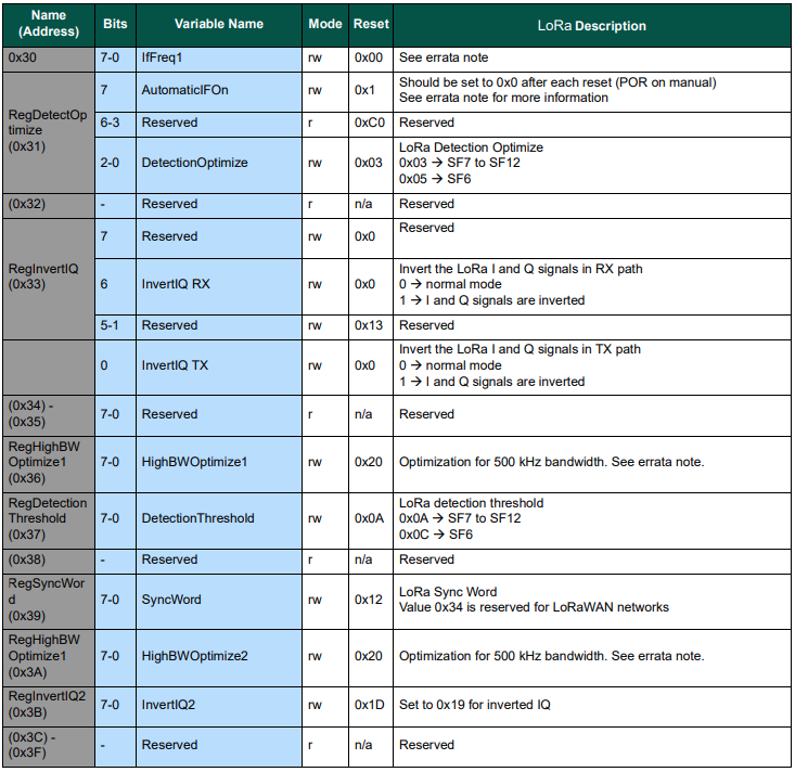
While testing the LoRaDuplex sample I found a problem with how my code managed the invertIQRX & invertIQTX flags in RegInvertIQ. I noticed the even though I was setting the InvertIQRX(bit6) and invertIQTX(bit0) flags correctly messages weren’t getting delivered.

Semtech SX127X data sheet RegInvertQ and RegInvertQ2 documetnation

After looking at my code I realised I wasn’t configuring the RegInvertIQ properly because bits 1-5 were getting set to 0x0 (initially I had byte regInvertIQValue = 0) rather than 0x13(regInvertIQValue = RegInvertIdDefault)

...
// RegInvertId
private const byte RegInvertIdDefault = 0b00100110;
private const byte InvertIqRXOn = 0b01000000;
private const byte InvertIqRXOff = 0b00000000;
public const bool InvertIqRXDefault = false;

private const byte InvertIqTXOn =  0b00000001; 
private const byte InvertIqTXOff = 0b00000000;
...

if ((invertIQRX != InvertIqRXDefault) || (invertIQTX != InvertIqTXDefault))
{
	// Initially this was byte regInvertIQValue = 0;
	byte regInvertIQValue = RegInvertIdDefault;

	if (invertIQRX)
	{
		regInvertIQValue |= InvertIqRXOn;
	}

	if (invertIQTX)
	{
		regInvertIQValue |= InvertIqTXOn;
	}

	this.WriteByte((byte)Registers.RegInvertIQ, regInvertIQValue);

	if (invertIQRX || invertIQTX)
	{
		this.WriteByte((byte)Registers.RegInvertIQ2, RegInvertIq2On);
	}
	else
	{
		this.WriteByte((byte)Registers.RegInvertIQ2, RegInvertIq2Off);
	}
}

.NET Core SX127X library Arduino LoRaSimpleNode & LoRaSimpleGateway

The LoRaSimpleNode and LoRaSimpleGateway samples shows how the receive and transmit IQ can be inverted.

LoRaSimpleNode

This sample uses all default settings except for frequency with InvertIQ enabled in receive more and disabled in Transmit mode

void loop() {
  if (runEvery(1000)) { // repeat every 1000 millis

    String message = "HeLoRa World! ";
    message += "I'm a Node! ";
    message += millis();

    LoRa_sendMessage(message); // send a message

    Serial.println("Send Message!");
  }
}

void LoRa_rxMode(){
  LoRa.enableInvertIQ();                // active invert I and Q signals
  LoRa.receive();                       // set receive mode
}

void LoRa_txMode(){
  LoRa.idle();                          // set standby mode
  LoRa.disableInvertIQ();               // normal mode
}

void LoRa_sendMessage(String message) {
  LoRa_txMode();                        // set tx mode
  LoRa.beginPacket();                   // start packet
  LoRa.print(message);                  // add payload
  LoRa.endPacket();                     // finish packet and send it
  LoRa_rxMode();                        // set rx mode
}

void onReceive(int packetSize) {
  String message = "";

  while (LoRa.available()) {
    message += (char)LoRa.read();
  }

  Serial.print("Node Receive: ");
  Serial.println(message);

}
Arduino Monitor displaying the output of the Arduino-LoRa Simple Node sample

In the Visual Studio output window I could see the received messages.

Loaded '/usr/lib/dotnet/shared/Microsoft.NETCore.App/5.0.4/Microsoft.Win32.Primitives.dll'. Skipped loading symbols. Module is optimized and the debugger option 'Just My Code' is enabled.
17:46:31-RX length 31 "HeLoRa World! I'm a Node! 69000" snr 10.3 packet rssi -57dBm rssi -98dBm 
17:46:32-RX length 31 "HeLoRa World! I'm a Node! 70000" snr 9.8 packet rssi -56dBm rssi -104dBm 
17:46:33-RX length 31 "HeLoRa World! I'm a Node! 71000" snr 10.0 packet rssi -57dBm rssi -104dBm 
17:46:34-RX length 31 "HeLoRa World! I'm a Node! 72000" snr 9.8 packet rssi -56dBm rssi -102dBm 
17:46:35-RX length 31 "HeLoRa World! I'm a Node! 73000" snr 9.8 packet rssi -59dBm rssi -102dBm 
17:46:36- Length 28 "Hello LoRa from .NET Core! 1"
17:46:36-TX Done
17:46:37-RX length 31 "HeLoRa World! I'm a Node! 75000" snr 9.3 packet rssi -58dBm rssi -102dBm 
17:46:38-RX length 31 "HeLoRa World! I'm a Node! 76000" snr 9.0 packet rssi -58dBm rssi -102dBm 
17:46:39-RX length 31 "HeLoRa World! I'm a Node! 77000" snr 9.8 packet rssi -59dBm rssi -104dBm 
17:46:40-RX length 31 "HeLoRa World! I'm a Node! 78000" snr 9.5 packet rssi -57dBm rssi -102dBm 
17:46:41-RX length 31 "HeLoRa World! I'm a Node! 79000" snr 9.5 packet rssi -55dBm rssi -102dBm 
17:46:42-RX length 31 "HeLoRa World! I'm a Node! 80000" snr 9.8 packet rssi -57dBm rssi -104dBm 
17:46:43-RX length 31 "HeLoRa World! I'm a Node! 81000" snr 9.5 packet rssi -58dBm rssi -104dBm 
17:46:44-RX length 31 "HeLoRa World! I'm a Node! 82000" snr 9.5 packet rssi -58dBm rssi -104dBm 
17:46:45-RX length 31 "HeLoRa World! I'm a Node! 83000" snr 9.0 packet rssi -58dBm rssi -94dBm 
17:46:46- Length 28 "Hello LoRa from .NET Core! 2"
17:46:46-TX Done
17:46:47-RX length 31 "HeLoRa World! I'm a Node! 85000" snr 9.0 packet rssi -58dBm rssi -104dBm 
17:46:48-RX length 31 "HeLoRa World! I'm a Node! 86000" snr 9.5 packet rssi -58dBm rssi -104dBm 
17:46:49-RX length 31 "HeLoRa World! I'm a Node! 87000" snr 9.5 packet rssi -58dBm rssi -102dBm 
17:46:50-RX length 30 "HeLoRa World! I'm a Node! 1000" snr 9.5 packet rssi -58dBm rssi -102dBm 
17:46:51-RX length 30 "HeLoRa World! I'm a Node! 2000" snr 9.5 packet rssi -58dBm rssi -104dBm 
17:46:52-RX length 30 "HeLoRa World! I'm a Node! 3000" snr 9.3 packet rssi -58dBm rssi -102dBm 
17:46:53-RX length 30 "HeLoRa World! I'm a Node! 4000" snr 9.5 packet rssi -58dBm rssi -102dBm 
17:46:54-RX length 30 "HeLoRa World! I'm a Node! 5000" snr 10.0 packet rssi -57dBm rssi -102dBm 
17:46:55-RX length 30 "HeLoRa World! I'm a Node! 6000" snr 10.0 packet rssi -57dBm rssi -102dBm 
17:46:56- Length 28 "Hello LoRa from .NET Core! 3"
17:46:56-TX Done
17:46:56-RX length 30 "HeLoRa World! I'm a Node! 7000" snr 9.8 packet rssi -57dBm rssi -104dBm 
17:46:57-RX length 30 "HeLoRa World! I'm a Node! 8000" snr 10.0 packet rssi -57dBm rssi -102dBm 
17:46:58-RX length 30 "HeLoRa World! I'm a Node! 9000" snr 9.8 packet rssi -57dBm rssi -104dBm 
17:46:59-RX length 31 "HeLoRa World! I'm a Node! 10000" snr 9.8 packet rssi -57dBm rssi -100dBm 
17:47:00-RX length 31 "HeLoRa World! I'm a Node! 11000" snr 9.8 packet rssi -57dBm rssi -99dBm 
17:47:01-RX length 31 "HeLoRa World! I'm a Node! 12000" snr 9.3 packet rssi -57dBm rssi -104dBm 
17:47:04-RX length 30 "HeLoRa World! I'm a Node! 1000" snr 9.5 packet rssi -57dBm rssi -100dBm 
17:47:05-RX length 30 "HeLoRa World! I'm a Node! 2000" snr 10.0 packet rssi -57dBm rssi -100dBm 
17:47:06- Length 28 "Hello LoRa from .NET Core! 4"
17:47:06-TX Done

LoRaSimpleGateway

The SimpleGateway uses all the same settings but with InvertIQ enabled in Transmit mode and disabled in Receive mode

#include <SPI.h>              // include libraries
#include <LoRa.h>

const long frequency = 915E6;  // LoRa Frequency

const int csPin = 10;          // LoRa radio chip select
const int resetPin = 9;        // LoRa radio reset
const int irqPin = 2;          // change for your board; must be a hardware interrupt pin

void setup() {
  Serial.begin(9600);                   // initialize serial
  while (!Serial);

  LoRa.setPins(csPin, resetPin, irqPin);

  if (!LoRa.begin(frequency)) {
    Serial.println("LoRa init failed. Check your connections.");
    while (true);                       // if failed, do nothing
  }

  Serial.println("LoRa init succeeded.");
  Serial.println();
  Serial.println("LoRa Simple Gateway");
  Serial.println("Only receive messages from nodes");
  Serial.println("Tx: invertIQ enable");
  Serial.println("Rx: invertIQ disable");
  Serial.println();

  LoRa.onReceive(onReceive);
  LoRa_rxMode();
}

void loop() {
  if (runEvery(5000)) { // repeat every 5000 millis

    String message = "HeLoRa World! ";
    message += "I'm a Gateway! ";
    message += millis();

    LoRa_sendMessage(message); // send a message

    Serial.println("Send Message!");
  }
}

void LoRa_rxMode(){
  LoRa.disableInvertIQ();               // normal mode
  LoRa.receive();                       // set receive mode
}

void LoRa_txMode(){
  LoRa.idle();                          // set standby mode
  LoRa.enableInvertIQ();                // active invert I and Q signals
}

void LoRa_sendMessage(String message) {
  LoRa_txMode();                        // set tx mode
  LoRa.beginPacket();                   // start packet
  LoRa.print(message);                  // add payload
  LoRa.endPacket();                     // finish packet and send it
  LoRa_rxMode();                        // set rx mode
}

void onReceive(int packetSize) {
  String message = "";

  while (LoRa.available()) {
    message += (char)LoRa.read();
  }

  Serial.print("Gateway Receive: ");
  Serial.println(message);
}

Arduino Monitor displaying the output of the Arduino-LoRa Simple Gateway sample

In the Visual Studio output window I could see messages getting transmitted with sent confirmations.

Loaded '/usr/lib/dotnet/shared/Microsoft.NETCore.App/5.0.4/Microsoft.Win32.Primitives.dll'. Skipped loading symbols. Module is optimized and the debugger option 'Just My Code' is enabled.
17:51:39-RX length 34 "HeLoRa World! I'm a Gateway! 10000" snr 9.3 packet rssi -59dBm rssi -102dBm 
17:51:39- Length 28 "Hello LoRa from .NET Core! 1"
17:51:39-TX Done
17:51:44-RX length 34 "HeLoRa World! I'm a Gateway! 15000" snr 9.3 packet rssi -58dBm rssi -102dBm 
17:51:49-RX length 34 "HeLoRa World! I'm a Gateway! 20000" snr 9.3 packet rssi -59dBm rssi -100dBm 
17:51:49- Length 28 "Hello LoRa from .NET Core! 2"
17:51:49-TX Done
17:51:54-RX length 34 "HeLoRa World! I'm a Gateway! 25000" snr 9.0 packet rssi -58dBm rssi -102dBm 
17:51:59-RX length 34 "HeLoRa World! I'm a Gateway! 30000" snr 9.3 packet rssi -58dBm rssi -100dBm 
17:51:59- Length 28 "Hello LoRa from .NET Core! 3"
17:51:59-TX Done
17:52:04-RX length 34 "HeLoRa World! I'm a Gateway! 35000" snr 9.3 packet rssi -60dBm rssi -104dBm 
17:52:09-RX length 34 "HeLoRa World! I'm a Gateway! 40000" snr 9.5 packet rssi -59dBm rssi -104dBm 
17:52:09- Length 28 "Hello LoRa from .NET Core! 4"
17:52:09-TX Done
17:52:14-RX length 34 "HeLoRa World! I'm a Gateway! 45000" snr 9.5 packet rssi -59dBm rssi -102dBm 
17:52:19-RX length 34 "HeLoRa World! I'm a Gateway! 50000" snr 9.3 packet rssi -60dBm rssi -104dBm 
17:52:19- Length 28 "Hello LoRa from .NET Core! 5"
17:52:19-TX Done
17:52:24-RX length 34 "HeLoRa World! I'm a Gateway! 55000" snr 9.8 packet rssi -60dBm rssi -102dBm 
17:52:29-RX length 34 "HeLoRa World! I'm a Gateway! 60000" snr 9.3 packet rssi -60dBm rssi -104dBm 
17:52:29- Length 28 "Hello LoRa from .NET Core! 6"
17:52:29-TX Done
17:52:34-RX length 34 "HeLoRa World! I'm a Gateway! 65000" snr 9.0 packet rssi -60dBm rssi -102dBm 
17:52:39-RX length 34 "HeLoRa World! I'm a Gateway! 70000" snr 9.3 packet rssi -60dBm rssi -102dBm 
17:52:39- Length 28 "Hello LoRa from .NET Core! 7"
17:52:39-TX Done
17:52:44-RX length 34 "HeLoRa World! I'm a Gateway! 75000" snr 8.8 packet rssi -58dBm rssi -102dBm 
17:52:49-RX length 34 "HeLoRa World! I'm a Gateway! 80000" snr 9.0 packet rssi -59dBm rssi -102dBm 
17:52:49- Length 28 "Hello LoRa from .NET Core! 8"
17:52:49-TX Done
17:52:54-RX length 34 "HeLoRa World! I'm a Gateway! 85000" snr 9.8 packet rssi -60dBm rssi -102dBm 
17:52:59-RX length 34 "HeLoRa World! I'm a Gateway! 90000" snr 9.0 packet rssi -60dBm rssi -102dBm 
17:52:59- Length 28 "Hello LoRa from .NET Core! 9"
17:52:59-TX Done
17:53:04-RX length 34 "HeLoRa World! I'm a Gateway! 95000" snr 9.3 packet rssi -59dBm rssi -100dBm 
17:53:09-RX length 35 "HeLoRa World! I'm a Gateway! 100000" snr 9.0 packet rssi -59dBm rssi -102dBm 
17:53:09- Length 29 "Hello LoRa from .NET Core! 10"
17:53:09-TX Done
17:53:14-RX length 35 "HeLoRa World! I'm a Gateway! 105000" snr 9.5 packet rssi -56dBm rssi -102dBm 
17:53:19-RX length 35 "HeLoRa World! I'm a Gateway! 110000" snr 9.3 packet rssi -59dBm rssi -102dBm 
17:53:19- Length 29 "Hello LoRa from .NET Core! 11"
17:53:19-TX Done

I then modified the SX127X.NetCore SX127XLoRaDeviceClient adding even more conditional compile options for the LoRaSampleNode and LoRaSampleGateway samples.

int messageCount = 1;

sX127XDevice.Initialise(
		SX127XDevice.RegOpModeMode.ReceiveContinuous,
		915000000.0,
		powerAmplifier: SX127XDevice.PowerAmplifier.PABoost,
		// outputPower: 5, outputPower: 20, outputPower:23,
		//powerAmplifier: SX127XDevice.PowerAmplifier.Rfo,	
		//outputPower:-1, outputPower: 14,
#if LORA_SENDER // From the Arduino point of view
		rxDoneignoreIfCrcMissing: false
#endif
#if LORA_RECEIVER // From the Arduino point of view, don't actually need this as already inverted
		invertIQTX: true
#endif

#if LORA_SET_SYNCWORD
		syncWord: 0xF3,
		invertIQTX: true,
		rxDoneignoreIfCrcMissing: false
#endif
#if LORA_SET_SPREAD
		spreadingFactor: SX127XDevice.RegModemConfig2SpreadingFactor._256ChipsPerSymbol,
		invertIQTX: true,
		rxDoneignoreIfCrcMissing: false
#endif
#if LORA_SIMPLE_NODE // From the Arduino point of view
		invertIQTX: false,
		rxDoneignoreIfCrcMissing: false
#endif
#if LORA_SIMPLE_GATEWAY // From the Arduino point of view
		invertIQRX: true,
		rxDoneignoreIfCrcMissing: false
#endif
		);

#if DEBUG
		sX127XDevice.RegisterDump();
#endif

#if !LORA_RECEIVER
		sX127XDevice.OnReceive += SX127XDevice_OnReceive;
		sX127XDevice.Receive();
#endif
#if !LORA_SENDER
		sX127XDevice.OnTransmit += SX127XDevice_OnTransmit;
#endif

#if LORA_SENDER
		Thread.Sleep(-1);
#else
		Thread.Sleep(5000);
#endif

		while (true)
		{
			string messageText = "Hello LoRa from .NET Core! " + messageCount.ToString();

			byte[] messageBytes = UTF8Encoding.UTF8.GetBytes(messageText);

			Console.WriteLine($"{DateTime.Now:HH:mm:ss}- Length {messageBytes.Length} \"{messageText}\"");

			messageCount += 1;

			sX127XDevice.Send(messageBytes);

			Thread.Sleep(10000);
		}
	}

Summary

While testing the LoRaReceiver sample I found a problem with how my code managed the transmit power by accidentally commenting out the “paBoost: true” parameter of the initialise method. When I did this the Seeeduino V4.2 and Dragino Shield stopped receiving messages.

I had assumed a user could configure the the output power using the initialise method but that was difficult/possible. After some digging I found that I needed to use RegPAConfigPADac and PABoost (I need to find a device which uses RFO for testing). So I removed several of the configuration parameters from the Intialise method and replaced them with one called outputPower. I then re-read the SX127X data sheet and had a look at some other libraries.

The Arduino-LoRa code has SetPower

void LoRaClass::setTxPower(int level, int outputPin)
{
  if (PA_OUTPUT_RFO_PIN == outputPin) {
    // RFO
    if (level < 0) {
      level = 0;
    } else if (level > 14) {
      level = 14;
    }

    writeRegister(REG_PA_CONFIG, 0x70 | level);
  } else {
    // PA BOOST
    if (level > 17) {
      if (level > 20) {
        level = 20;
      }

      // subtract 3 from level, so 18 - 20 maps to 15 - 17
      level -= 3;

      // High Power +20 dBm Operation (Semtech SX1276/77/78/79 5.4.3.)
      writeRegister(REG_PA_DAC, 0x87);
      setOCP(140);
    } else {
      if (level < 2) {
        level = 2;
      }
      //Default value PA_HF/LF or +17dBm
      writeRegister(REG_PA_DAC, 0x84);
      setOCP(100);
    }

    writeRegister(REG_PA_CONFIG, PA_BOOST | (level - 2));
  }
}

The AdaFruit version of RadioHead library has SetTxPower which has been “tweaked”

void RH_RF95::setTxPower(int8_t power, bool useRFO)
{
    // Sigh, different behaviours depending on whther the module use PA_BOOST or the RFO pin
    // for the transmitter output
    if (useRFO)
    {
	if (power > 14)
	    power = 14;
	if (power < -1)
	    power = -1;
	spiWrite(RH_RF95_REG_09_PA_CONFIG, RH_RF95_MAX_POWER | (power + 1));
    }
    else
    {
	if (power > 23)
	    power = 23;
	if (power < 5)
	    power = 5;

	// For RH_RF95_PA_DAC_ENABLE, manual says '+20dBm on PA_BOOST when OutputPower=0xf'
	// RH_RF95_PA_DAC_ENABLE actually adds about 3dBm to all power levels. We will us it
	// for 21, 22 and 23dBm
	if (power > 20)
	{
	    spiWrite(RH_RF95_REG_4D_PA_DAC, RH_RF95_PA_DAC_ENABLE);
	    power -= 3;
	}
	else
	{
	    spiWrite(RH_RF95_REG_4D_PA_DAC, RH_RF95_PA_DAC_DISABLE);
	}

	// RFM95/96/97/98 does not have RFO pins connected to anything. Only PA_BOOST
	// pin is connected, so must use PA_BOOST
	// Pout = 2 + OutputPower.
	// The documentation is pretty confusing on this topic: PaSelect says the max power is 20dBm,
	// but OutputPower claims it would be 17dBm.
	// My measurements show 20dBm is correct
	spiWrite(RH_RF95_REG_09_PA_CONFIG, RH_RF95_PA_SELECT | (power-5));
    }
}

The LoRa Shield Arduino library has two methods setPower(char p) and setPowerNum(uint8_t pow)

/*
 Function: Sets the signal power indicated as input to the module.
 Returns: Integer that determines if there has been any error
   state = 2  --> The command has not been executed
   state = 1  --> There has been an error while executing the command
   state = 0  --> The command has been executed with no errors
   state = -1 --> Forbidden command for this protocol
 Parameters:
   pow: power option to set in configuration. The input value range is from 
   0 to 14 dBm.
*/
int8_t SX1278::setPowerNum(uint8_t pow)
{
  byte st0;
  int8_t state = 2;
  byte value = 0x00;

  #if (SX1278_debug_mode > 1)
	  Serial.println();
	  Serial.println(F("Starting 'setPower'"));
  #endif

  st0 = readRegister(REG_OP_MODE);	  // Save the previous status
  if( _modem == LORA )
  { // LoRa Stdby mode to write in registers
	  writeRegister(REG_OP_MODE, LORA_STANDBY_MODE);
  }
  else
  { // FSK Stdby mode to write in registers
	  writeRegister(REG_OP_MODE, FSK_STANDBY_MODE);
  }
  
  if ( (pow >= 2) && (pow <= 20) )
  { // Pout= 17-(15-OutputPower) = OutputPower+2
	  if ( pow <= 17 ) {
		writeRegister(REG_PA_DAC, 0x84);
	  	pow = pow - 2;
	  } else { // Power > 17dbm -> Power = 20dbm
		writeRegister(REG_PA_DAC, 0x87);
		pow = 15;
	  }
	  _power = pow;
  }
  else
  {
	  state = -1;
	  #if (SX1278_debug_mode > 1)
		  Serial.println(F("## Power value is not valid ##"));
		  Serial.println();
	  #endif
  }

  writeRegister(REG_PA_CONFIG, _power);	// Setting output power value
  value = readRegister(REG_PA_CONFIG);

  if( value == _power )
  {
	  state = 0;
	  #if (SX1278_debug_mode > 1)
		  Serial.println(F("## Output power has been successfully set ##"));
		  Serial.println();
	  #endif
  }
  else
  {
	  state = 1;
  }

  writeRegister(REG_OP_MODE, st0);	// Getting back to previous status
  return state;
}

The SEMTECH library(V2.1.0) manages sleeping the device, reading the existing configuration and updating it as required which was a bit more functionality that I wanted.

void SX1276LoRaSetRFPower( int8_t power )
{
    SX1276Read( REG_LR_PACONFIG, &SX1276LR->RegPaConfig );
    SX1276Read( REG_LR_PADAC, &SX1276LR->RegPaDac );
    
    if( ( SX1276LR->RegPaConfig & RFLR_PACONFIG_PASELECT_PABOOST ) == RFLR_PACONFIG_PASELECT_PABOOST )
    {
        if( ( SX1276LR->RegPaDac & 0x87 ) == 0x87 )
        {
            if( power < 5 )
            {
                power = 5;
            }
            if( power > 20 )
            {
                power = 20;
            }
            SX1276LR->RegPaConfig = ( SX1276LR->RegPaConfig & RFLR_PACONFIG_MAX_POWER_MASK ) | 0x70;
            SX1276LR->RegPaConfig = ( SX1276LR->RegPaConfig & RFLR_PACONFIG_OUTPUTPOWER_MASK ) | ( uint8_t )( ( uint16_t )( power - 5 ) & 0x0F );
        }
        else
        {
            if( power < 2 )
            {
                power = 2;
            }
            if( power > 17 )
            {
                power = 17;
            }
            SX1276LR->RegPaConfig = ( SX1276LR->RegPaConfig & RFLR_PACONFIG_MAX_POWER_MASK ) | 0x70;
            SX1276LR->RegPaConfig = ( SX1276LR->RegPaConfig & RFLR_PACONFIG_OUTPUTPOWER_MASK ) | ( uint8_t )( ( uint16_t )( power - 2 ) & 0x0F );
        }
    }
    else
    {
        if( power < -1 )
        {
            power = -1;
        }
        if( power > 14 )
        {
            power = 14;
        }
        SX1276LR->RegPaConfig = ( SX1276LR->RegPaConfig & RFLR_PACONFIG_MAX_POWER_MASK ) | 0x70;
        SX1276LR->RegPaConfig = ( SX1276LR->RegPaConfig & RFLR_PACONFIG_OUTPUTPOWER_MASK ) | ( uint8_t )( ( uint16_t )( power + 1 ) & 0x0F );
    }
    SX1276Write( REG_LR_PACONFIG, SX1276LR->RegPaConfig );
    LoRaSettings.Power = power;
}

All the of the examples I looked at were different and some had manual tweaks, others I have not included were just wrong. I have based my beta version on a hybrid of the Arduino-LoRa, RadioHead and Semtech libraries. I need to test my code and confirm that I have the limits and offsets correct for the PABoost and RFO modes.

// RegPaDac more power
[Flags]
public enum RegPaDac
{
	Normal = 0b01010100,
	Boost = 0b01010111,
}
private const byte RegPaDacPABoostThreshold = 20;

// Validate the OutputPower
if (powerAmplifier == PowerAmplifier.Rfo)
{
	if ((outputPower < OutputPowerRfoMin) || (outputPower > OutputPowerRfoMax))
	{
		throw new ArgumentException($"outputPower must be between {OutputPowerRfoMin} and {OutputPowerRfoMax}", nameof(outputPower));
	}
}
if (powerAmplifier == PowerAmplifier.PABoost)
{
	if ((outputPower < OutputPowerPABoostMin) || (outputPower > OutputPowerPABoostMax))
	{
		throw new ArgumentException($"outputPower must be between {OutputPowerPABoostMin} and {OutputPowerPABoostMax}", nameof(outputPower));	
	}
}

if (( powerAmplifier != PowerAmplifierDefault) || (outputPower != OutputPowerDefault))
{
	byte regPAConfigValue = RegPAConfigMaxPowerMax;

	if (powerAmplifier == PowerAmplifier.Rfo)
	{
		regPAConfigValue |= RegPAConfigPASelectRfo;

		regPAConfigValue |= (byte)(outputPower + 1);

		this.WriteByte((byte)Registers.RegPAConfig, regPAConfigValue);
	}

	if (powerAmplifier == PowerAmplifier.PABoost)
	{
		regPAConfigValue |= RegPAConfigPASelectPABoost;

		if (outputPower > RegPaDacPABoostThreshold)
		{
			this.WriteByte((byte)Registers.RegPaDac, (byte)RegPaDac.Boost);

			regPAConfigValue |= (byte)(outputPower - 8);

			this.WriteByte((byte)Registers.RegPAConfig, regPAConfigValue);
		}
		else
		{
			this.WriteByte((byte)Registers.RegPaDac, (byte)RegPaDac.Normal);

			regPAConfigValue |= (byte)(outputPower - 5);

			this.WriteByte((byte)Registers.RegPAConfig, regPAConfigValue);
		}
	}
}

.NET Core SX127X library Arduino LoRaSender & LoRaReceiver

The arduino-LoRa library comes with a number of samples showing how to use its functionality. The LoRaSender and LoRaReceiver samples show the bare minimum of code required to send and receive messages.

LoRaSender

This sample uses all default settings except for frequency

#include <SPI.h>
#include <LoRa.h>

int counter = 0;

void setup() {
  Serial.begin(9600);
  while (!Serial);

  Serial.println("LoRa Sender");

  if (!LoRa.begin(915E6)) {
    Serial.println("Starting LoRa failed!");
    while (1);
  }
  
  delay(5000);  
}

void loop() {
  Serial.print("Sending packet: ");
  Serial.println(counter);

  // send packet
  LoRa.beginPacket();
  LoRa.print("hello ");
  LoRa.print(counter);
  LoRa.endPacket();

  counter++;

  delay(5000);
}

Arduino-LoRa library LoRaSender monitor output

In the Visual Studio output window I could see the received messages including a “corrupted” one which was displayed because the SX127XLoRaDeviceClient couldn’t force Cyclic Redundancy Check(CRC)s.

Loaded '/usr/lib/dotnet/shared/Microsoft.NETCore.App/5.0.4/Microsoft.Win32.Primitives.dll'. Skipped loading symbols. Module is optimized and the debugger option 'Just My Code' is enabled.
17:08:14-RX length 108 "hello 7" snr 9.3 packet rssi -63dBm rssi -102dBm 
17:08:24-RX length 108 "hello 0" snr 9.5 packet rssi -64dBm rssi -104dBm 
17:08:29-RX length 108 "hello 1" snr 9.3 packet rssi -64dBm rssi -102dBm 
17:08:34-RX length 108 "hello 2" snr 9.5 packet rssi -64dBm rssi -102dBm 
17:08:39-RX length 108 "hello 3" snr 8.5 packet rssi -61dBm rssi -104dBm 
17:08:44-RX length 108 "hello 4" snr 8.5 packet rssi -62dBm rssi -104dBm 
17:08:49-RX length 108 "hello 5" snr 9.3 packet rssi -64dBm rssi -104dBm 
17:08:54-RX length 108 "hello 6" snr 9.3 packet rssi -64dBm rssi -102dBm 
17:08:59-RX length 108 "hello 7" snr 9.3 packet rssi -64dBm rssi -102dBm 
17:09:04-RX length 108 "hello 8" snr 9.3 packet rssi -64dBm rssi -100dBm 
17:09:09-RX length 108 "hello 9" snr 9.3 packet rssi -64dBm rssi -102dBm 
17:09:14-RX length 108 "hello 10" snr 8.8 packet rssi -58dBm rssi -102dBm 
17:09:19-RX length 108 "hello 11" snr 9.3 packet rssi -60dBm rssi -104dBm 
17:09:24-RX length 108 "hello 12" snr 9.5 packet rssi -59dBm rssi -104dBm 
17:09:29-RX length 108 "hello 13" snr 9.0 packet rssi -60dBm rssi -102dBm 
17:09:34-RX length 108 "hello 14" snr 9.5 packet rssi -59dBm rssi -105dBm 
17:09:39-RX length 108 "hello 15" snr 9.0 packet rssi -57dBm rssi -102dBm 
17:09:44-RX length 108 "hello 16" snr 9.3 packet rssi -61dBm rssi -104dBm 
17:09:49-RX length 108 "hello 17" snr 9.5 packet rssi -61dBm rssi -104dBm 
17:09:54-RX length 108 "hello 18" snr 9.0 packet rssi -59dBm rssi -104dBm 
17:09:59-RX length 108 "hello 19" snr 9.3 packet rssi -61dBm rssi -102dBm 
17:10:04-RX length 108 "hello 20" snr 9.0 packet rssi -59dBm rssi -104dBm 
17:10:09-RX length 108 "hello 21" snr 9.3 packet rssi -61dBm rssi -102dBm 
17:10:14-RX length 108 "hello 22" snr 9.5 packet rssi -60dBm rssi -102dBm 
17:10:19-RX length 108 "hello 23" snr 9.3 packet rssi -60dBm rssi -104dBm 
17:10:24-RX length 108 "hello 24" snr 9.3 packet rssi -60dBm rssi -103dBm 
17:10:26-RX length 212 "�Q�Ԕv&G=����[9Y���
2S��ᒵ��O*�Ϥ��X��p쏊��" snr 50.8 packet rssi -104dBm rssi -102dBm 
17:10:30-RX length 108 "hello 25" snr 9.5 packet rssi -60dBm rssi -102dBm 
17:10:35-RX length 108 "hello 26" snr 9.3 packet rssi -60dBm rssi -104dBm 

LoRaReceiver

This sample also uses all default settings except of the frequency

#include <SPI.h>
#include <LoRa.h>

void setup() {
  Serial.begin(9600);
  while (!Serial);

  Serial.println("LoRa Receiver");

  if (!LoRa.begin(915E6)) {
    Serial.println("Starting LoRa failed!");
    while (1);
  }
}

void loop() {
  // try to parse packet
  int packetSize = LoRa.parsePacket();
  if (packetSize) {
    // received a packet
    Serial.print("Received packet '");

    // read packet
    while (LoRa.available()) {
      Serial.print((char)LoRa.read());
    }

    // print RSSI of packet
    Serial.print("' with RSSI ");
    Serial.println(LoRa.packetRssi());
  }
}
Arduino-LoRa library LoRaReceiver monitor output

In the Visual Studio output window I could see messages getting transmitted with sent confirmations.

Loaded '/usr/lib/dotnet/shared/Microsoft.NETCore.App/5.0.4/Microsoft.Win32.Primitives.dll'. Skipped loading symbols. Module is optimized and the debugger option 'Just My Code' is enabled.
17:21:19- Length 28 "Hello LoRa from .NET Core! 1"
17:21:19-TX Done
17:21:29- Length 28 "Hello LoRa from .NET Core! 2"
17:21:29-TX Done
17:21:39- Length 28 "Hello LoRa from .NET Core! 3"
17:21:39-TX Done
17:21:49- Length 28 "Hello LoRa from .NET Core! 4"
17:21:49-TX Done
17:21:59- Length 28 "Hello LoRa from .NET Core! 5"
17:21:59-TX Done
17:22:09- Length 28 "Hello LoRa from .NET Core! 6"
17:22:09-TX Done
17:22:19- Length 28 "Hello LoRa from .NET Core! 7"
17:22:19-TX Done
17:22:29- Length 28 "Hello LoRa from .NET Core! 8"
17:22:29-TX Done
17:22:39- Length 28 "Hello LoRa from .NET Core! 9"
17:22:39-TX Done
17:22:49- Length 29 "Hello LoRa from .NET Core! 10"
17:22:49-TX Done
17:22:59- Length 29 "Hello LoRa from .NET Core! 11"
17:22:59-TX Done
17:23:09- Length 29 "Hello LoRa from .NET Core! 12"
17:23:09-TX Done
17:23:19- Length 29 "Hello LoRa from .NET Core! 13"
17:23:19-TX Done
17:23:29- Length 29 "Hello LoRa from .NET Core! 14"
17:23:29-TX Done
17:23:39- Length 29 "Hello LoRa from .NET Core! 15"
17:23:39-TX Done
17:23:49- Length 29 "Hello LoRa from .NET Core! 16"
17:23:49-TX Done
17:23:59- Length 29 "Hello LoRa from .NET Core! 17"
17:23:59-TX Done
17:24:09- Length 29 "Hello LoRa from .NET Core! 18"
17:24:09-TX Done

I modified the SX127X.NetCore SX127XLoRaDeviceClient adding a conditional compile options for each sample

static void Main(string[] args)	
{
	int messageCount = 1;

	sX127XDevice.Initialise(
			SX127XDevice.RegOpModeMode.ReceiveContinuous,
			915000000.0,
			powerAmplifier: SX127XDevice.PowerAmplifier.PABoost,
#if LORA_SENDER // From the Arduino point of view
			rxDoneignoreIfCrcMissing: false
#endif
#if LORA_RECEIVER // From the Arduino point of view, don't actually need this as already inverted
			invertIQTX: true
#endif

#if LORA_SET_SYNCWORD
			syncWord: 0xF3,
			invertIQTX: true,
			rxDoneignoreIfCrcMissing: false
#endif
#if LORA_SET_SPREAD
			spreadingFactor: SX127XDevice.RegModemConfig2SpreadingFactor._256ChipsPerSymbol,
			invertIQTX: true,
			rxDoneignoreIfCrcMissing: false
#endif
	);

#if DEBUG
	sX127XDevice.RegisterDump();
#endif

#if LORA_SENDER
	sX127XDevice.OnReceive += SX127XDevice_OnReceive;
	sX127XDevice.Receive();
#endif
#if LORA_RECEIVER
	sX127XDevice.OnTransmit += SX127XDevice_OnTransmit;
#endif

#if LORA_SENDER
	Thread.Sleep(-1);
#else
	Thread.Sleep(5000);
#endif

	while (true)
	{
		string messageText = "Hello LoRa from .NET Core! " + messageCount.ToString();

		byte[] messageBytes = UTF8Encoding.UTF8.GetBytes(messageText);

		Console.WriteLine($"{DateTime.Now:HH:mm:ss}- Length {messageBytes.Length} \"{messageText}\""); 

		sX127XDevice.Send(messageBytes);

		messageCount += 1;

		Thread.Sleep(10000);
	}
}

Summary

While testing the LoRaReceiver sample I found a problem with how my code managed the RegOpMode register LoRa status value. In previous versions of the code I used RegOpModeModeDefault to manage status when the ProcessTxDone(byte IrqFlags) method completed and Receive() was called.

I had assumed that that the device would always be set with SetMode(RegOpModeModeDefault) but RegOpModeModeDefault was always RegOpModeMode.Sleep.

.NET Core SX127X library Arduino LoRaSetSpread

“Playing nice” with Arduino-LoRa Samples

The arduino-LoRa library comes with a number of samples showing how to configure a SX127X device. The LoRaSetSpread sample sets the RegModemtConfig2 (masking out previous CodingRate and ImplicitHeaderModeOn with 0xFF) to configure spreading Factor (bits 4-7) to 8 which is 256 chips/symbol.

..
void setup() {
  Serial.begin(9600);                   // initialize serial
  while (!Serial);

  Serial.println("LoRa Duplex - Set spreading factor");

  // override the default CS, reset, and IRQ pins (optional)
  LoRa.setPins(csPin, resetPin, irqPin); // set CS, reset, IRQ pin

  if (!LoRa.begin(915E6)) {             // initialize ratio at 915 MHz
    Serial.println("LoRa init failed. Check your connections.");
    while (true);                       // if failed, do nothing
  }

  LoRa.setSpreadingFactor(8);           // ranges from 6-12,default 7 see API docs
  Serial.println("LoRa init succeeded.");
}

In my library I use an enumeration to represent the different spreading factors to make configuration easier for humans. (the _ prefix is due to the C# language syntax)

// RegModemConfig2
public enum RegModemConfig2SpreadingFactor : byte
{
	_64ChipsPerSymbol = 0b01100000,
	_128ChipsPerSymbol = 0b01110000,
	_256ChipsPerSymbol = 0b10000000,
	_512ChipsPerSymbol = 0b10010000,
	_1024ChipsPerSymbol = 0b10100000,
	_2048ChipsPerSymbol = 0b10110000,
	_4096ChipsPerSymbol = 0b11000000,
}
private const RegModemConfig2SpreadingFactor RegModemConfig2SpreadingFactorDefault = RegModemConfig2SpreadingFactor._128ChipsPerSymbol;

The SX127X.NetCore only sets the spreadingFactor, symbolTimeout, txContinuousMode, or rxPayloadCrcOn registers if any of them is different from their defaults.

// Set regModemConfig2 if any of the settings not defaults
if ((spreadingFactor != RegModemConfig2SpreadingFactorDefault) || (txContinuousMode != false) | (rxPayloadCrcOn != false) || (symbolTimeout != SymbolTimeoutDefault))
{
	byte RegModemConfig2Value = (byte)spreadingFactor;
	if (txContinuousMode)
	{
		RegModemConfig2Value |= RegModemConfig2TxContinuousModeOn;
	}
	if (rxPayloadCrcOn)
	{
		RegModemConfig2Value |= RegModemConfig2RxPayloadCrcOn;
	}
	// Get the MSB of SymbolTimeout
	byte[] symbolTimeoutBytes = BitConverter.GetBytes(symbolTimeout);

	// Only the zeroth & second bit of byte matter
	symbolTimeoutBytes[1] &= SymbolTimeoutMsbMask;
	RegModemConfig2Value |= symbolTimeoutBytes[1];
	this.WriteByte((byte)Registers.RegModemConfig2, RegModemConfig2Value);
}

I modified the SX127X.NetCore SX127XLoRaDeviceClient to change the SpreadingFactor to _256ChipsPerSymbol (0b10000000) to match the Arduino client.

...
#if UPUTRONICS_RPIPLUS_CS0 && !UPUTRONICS_RPIPLUS_CS1
	SX127XDevice sX127XDevice = new SX127XDevice(SX127XDevice.ChipSelectLine.CS0, 25);
#endif
#if UPUTRONICS_RPIPLUS_CS1 && UPUTRONICS_RPIPLUS_CS0
	SX127XDevice sX127XDevice = new SX127XDevice(SX127XDevice.ChipSelectLine.CS1, 16);
#endif

	sX127XDevice.Initialise(
		SX127XDevice.RegOpModeMode.ReceiveContinuous,
		Frequency,
		paBoost: true,
#if LORA_SET_SYNCWORD
		syncWord: 0xF3,
		invertIQTX: true,
		rxDoneignoreIfCrcMissing: false
#endif
#if LORA_SET_SPREAD
		spreadingFactor: SX127XDevice.RegModemConfig2SpreadingFactor._256ChipsPerSymbol,
		invertIQTX: true,
		rxDoneignoreIfCrcMissing: false
   );

#if DEBUG
	sX127XDevice.RegisterDump();
#endif
...

In the Visual Studio output window I could see that RegModemConfig2(0x1E) was set to 0x80.

Register dump
Register 0x01 - Value 0X85 - Bits 10000101
Register 0x02 - Value 0X1a - Bits 00011010
Register 0x03 - Value 0X0b - Bits 00001011
Register 0x04 - Value 0X00 - Bits 00000000
Register 0x05 - Value 0X52 - Bits 01010010
Register 0x06 - Value 0Xe4 - Bits 11100100
Register 0x07 - Value 0Xc0 - Bits 11000000
Register 0x08 - Value 0X00 - Bits 00000000
Register 0x09 - Value 0Xcf - Bits 11001111
Register 0x0a - Value 0X09 - Bits 00001001
Register 0x0b - Value 0X2b - Bits 00101011
Register 0x0c - Value 0X20 - Bits 00100000
Register 0x0d - Value 0X00 - Bits 00000000
Register 0x0e - Value 0X80 - Bits 10000000
Register 0x0f - Value 0X00 - Bits 00000000
Register 0x10 - Value 0X00 - Bits 00000000
Register 0x11 - Value 0X00 - Bits 00000000
Register 0x12 - Value 0X00 - Bits 00000000
Register 0x13 - Value 0X00 - Bits 00000000
Register 0x14 - Value 0X00 - Bits 00000000
Register 0x15 - Value 0X00 - Bits 00000000
Register 0x16 - Value 0X00 - Bits 00000000
Register 0x17 - Value 0X00 - Bits 00000000
Register 0x18 - Value 0X04 - Bits 00000100
Register 0x19 - Value 0X00 - Bits 00000000
Register 0x1a - Value 0X00 - Bits 00000000
Register 0x1b - Value 0X3d - Bits 00111101
Register 0x1c - Value 0X00 - Bits 00000000
Register 0x1d - Value 0X72 - Bits 01110010
Register 0x1e - Value 0X80 - Bits 10000000
Register 0x1f - Value 0X64 - Bits 01100100
Register 0x20 - Value 0X00 - Bits 00000000
Register 0x21 - Value 0X08 - Bits 00001000
Register 0x22 - Value 0X01 - Bits 00000001
Register 0x23 - Value 0Xff - Bits 11111111
Register 0x24 - Value 0X00 - Bits 00000000
Register 0x25 - Value 0X00 - Bits 00000000
Register 0x26 - Value 0X04 - Bits 00000100
Register 0x27 - Value 0X00 - Bits 00000000
Register 0x28 - Value 0X00 - Bits 00000000
Register 0x29 - Value 0X00 - Bits 00000000
Register 0x2a - Value 0X00 - Bits 00000000
Register 0x2b - Value 0X00 - Bits 00000000
Register 0x2c - Value 0X0d - Bits 00001101
Register 0x2d - Value 0X50 - Bits 01010000
Register 0x2e - Value 0X14 - Bits 00010100
Register 0x2f - Value 0X45 - Bits 01000101
Register 0x30 - Value 0X55 - Bits 01010101
Register 0x31 - Value 0Xc3 - Bits 11000011
Register 0x32 - Value 0X05 - Bits 00000101
Register 0x33 - Value 0X37 - Bits 00110111
Register 0x34 - Value 0X1c - Bits 00011100
Register 0x35 - Value 0X0a - Bits 00001010
Register 0x36 - Value 0X03 - Bits 00000011
Register 0x37 - Value 0X0a - Bits 00001010
Register 0x38 - Value 0X42 - Bits 01000010
Register 0x39 - Value 0X12 - Bits 00010010
Register 0x3a - Value 0X49 - Bits 01001001
Register 0x3b - Value 0X19 - Bits 00011001
Register 0x3c - Value 0X00 - Bits 00000000
Register 0x3d - Value 0Xaf - Bits 10101111
Register 0x3e - Value 0X00 - Bits 00000000
Register 0x3f - Value 0X00 - Bits 00000000
Register 0x40 - Value 0X00 - Bits 00000000
Register 0x41 - Value 0X00 - Bits 00000000
Register 0x42 - Value 0X12 - Bits 00010010

Loaded '/usr/lib/dotnet/shared/Microsoft.NETCore.App/5.0.4/System.Text.Encoding.Extensions.dll'. Skipped loading symbols. Module is optimized and the debugger option 'Just My Code' is enabled.
Loaded '/usr/lib/dotnet/shared/Microsoft.NETCore.App/5.0.4/Microsoft.Win32.Primitives.dll'. Skipped loading symbols. Module is optimized and the debugger option 'Just My Code' is enabled.
10:04:22-RX PacketSnr 11.8 Packet RSSI -45dBm RSSI -109dBm 15 byte message "HeLoRa World! 2"
10:04:31-RX PacketSnr 11.5 Packet RSSI -45dBm RSSI -104dBm 15 byte message "HeLoRa World! 4"
10:04:32-TX To 0x48 From 0x65 Count 108 28 bytes message Hello LoRa from .NET Core! 1
10:04:32-TX Done
10:04:41-RX PacketSnr 12.0 Packet RSSI -45dBm RSSI -104dBm 15 byte message "HeLoRa World! 6"
10:04:42-TX To 0x48 From 0x65 Count 108 28 bytes message Hello LoRa from .NET Core! 2
10:04:42-TX Done

This matched the Arduino serial monitor output.

Summary

The LoRaSetSpread sample illustrates how the SX127X.NetCore library modifies register(s) only if a value specified in the Initialise method parameter list is different from the default.

.NET Core SX127X library Arduino LoRaSetSyncWord

“Playing nice” with Arduino-LoRa Samples

The arduino-LoRa library comes with a number of samples showing how to configure a SX127X device. The LoRaSetSyncWord sample sets the RegSyncWord register to 0x53

SX127X registers including RegSyncWord
...
void setup() {
  Serial.begin(9600);                   // initialize serial
  while (!Serial);
  
  Serial.println("LoRa Duplex - Set sync word");

  // override the default CS, reset, and IRQ pins (optional)
  LoRa.setPins(csPin, resetPin, irqPin);// set CS, reset, IRQ pin

  if (!LoRa.begin(915E6)) {             // initialize ratio at 915 MHz
    Serial.println("LoRa init failed. Check your connections.");
    while (true);                       // if failed, do nothing
  }

  LoRa.setSyncWord(0xF3);           // ranges from 0-0xFF, default 0x34, see API docs
  Serial.println("LoRa init succeeded.");
}
...

I modified the SX127X.NetCore SX127XLoRaDeviceClient to change the SyncWord to 0x53 to match the Arduino client.

...
#if UPUTRONICS_RPIPLUS_CS0 && !UPUTRONICS_RPIPLUS_CS1
		SX127XDevice sX127XDevice = new SX127XDevice(SX127XDevice.ChipSelectLine.CS0, 25);
#endif
#if UPUTRONICS_RPIPLUS_CS1 && UPUTRONICS_RPIPLUS_CS0
		SX127XDevice sX127XDevice = new SX127XDevice(SX127XDevice.ChipSelectLine.CS1, 16);
#endif

		sX127XDevice.Initialise(
			SX127XDevice.RegOpModeMode.ReceiveContinuous,
			Frequency,
			paBoost: true,
#if LORA_SET_SYNCWORD
			syncWord:0x53,
			invertIQTX: true,
#endif			
			rxPayloadCrcOn:true, rxDoneignoreIfCrcMissing:false
			);

#if DEBUG
		sX127XDevice.RegisterDump();
#endif
...

The SX127X.NetCore only sets the RegSyncWord register if it is different from the 0x12 default

...
// RegSyncWordDefault 
if (syncWord != RegSyncWordDefault)
{
	this.WriteByte((byte)Registers.RegSyncWord, syncWord);
}
...

In the Visual Studio output window I could see that RegSyncWord(0x39) was set to 0x53.

...
Loaded '/usr/lib/dotnet/shared/Microsoft.NETCore.App/5.0.4/System.Memory.dll'. Skipped loading symbols. Module is optimized and the debugger option 'Just My Code' is enabled.
Register dump
Register 0x01 - Value 0X85 - Bits 10000101
Register 0x02 - Value 0X1a - Bits 00011010
Register 0x03 - Value 0X0b - Bits 00001011
Register 0x04 - Value 0X00 - Bits 00000000
Register 0x05 - Value 0X52 - Bits 01010010
Register 0x06 - Value 0Xe4 - Bits 11100100
Register 0x07 - Value 0Xc0 - Bits 11000000
Register 0x08 - Value 0X00 - Bits 00000000
Register 0x09 - Value 0Xcf - Bits 11001111
Register 0x0a - Value 0X09 - Bits 00001001
Register 0x0b - Value 0X2b - Bits 00101011
Register 0x0c - Value 0X20 - Bits 00100000
Register 0x0d - Value 0X00 - Bits 00000000
Register 0x0e - Value 0X80 - Bits 10000000
Register 0x0f - Value 0X00 - Bits 00000000
Register 0x10 - Value 0X00 - Bits 00000000
Register 0x11 - Value 0X00 - Bits 00000000
Register 0x12 - Value 0X00 - Bits 00000000
Register 0x13 - Value 0X00 - Bits 00000000
Register 0x14 - Value 0X00 - Bits 00000000
Register 0x15 - Value 0X00 - Bits 00000000
Register 0x16 - Value 0X00 - Bits 00000000
Register 0x17 - Value 0X00 - Bits 00000000
Register 0x18 - Value 0X04 - Bits 00000100
Register 0x19 - Value 0X00 - Bits 00000000
Register 0x1a - Value 0X00 - Bits 00000000
Register 0x1b - Value 0X39 - Bits 00111001
Register 0x1c - Value 0X00 - Bits 00000000
Register 0x1d - Value 0X72 - Bits 01110010
Register 0x1e - Value 0X74 - Bits 01110100
Register 0x1f - Value 0X64 - Bits 01100100
Register 0x20 - Value 0X00 - Bits 00000000
Register 0x21 - Value 0X08 - Bits 00001000
Register 0x22 - Value 0X01 - Bits 00000001
Register 0x23 - Value 0Xff - Bits 11111111
Register 0x24 - Value 0X00 - Bits 00000000
Register 0x25 - Value 0X00 - Bits 00000000
Register 0x26 - Value 0X04 - Bits 00000100
Register 0x27 - Value 0X00 - Bits 00000000
Register 0x28 - Value 0X00 - Bits 00000000
Register 0x29 - Value 0X00 - Bits 00000000
Register 0x2a - Value 0X00 - Bits 00000000
Register 0x2b - Value 0X00 - Bits 00000000
Register 0x2c - Value 0X1a - Bits 00011010
Register 0x2d - Value 0X50 - Bits 01010000
Register 0x2e - Value 0X14 - Bits 00010100
Register 0x2f - Value 0X45 - Bits 01000101
Register 0x30 - Value 0X55 - Bits 01010101
Register 0x31 - Value 0Xc3 - Bits 11000011
Register 0x32 - Value 0X05 - Bits 00000101
Register 0x33 - Value 0X37 - Bits 00110111
Register 0x34 - Value 0X1c - Bits 00011100
Register 0x35 - Value 0X0a - Bits 00001010
Register 0x36 - Value 0X03 - Bits 00000011
Register 0x37 - Value 0X0a - Bits 00001010
Register 0x38 - Value 0X42 - Bits 01000010
Register 0x39 - Value 0X53 - Bits 01010011
Register 0x3a - Value 0X49 - Bits 01001001
Register 0x3b - Value 0X19 - Bits 00011001
Register 0x3c - Value 0X00 - Bits 00000000
Register 0x3d - Value 0Xaf - Bits 10101111
Register 0x3e - Value 0X00 - Bits 00000000
Register 0x3f - Value 0X00 - Bits 00000000
Register 0x40 - Value 0X00 - Bits 00000000
Register 0x41 - Value 0X00 - Bits 00000000
Register 0x42 - Value 0X12 - Bits 00010010

Loaded '/usr/lib/dotnet/shared/Microsoft.NETCore.App/5.0.4/System.Text.Encoding.Extensions.dll'. Skipped loading symbols. Module is optimized and the debugger option 'Just My Code' is enabled.
Loaded '/usr/lib/dotnet/shared/Microsoft.NETCore.App/5.0.4/Microsoft.Win32.Primitives.dll'. Skipped loading symbols. Module is optimized and the debugger option 'Just My Code' is enabled.
18:22:42-RX PacketSnr 10.0 Packet RSSI -48dBm RSSI -104dBm 15 byte message "HeLoRa World! 0"
Sending 28 bytes message Hello LoRa from .NET Core! 1
18:22:42-TX Done
Sending 28 bytes message Hello LoRa from .NET Core! 2
18:22:52-TX Done
18:22:53-RX PacketSnr 9.8 Packet RSSI -46dBm RSSI -103dBm 15 byte message "HeLoRa World! 2"
Sending 28 bytes message Hello LoRa from .NET Core! 3
18:23:02-TX Done
18:23:04-RX PacketSnr 10.0 Packet RSSI -46dBm RSSI -104dBm 15 byte message "HeLoRa World! 4"
Sending 28 bytes message Hello LoRa from .NET Core! 4
18:23:12-TX Done
18:23:14-RX PacketSnr 9.5 Packet RSSI -46dBm RSSI -104dBm 15 byte message "HeLoRa World! 6"
Sending 28 bytes message Hello LoRa from .NET Core! 5
18:23:22-TX Done
18:23:26-RX PacketSnr 10.0 Packet RSSI -47dBm RSSI -105dBm 15 byte message "HeLoRa World! 8"
Sending 28 bytes message Hello LoRa from .NET Core! 6
18:23:32-TX Done
18:23:37-RX PacketSnr 10.0 Packet RSSI -48dBm RSSI -104dBm 16 byte message "HeLoRa World! 10"
Sending 28 bytes message Hello LoRa from .NET Core! 7
18:23:42-TX Done
18:23:48-RX PacketSnr 9.8 Packet RSSI -48dBm RSSI -104dBm 16 byte message "HeLoRa World! 12"
Sending 28 bytes message Hello LoRa from .NET Core! 8
18:23:52-TX Done
18:24:00-RX PacketSnr 12.5 Packet RSSI -48dBm RSSI -104dBm 16 byte message "HeLoRa World! 14"
Sending 28 bytes message Hello LoRa from .NET Core! 9
18:24:02-TX Done
18:24:11-RX PacketSnr 10.0 Packet RSSI -47dBm RSSI -104dBm 16 byte message "HeLoRa World! 16"
Sending 29 bytes message Hello LoRa from .NET Core! 10
18:24:12-TX Done
Sending 29 bytes message Hello LoRa from .NET Core! 11
18:24:22-TX Done
18:24:23-RX PacketSnr 9.3 Packet RSSI -49dBm RSSI -104dBm 16 byte message "HeLoRa World! 18"
Sending 29 bytes message Hello LoRa from .NET Core! 12
18:24:32-TX Done
18:24:34-RX PacketSnr 9.5 Packet RSSI -49dBm RSSI -104dBm 16 byte message "HeLoRa World! 20"
Sending 29 bytes message Hello LoRa from .NET Core! 13
18:24:42-TX Done
18:24:45-RX PacketSnr 9.3 Packet RSSI -49dBm RSSI -104dBm 16 byte message "HeLoRa World! 22"
Sending 29 bytes message Hello LoRa from .NET Core! 14
18:24:52-TX Done
The thread 0x74ab has exited with code 0 (0x0).
18:24:55-RX PacketSnr 9.5 Packet RSSI -49dBm RSSI -103dBm 16 byte message "HeLoRa World! 24"
The program 'dotnet' has exited with code 0 (0x0).

This matched the Arduino serial monitor output.

Arduino-Lora LoRaSetSyncWord serial monitor

Summary

Usually the SX127X.NetCore library modifies register(s) only if a value specified in the Initialise method parameter list is different from the default.

Some values span multiple registers e.g. frequency uses RegFrMsb, RegFrMid & RegFrLsb, and multiple options can be specified in a single register e.g. RegOpMode which complicates the code.

Note the SyncWord only a byte….

.NET Core SX127X library Part6

Enumerations, Constants and Masks

This was a huge (and tedious) task. I went thru the SX127X datasheet and created enumerations, masks, flags, defaults, and constants for most of the LoRa mode configuration options. The list of LoRa registers with a brief overview of each one starts on page 108 and finishes on page 115 of the datasheet.

SX127X data sheet page 108 Register 0x0 to 0x07

The registers enumeration is approximately fifty lines long, some of which I have ignored because I don’t need them or I can’t figure out what they do.

		// Registers from SemTech SX127X Datasheet
		enum Registers : byte
		{
			MinValue = RegOpMode,

			RegFifo = 0x0,
			RegOpMode = 0x01,
			//Reserved 0x02-0x06 
			RegFrMsb = 0x06,
			RegFrMid = 0x7,
			RegFrLsb = 0x08,
			RegPAConfig = 0x09,
			//RegPARamp = 0x0A, // not included as FSK/OOK functionality
			RegOcp = 0x0B,
			RegLna = 0x0C,
			RegFifoAddrPtr = 0x0D,
			RegFifoTxBaseAddr = 0x0E,
			RegFifoRxCurrent = 0x10,
			RegIrqFlagsMask = 0x11,
			RegIrqFlags = 0x12,
			RegRxNbBytes = 0x13,
			// RegRxHeaderCntValueMsb=0x14
			// RegRxHeaderCntValueLsb=0x15
			// RegRxPacketCntValueMsb=0x16
			// RegRxPacketCntValueMsb=0x17
			// RegModemStat=0x18
			RegPktSnrValue=0x19,
			RegPktRssiValue=0x1A,
			RegRssiValue=0x1B,
			RegHopChannel=0x1C,
			RegModemConfig1 = 0x1D,
			RegModemConfig2 = 0x1E,
			RegSymbTimeout = 0x1F,
			RegPreambleMsb = 0x20,
			RegPreambleLsb = 0x21,
			RegPayloadLength = 0x22,
			RegMaxPayloadLength = 0x23,
			RegHopPeriod = 0x24,
			// RegFifiRxByteAddr = 0x25
			RegModemConfig3 = 0x26,
			RegPpmCorrection = 0x27,
			// RegFeiMsb = 0x28
			// RegFeiMid = 0x29
			// RegFeiLsb = 0x2A
			// Reserved 0x2B
			// RegRssiWideband = 0x2C
			// Reserved 0x2D-0x30
			RegDetectOptimize = 0x31,
			// Reserved 0x32
			RegInvertIQ = 0x33,
			// Reserved 0x34-0x36
			RegDetectionThreshold = 0x37,
			// Reserved 0x38
			RegSyncWord = 0x39,
			RegInvertIQ2 = 0x3B,
			RegDioMapping1 = 0x40,
			RegVersion = 0x42,

			MaxValue = RegVersion,
		}

For each register I worked out from the documentation what it was used for, did I need to implement it and if so how. For example RegOpMode controls the operating mode of the module and has a state machine as well

		// RegOpMode mode flags
		private const byte RegOpModeLongRangeModeLoRa = 0b10000000;
		private const byte RegOpModeLongRangeModeFskOok = 0b00000000;
		private const byte RegOpModeLongRangeModeDefault = RegOpModeLongRangeModeFskOok;

		private const byte RegOpModeAcessSharedRegLoRa = 0b00000000;
		private const byte RegOpModeAcessSharedRegFsk = 0b01000000;
		private const byte RegOpModeAcessSharedRegDefault = RegOpModeAcessSharedRegLoRa;

		private const byte RegOpModeLowFrequencyModeOnHighFrequency = 0b00000000;
		private const byte RegOpModeLowFrequencyModeOnLowFrequency = 0b00001000;
		private const byte RegOpModeLowFrequencyModeOnDefault = RegOpModeLowFrequencyModeOnLowFrequency;

		[Flags]
		public enum RegOpModeMode : byte
		{
			Sleep = 0b00000000,
			StandBy = 0b00000001,
			FrequencySynthesisTX = 0b00000010,
			Transmit = 0b00000011,
			FrequencySynthesisRX = 0b00000100,
			ReceiveContinuous = 0b00000101,
			ReceiveSingle = 0b00000110,
			ChannelActivityDetection = 0b00000111,
		};

		// Frequency configuration magic numbers from Semtech SX127X specs
		private const double SX127X_FXOSC = 32000000.0;
		private const double SX127X_FSTEP = SX127X_FXOSC / 524288.0;
		private const double SX127XMidBandThreshold = 525000000.0; // Search for RF_MID_BAND_THRESH GitHub LoRaNet LoRaMac-node/src/boards/sx1276-board.h
		private const int RssiAdjustmentHF = -157;
		private const int RssiAdjustmentLF = -164;

		// RegFrMsb, RegFrMid, RegFrLsb
		private const double FrequencyDefault = 434000000.0;

Some of the documentation is incredibly detailed but has little impact on my use case. (If someone needs this sort of functionality I will add it)

Some operations have state machines which add even more implementation complexity

State transition diagram for transmitting messages in LoRa mode

In my library I reset the SX127X then configure any “non-default” settings as the application starts. My applications ten to change only a limited number of registers once they are running. For any register(s) that can be changed while the application is running I have a “shadow” variable for each of them so I don’t have to read the register before writing it.

public void Initialise(RegOpModeMode modeAfterInitialise, // RegOpMode
	double frequency = FrequencyDefault, // RegFrMsb, RegFrMid, RegFrLsb
	bool rxDoneignoreIfCrcMissing = true, bool rxDoneignoreIfCrcInvalid = true,
	bool paBoost = false, byte maxPower = RegPAConfigMaxPowerDefault, byte outputPower = RegPAConfigOutputPowerDefault, // RegPaConfig
	bool ocpOn = RegOcpDefault, byte ocpTrim = RegOcpOcpTrimDefault, // RegOcp
	RegLnaLnaGain lnaGain = LnaGainDefault, bool lnaBoost = LnaBoostDefault, // RegLna
	RegModemConfigBandwidth bandwidth = RegModemConfigBandwidthDefault, RegModemConfigCodingRate codingRate = RegModemConfigCodingRateDefault, RegModemConfigImplicitHeaderModeOn implicitHeaderModeOn = RegModemConfigImplicitHeaderModeOnDefault, //RegModemConfig1
	RegModemConfig2SpreadingFactor spreadingFactor = RegModemConfig2SpreadingFactorDefault, bool txContinuousMode = false, bool rxPayloadCrcOn = false,
	ushort symbolTimeout = SymbolTimeoutDefault,
	ushort preambleLength = PreambleLengthDefault,
	byte payloadLength = PayloadLengthDefault,
	byte payloadMaxLength = PayloadMaxLengthDefault,
	byte freqHoppingPeriod = FreqHoppingPeriodDefault,
	bool lowDataRateOptimize = LowDataRateOptimizeDefault, bool agcAutoOn = AgcAutoOnDefault,
	byte ppmCorrection = ppmCorrectionDefault,
	RegDetectOptimizeDectionOptimize detectionOptimize = RegDetectOptimizeDectionOptimizeDefault,
	bool invertIQRX = InvertIqRXDefault, bool invertIQTX = InvertIqTXDefault,
	RegisterDetectionThreshold detectionThreshold = RegisterDetectionThresholdDefault,
	byte syncWord = RegSyncWordDefault)
{
	RegOpModeModeCurrent = modeAfterInitialise; // TODO 

	Frequency = frequency; // Store this away for RSSI adjustments
	RxDoneIgnoreIfCrcMissing = rxDoneignoreIfCrcMissing;
	RxDoneIgnoreIfCrcInvalid = rxDoneignoreIfCrcInvalid;
	InvertIQRX = invertIQRX;
	InvertIQTX = invertIQTX;

	// Strobe Reset pin briefly to factory reset SX127X chip
	if (ResetLogicalPinNumber != 0)
	{
		gpioController.Write(ResetLogicalPinNumber, PinValue.Low);
		Thread.Sleep(20);
		gpioController.Write(ResetLogicalPinNumber, PinValue.High);
		Thread.Sleep(20);
	}

	// Put the device into sleep mode so registers can be changed
	SetMode(RegOpModeMode.Sleep);

	// Configure RF Carrier frequency 
	if (frequency != FrequencyDefault)
	{
		byte[] bytes = BitConverter.GetBytes((long)(frequency / SX127X_FSTEP));
		this.WriteByte((byte)Registers.RegFrMsb, bytes[2]);
		this.WriteByte((byte)Registers.RegFrMid, bytes[1]);
		this.WriteByte((byte)Registers.RegFrLsb, bytes[0]);
	}
....
}

Summary

There are a huge number of configuration options for an SX127X device so my library exposes the ones required for common use cases. If a scenario is not supported the ReadByte, ReadBytes, ReadWordMsbLsb, WriteByte, WriteBytes, WriteWordMsbLsb and RegisterDump methods are available. But, beware the SX127X is complex to configure and operate.

.NET Core SX127X library Part5

Receive and Transmit with Interrupts

After confirming my TransmitInterrupt and ReceiveInterupt test-rigs worked with an Arduino device running the SandeepMistry Arduino LoRa library LoRaSimpleNode example (LoRa.enableInvertIQ disabled) I merged them together.

For this client I’m using a Dragino Raspberry Pi HAT featuring GPS and LoRa® technology on my Raspberry PI.

Dragino pHat on my Raspberry 3 device
Arduino Monitor output running LoRaSimpleNode example code

The Dragino Raspberry Pi HAT featuring GPS and LoRa® technology hat has the same pin configuration as the M2M 1 Channel LoRaWAN Gateway Shield for Raspberry Pi so no code changes were required.

	class Program
	{
		static void Main(string[] args)
		{
			int messageCount = 1;
			// Uptronics has no reset pin uses CS0 or CS1
			//SX127XDevice sX127XDevice = new SX127XDevice(25, chipSelectLine: 0); 
			//SX127XDevice sX127XDevice = new SX127XDevice(25, chipSelectLine: 1); 

			// M2M device has reset pin uses non standard chip select 
			//SX127XDevice sX127XDevice = new SX127XDevice(4, chipSelectLine: 0, chipSelectLogicalPinNumber: 25, resetPin: 17);
			SX127XDevice sX127XDevice = new SX127XDevice(4, chipSelectLine: 1, chipSelectLogicalPinNumber: 25, resetPinNumber: 17);

			// Put device into LoRa + Sleep mode
			sX127XDevice.WriteByte(0x01, 0b10000000); // RegOpMode 

			// Set the frequency to 915MHz
			byte[] frequencyBytes = { 0xE4, 0xC0, 0x00 }; // RegFrMsb, RegFrMid, RegFrLsb
			sX127XDevice.WriteBytes(0x06, frequencyBytes);

			sX127XDevice.WriteByte(0x0F, 0x0); // RegFifoRxBaseAddress 

			// More power PA Boost
			sX127XDevice.WriteByte(0x09, 0b10000000); // RegPaConfig

			sX127XDevice.WriteByte(0x40, 0b00000000); // RegDioMapping1 0b00000000 DI0 RxReady & TxReady

			sX127XDevice.WriteByte(0x01, 0b10000101); // RegOpMode set LoRa & RxContinuous

			while (true)
			{
				sX127XDevice.WriteByte(0x0E, 0x0); // RegFifoTxBaseAddress 

				// Set the Register Fifo address pointer
				sX127XDevice.WriteByte(0x0D, 0x0); // RegFifoAddrPtr 

				string messageText = "Hello LoRa from .NET Core! " + messageCount.ToString();
				messageCount += 1;

				// load the message into the fifo
				byte[] messageBytes = UTF8Encoding.UTF8.GetBytes(messageText);
				sX127XDevice.WriteBytes(0x00, messageBytes); // RegFifoAddrPtr 

				// Set the length of the message in the fifo
				sX127XDevice.WriteByte(0x22, (byte)messageBytes.Length); // RegPayloadLength

				sX127XDevice.WriteByte(0x40, 0b01000000); // RegDioMapping1 0b00000000 DI0 RxReady & TxReady

				sX127XDevice.WriteByte(0x01, 0b10000011); // RegOpMode 

				Debug.WriteLine($"Sending {messageBytes.Length} bytes message {messageText}");

				Thread.Sleep(10000);
			}
		}
	}

For the SX127X to transmit and receive messages the device has to be put into sleep mode (RegOpMode), the frequency set to 915MHz(RegFrMsb, RegFrMid, RegFrLsb) and the receiver enabled(RxContinuous). In addition interrupts have to be enabled(RegDioMapping1) on message received(RxReady) and message sent(TxReady).

			sX127XDevice.WriteByte(0x40, 0b00000000); // RegDioMapping1 0b00000000 DI0 RxReady & TxReady

			sX127XDevice.WriteByte(0x01, 0b10000101); // RegOpMode set LoRa & RxContinuous

When running the applications sleeps the SX127X module(RegOpMode), writes the message payload to the buffer(RegFifoAddrPtr,RegPayloadLength) then turns on the transmitter(RegOpMode). When has message arrived or a message has been sent the DI0 pin is strobed, the type of interrupt is determined (RegIrqFlags) and processed accordingly. Once the interrupt has been processed the interrupt flags(RegIrqFlags) are cleared, the receiver re-enabled and the interrupt mappings reset(RegDioMapping1) reset.

Loaded '/usr/lib/dotnet/shared/Microsoft.NETCore.App/5.0.4/System.Memory.dll'. Skipped loading symbols. Module is optimized and the debugger option 'Just My Code' is enabled.
Sending 28 bytes message Hello LoRa from .NET Core! 1
RegIrqFlags 00001000
Transmit-Done
RegIrqFlags 01010000
Receive-Message
Received 32 byte message HeLoRa World! I'm a Node! 880000
Sending 28 bytes message Hello LoRa from .NET Core! 2
RegIrqFlags 00001000
Transmit-Done
RegIrqFlags 01010000
Receive-Message
Received 32 byte message HeLoRa World! I'm a Node! 890000
Sending 28 bytes message Hello LoRa from .NET Core! 3
RegIrqFlags 00001000
Transmit-Done
RegIrqFlags 01010000
Receive-Message
Received 32 byte message HeLoRa World! I'm a Node! 900000
Sending 28 bytes message Hello LoRa from .NET Core! 4
RegIrqFlags 00001000
Transmit-Done
RegIrqFlags 01010000
Receive-Message
Received 32 byte message HeLoRa World! I'm a Node! 910000
Sending 28 bytes message Hello LoRa from .NET Core! 5
RegIrqFlags 00001000
Transmit-Done
RegIrqFlags 01010000
Receive-Message
Received 32 byte message HeLoRa World! I'm a Node! 920000

Summary

In this iteration I sent messages to and from my .Net Core 5 dotnet/iot powered Raspberry PI using a Dragino LoRa Shield 915MHz and a Seeeduino V4.2 client.

.NET Core SX127X library Part4

Receive Basic

Next step was proving I could receive a message sent by an Arduino device running the LoRaSimpleNode example from the SandeepMistry Arduino LoRa library. For some variety I’m using a Dragino Raspberry Pi HAT featuring GPS and LoRa® technology on my Raspberry PI.

Dragino pHat on my Raspberry 3 device
Arduino Monitor output running LoRaSimpleNode example code

The Dragino pHat has the same pin configuration as the M2M 1 Channel LoRaWAN Gateway Shield for Raspberry Pi so there weren’t any code changes.

class Program
{
	static void Main(string[] args)
	{
		// M2M device has reset pin uses non standard chip select 
		SX127XDevice sX127XDevice = new SX127XDevice(chipSelectLine: 1, chipSelectLogicalPinNumber: 25, resetPin: 17);

		// Put device into LoRa + Sleep mode
		sX127XDevice.WriteByte(0x01, 0b10000000); // RegOpMode 

		// Set the frequency to 915MHz
		byte[] frequencyBytes = { 0xE4, 0xC0, 0x00 }; // RegFrMsb, RegFrMid, RegFrLsb
		sX127XDevice.WriteBytes(0x06, frequencyBytes);

		sX127XDevice.WriteByte(0x0F, 0x0); // RegFifoRxBaseAddress 

		sX127XDevice.WriteByte(0x01, 0b10000101); // RegOpMode set LoRa & RxContinuous

		while (true)
		{
			// Wait until a packet is received, no timeouts in PoC
			Console.WriteLine("Receive-Wait");
			byte IrqFlags = sX127XDevice.ReadByte(0x12); // RegIrqFlags
			while ((IrqFlags & 0b01000000) == 0)  // wait until RxDone cleared
			{
				Thread.Sleep(100);
				IrqFlags = sX127XDevice.ReadByte(0x12); // RegIrqFlags
				Debug.Write(".");
			}
			Console.WriteLine("");
			Console.WriteLine($"RegIrqFlags {Convert.ToString((byte)IrqFlags, 2).PadLeft(8, '0')}");
			Console.WriteLine("Receive-Message");
			byte currentFifoAddress = sX127XDevice.ReadByte(0x10); // RegFifiRxCurrent
			sX127XDevice.WriteByte(0x0d, currentFifoAddress); // RegFifoAddrPtr

			byte numberOfBytes = sX127XDevice.ReadByte(0x13); // RegRxNbBytes

			// Read the message from the FIFO
			byte[] messageBytes = sX127XDevice.ReadBytes(0x00, numberOfBytes);

			sX127XDevice.WriteByte(0x0d, 0);
			sX127XDevice.WriteByte(0x12, 0b11111111); // RegIrqFlags clear all the bits

			string messageText = UTF8Encoding.UTF8.GetString(messageBytes);
			Console.WriteLine($"Received {messageBytes.Length} byte message {messageText}");

			Console.WriteLine("Receive-Done");
		}
	}
}

There wasn’t much code to configure the SX127X to receive messages. The device has to be put into sleep mode (RegOpMode), the frequency set to 915MHz(RegFrMsb, RegFrMid, RegFrLsb) and receiver enabled(RxContinuous).

While running the applications polls (RegIrqFlags) until a message has arrived (RxDone). It then gets a pointer to the start of the message buffer (RegFifiRxCurrent, RegFifoAddrPtr), gets the message length, and then reads the message (RegPayloadLength, RegFifo) from the buffer. Finally the flags are reset ready for the next message(RegIrqFlags)

Loaded '/usr/lib/dotnet/shared/Microsoft.NETCore.App/5.0.4/System.Memory.dll'. Skipped loading symbols. Module is optimized and the debugger option 'Just My Code' is enabled.
Sending 28 bytes message Hello LoRa from .NET Core! 1
RegIrqFlags 00001000
Transmit-Done
RegIrqFlags 01010000
Receive-Message
Received 31 byte message HeLoRa World! I'm a Node! 20000
Sending 28 bytes message Hello LoRa from .NET Core! 2
RegIrqFlags 00001000
Transmit-Done
RegIrqFlags 01010000
Receive-Message
Received 31 byte message HeLoRa World! I'm a Node! 30000
Sending 28 bytes message Hello LoRa from .NET Core! 3
RegIrqFlags 00001000
Transmit-Done
RegIrqFlags 01010000
Receive-Message
Received 31 byte message HeLoRa World! I'm a Node! 40000
Sending 28 bytes message Hello LoRa from .NET Core! 4
RegIrqFlags 00001000
Transmit-Done
RegIrqFlags 01010000
Receive-Message
Received 31 byte message HeLoRa World! I'm a Node! 50000
Sending 28 bytes message Hello LoRa from .NET Core! 5
RegIrqFlags 00001000
Transmit-Done
RegIrqFlags 01010000
Receive-Message
Received 31 byte message HeLoRa World! I'm a Node! 60000
Sending 28 bytes message Hello LoRa from .NET Core! 6
RegIrqFlags 00001000
Transmit-Done
RegIrqFlags 01010000
Receive-Message
Received 31 byte message HeLoRa World! I'm a Node! 70000
Sending 28 bytes message Hello LoRa from .NET Core! 7
RegIrqFlags 00001000
Transmit-Done
RegIrqFlags 01010000
Receive-Message
Received 31 byte message HeLoRa World! I'm a Node! 80000
Sending 28 bytes message Hello LoRa from .NET Core! 8
RegIrqFlags 00001000
Transmit-Done

Summary

In this iteration I sent a from my a Dragino LoRa Shield 915MHz on a Seeeduino V4.2 device to my .Net Core 5 dotnet/iot powered Raspberry PI.

.NET Core SX127X library Part3

Transmit Basic

Next step was proving I could send a message to an Arduino device running the LoRaSimpleNode example from the SandeepMistry Arduino LoRa library.

Seeeduino V4.2 with Dragino Tech

My first attempt didn’t have much range so I tried turning on the PA_BOOST pin (in RegPaConfig) which improved the range and Received Signal Strength Indication (RSSI).

Arduino Monitor displaying received messages

There was quite a bit of code to configure the SX127X to Transmit messages. I had to put the device into sleep mode (RegOpMode), set the frequency to 915MHz(RegFrMsb, RegFrMid, RegFrLsb), and set the output power(RegPaConfig). Then for each message reset the pointer to the start of the message buffer(RegFifoTxBaseAddress, RegFifoAddrPtr), load the message into the buffer (RegPayloadLength), then turn on the transmitter(RegOpMode), and then finally poll (RegIrqFlags) until the message was sent(TxDone).

class Program
{
	static void Main(string[] args)
	{
		Byte regOpMode;
		ushort preamble;
		byte[] frequencyBytes;

		// M2M device has reset pin uses non standard chip select 
		SX127XDevice sX127XDevice = new SX127XDevice(chipSelectLine: 1, chipSelectLogicalPinNumber: 25, resetPin: 17);

		// Put device into LoRa + Sleep mode
		sX127XDevice.WriteByte(0x01, 0b10000000); // RegOpMode 

		// Set the frequency to 915MHz
		byte[] frequencyWriteBytes = { 0xE4, 0xC0, 0x00 }; // RegFrMsb, RegFrMid, RegFrLsb
		sX127XDevice.WriteBytes(0x06, frequencyWriteBytes);

		// More power PA Boost
		sX127XDevice.WriteByte(0x09, 0b10000000); // RegPaConfig

		while (true)
		{
			sX127XDevice.WriteByte(0x0E, 0x0); // RegFifoTxBaseAddress 

			// Set the Register Fifo address pointer
			sX127XDevice.WriteByte(0x0D, 0x0); // RegFifoAddrPtr 

			string messageText = "Hello LoRa from .NET Core!";

			// load the message into the fifo
			byte[] messageBytes = UTF8Encoding.UTF8.GetBytes(messageText);
			foreach (byte b in messageBytes)
			{
				sX127XDevice.WriteByte(0x0, b); // RegFifo
			}

			// Set the length of the message in the fifo
			sX127XDevice.WriteByte(0x22, (byte)messageBytes.Length); // RegPayloadLength

			Debug.WriteLine($"Sending {messageBytes.Length} bytes message \"{messageText}\"");
			/// Set the mode to LoRa + Transmit
			sX127XDevice.WriteByte(0x01, 0b10000011); // RegOpMode 

			// Wait until send done, no timeouts in PoC
			Debug.WriteLine("Send-wait");
			byte IrqFlags = sX127XDevice.ReadByte(0x12); // RegIrqFlags
			while ((IrqFlags & 0b00001000) == 0)  // wait until TxDone cleared
			{
				Thread.Sleep(10);
				IrqFlags = sX127XDevice.ReadByte(0x12); // RegIrqFlags
				Debug.Write(".");
			}
			Debug.WriteLine("");
			sX127XDevice.WriteByte(0x12, 0b00001000); // clear TxDone bit
			Debug.WriteLine("Send-Done");

			Thread.Sleep(30000);
		}
	}
}

Loaded '/usr/lib/dotnet/shared/Microsoft.NETCore.App/5.0.4/System.Memory.dll'. Skipped loading symbols. Module is optimized and the debugger option 'Just My Code' is enabled.
Sending 26 bytes message "Hello LoRa from .NET Core!"
Send-wait
....
Send-Done
Sending 26 bytes message "Hello LoRa from .NET Core!"
Send-wait
...
Send-Done
Sending 26 bytes message "Hello LoRa from .NET Core!"
Send-wait
...
Send-Done
Sending 26 bytes message "Hello LoRa from .NET Core!"
Send-wait
...
Send-Done
Sending 26 bytes message "Hello LoRa from .NET Core!"
Send-wait
...
Send-Done
Sending 26 bytes message "Hello LoRa from .NET Core!"
Send-wait
...
Send-Done
Sending 26 bytes message "Hello LoRa from .NET Core!"
Send-wait
...
Send-Done

Summary

In this iteration I sent a message from my  .Net Core 5 dotnet/iot powered Raspberry PI to a Dragino LoRa Shield 915MHz on a Seeeduino V4.2 device. Every so often the payload was corrupted becuase I had not enabled the payload Cyclic Redundancy Check(CRC) functionality.

.NET Core SX127X library Part2

Register Reading and Writing

Now that Serial Peripheral(SPI) connectivity for my .Net Core 5 dotnet/iot SX127X library is working, the next step is to build a “generic” class for my two reference Rapsberry Pi HATS.

The Uputronics Raspberry PiZero LoRa(TM) Expansion Board supports both standard Chip Select(CS) lines (switch selectable which is really useful) and the reset pin is not connected.

Uputronics Raspberry PIZero LoRa Expansion board on a Raspberry PI 3 device

The M2M 1 Channel LoRaWan Gateway Shield for Raspberry PI has a “non-standard” CS pin and the reset pin is connected to pin 17.

M2M Single channel shield on Raspberry Pi 3 Device

In my previous post the spiDevice.TransferFullDuplex method worked for a standard CS line (CS0 or CS1), and for a non-standard CS pin, though the CS line configured in SpiConnectionSettings was “unusable” by other applications.

static void Main(string[] args)
{
	Byte regOpMode;
	ushort preamble;
	byte[] frequencyBytes;
	// Uptronics has no reset pin uses CS0 or CS1
	//SX127XDevice sX127XDevice = new SX127XDevice(chipSelectLine: 0); 
	//SX127XDevice sX127XDevice = new SX127XDevice(chipSelectLine: 1); 

	// M2M device has reset pin uses non standard chip select 
	//SX127XDevice sX127XDevice = new SX127XDevice(chipSelectLine: 0, chipSelectLogicalPinNumber: 25, resetPin: 17);
	SX127XDevice sX127XDevice = new SX127XDevice(chipSelectLine: 1, chipSelectLogicalPinNumber:25, resetPin: 17);

	Console.WriteLine("In FSK mode");
	sX127XDevice.RegisterDump();


	Console.WriteLine("Read RegOpMode (read byte)");
	regOpMode = sX127XDevice.ReadByte(0x1);
	Debug.WriteLine($"RegOpMode 0x{regOpMode:x2}");

	Console.WriteLine("Set LoRa mode and sleep mode (write byte)");
	sX127XDevice.WriteByte(0x01, 0b10000000);

	Console.WriteLine("Read RegOpMode (read byte)");
	regOpMode = sX127XDevice.ReadByte(0x1);
	Debug.WriteLine($"RegOpMode 0x{regOpMode:x2}");


	Console.WriteLine("In LoRa mode");
	sX127XDevice.RegisterDump();


	Console.WriteLine("Read the preamble (read word)"); // Should be 0x08
	preamble = sX127XDevice.ReadWordMsbLsb(0x20);
	Debug.WriteLine($"Preamble 0x{preamble:x2} - Bits {Convert.ToString(preamble, 2).PadLeft(16, '0')}");

	Console.WriteLine("Set the preamble to 0x8000 (write word)");
	sX127XDevice.WriteWordMsbLsb(0x20, 0x8000);

	Console.WriteLine("Read the preamble (read word)"); // Should be 0x08
	preamble = sX127XDevice.ReadWordMsbLsb(0x20);
	Debug.WriteLine($"Preamble 0x{preamble:x2} - Bits {Convert.ToString(preamble, 2).PadLeft(16, '0')}");


	Console.WriteLine("Read the centre frequency"); // RegFrfMsb 0x6c RegFrfMid 0x80 RegFrfLsb 0x00 which is 433MHz
	frequencyBytes = sX127XDevice.ReadBytes(0x06, 3);
	Console.WriteLine($"Frequency Msb 0x{frequencyBytes[0]:x2} Mid 0x{frequencyBytes[1]:x2} Lsb 0x{frequencyBytes[2]:x2}");

	Console.WriteLine("Set the centre frequency"); 
	byte[] frequencyWriteBytes = { 0xE4, 0xC0, 0x00 };
	sX127XDevice.WriteBytes(0x06, frequencyWriteBytes);

	Console.WriteLine("Read the centre frequency"); // RegFrfMsb 0xE4 RegFrfMid 0xC0 RegFrfLsb 0x00 which is 915MHz
	frequencyBytes = sX127XDevice.ReadBytes(0x06, 3);
	Console.WriteLine($"Frequency Msb 0x{frequencyBytes[0]:x2} Mid 0x{frequencyBytes[1]:x2} Lsb 0x{frequencyBytes[2]:x2}");


	sX127XDevice.RegisterDump();

	// Sleep forever
	Thread.Sleep(-1);
}

I use RegisterDump multiple times to show the updates working.

...
Loaded '/usr/lib/dotnet/shared/Microsoft.NETCore.App/5.0.4/Microsoft.Win32.Primitives.dll'. Skipped loading symbols. Module is optimized and the debugger option 'Just My Code' is enabled.
In FSK mode
Register dump
Register 0x00 - Value 0X00 - Bits 00000000
Register 0x01 - Value 0X09 - Bits 00001001
Register 0x02 - Value 0X1a - Bits 00011010
Register 0x03 - Value 0X0b - Bits 00001011
Register 0x04 - Value 0X00 - Bits 00000000
Register 0x05 - Value 0X52 - Bits 01010010
Register 0x06 - Value 0X6c - Bits 01101100
Register 0x07 - Value 0X80 - Bits 10000000
...
Register 0x1f - Value 0X40 - Bits 01000000
Register 0x20 - Value 0X00 - Bits 00000000
Register 0x21 - Value 0X00 - Bits 00000000
Register 0x22 - Value 0X00 - Bits 00000000
...
Register 0x41 - Value 0X00 - Bits 00000000
Register 0x42 - Value 0X12 - Bits 00010010

Read RegOpMode (read byte)
RegOpMode 0x09
Set LoRa mode and sleep mode (write byte)
Read RegOpMode (read byte)
RegOpMode 0x80
In LoRa mode
Register dump
Register 0x00 - Value 0Xdf - Bits 11011111
Register 0x01 - Value 0X80 - Bits 10000000
Register 0x02 - Value 0X1a - Bits 00011010
Register 0x03 - Value 0X0b - Bits 00001011
Register 0x04 - Value 0X00 - Bits 00000000
Register 0x05 - Value 0X52 - Bits 01010010
Register 0x06 - Value 0X6c - Bits 01101100
Register 0x07 - Value 0X80 - Bits 10000000
...
Register 0x1f - Value 0X64 - Bits 01100100
Register 0x20 - Value 0X00 - Bits 00000000
Register 0x21 - Value 0X08 - Bits 00001000
Register 0x22 - Value 0X01 - Bits 00000001
...
Register 0x41 - Value 0X00 - Bits 00000000
Register 0x42 - Value 0X12 - Bits 00010010

Read the preamble (read word)
Preamble 0x08 - Bits 0000000000001000
Set the preamble to 0x8000 (write word)
Read the preamble (read word)
Preamble 0x8000 - Bits 1000000000000000
Read the centre frequency
Frequency Msb 0x6c Mid 0x80 Lsb 0x00
Set the centre frequency
Read the centre frequency
Frequency Msb 0xe4 Mid 0xc0 Lsb 0x00
Register dump
Register 0x00 - Value 0Xb9 - Bits 10111001
Register 0x01 - Value 0X80 - Bits 10000000
Register 0x02 - Value 0X1a - Bits 00011010
Register 0x03 - Value 0X0b - Bits 00001011
Register 0x04 - Value 0X00 - Bits 00000000
Register 0x05 - Value 0X52 - Bits 01010010
Register 0x06 - Value 0Xe4 - Bits 11100100
Register 0x07 - Value 0Xc0 - Bits 11000000
...
Register 0x1f - Value 0X64 - Bits 01100100
Register 0x20 - Value 0X80 - Bits 10000000
Register 0x21 - Value 0X00 - Bits 00000000
Register 0x22 - Value 0X01 - Bits 00000001
...
Register 0x3f - Value 0X00 - Bits 00000000
Register 0x40 - Value 0X00 - Bits 00000000

Summary

In this iteration I added support for resetting the SX127X module (where supported by the Raspberry PI HAT) and an spiDevice.TransferFullDuplex based implementation for reading/writing individual bytes/words and reading/writing arrays of bytes.

public byte[] ReadBytes(byte registerAddress, byte length)
{
	Span<byte> writeBuffer = stackalloc byte[length + 1];
	Span<byte> readBuffer = stackalloc byte[writeBuffer.Length];

	if (SX127XTransceiver == null)
	{
		throw new ApplicationException("SX127XDevice is not initialised");
	}

	writeBuffer[0] = registerAddress &= RegisterAddressReadMask;

	if (this.ChipSelectLogicalPinNumber != 0)
	{
		gpioController.Write(ChipSelectLogicalPinNumber, PinValue.Low);
	}

	this.SX127XTransceiver.TransferFullDuplex(writeBuffer, readBuffer);

	if (this.ChipSelectLogicalPinNumber != 0)
	{
		gpioController.Write(ChipSelectLogicalPinNumber, PinValue.High);
	}

	return readBuffer[1..readBuffer.Length].ToArray();
}

I used stackalloc so the memory for the writeBuffer and readBuffer doesn’t have to be tidied up by the .Net Garbage Collector(GC).

public void WriteBytes(byte address, byte[] bytes)
{
	Span<byte> writeBuffer = stackalloc byte[bytes.Length + 1];
	Span<byte> readBuffer = stackalloc byte[writeBuffer.Length];

	if (SX127XTransceiver == null)
	{
		throw new ApplicationException("SX127XDevice is not initialised");
	}

	writeBuffer[0] = address |= RegisterAddressWriteMask;
	for (byte index = 0; index < bytes.Length; index++)
	{
		writeBuffer[index + 1] = bytes[index];
	}

	if (this.ChipSelectLogicalPinNumber != 0)
	{
		gpioController.Write(ChipSelectLogicalPinNumber, PinValue.Low);
	}

	this.SX127XTransceiver.TransferFullDuplex(writeBuffer, readBuffer);

	if (this.ChipSelectLogicalPinNumber != 0)
	{
		gpioController.Write(ChipSelectLogicalPinNumber, PinValue.High);
	}
}

In the WriteBytes method copying the bytes from the bytes[] parameter to the span with a for loop is a bit ugly but I couldn’t find a better way. One odd thing I noticed was that if I wrote a lot of debug output the text would be truncated in the output window

Frequency Msb 0xe4 Mid 0xc0 Lsb 0x00
Register dump
Register 0x00 - Value 0Xb9 - Bits 10111001
Register 0x01 - Value 0X80 - Bits 10000000
Register 0x02 - Value 0X1a - Bits 00011010
Register 0x03 - Value 0X0b - Bits 00001011
Register 0x04 - Value 0X00 - Bits 00000000
Register 0x05 - Value 0X52 - Bits 01010010
Register 0x06 - Value 0Xe4 - Bits 11100100
Register 0x07 - Value 0Xc0 - Bits 11000000
Register 0x08 - Value 0X00 - Bits 00000000
Register 0x09 - Value 0X4f - Bits 01001111
Register 0x0a - Value 0X09 - Bits 00001001
Register 0x0b - Value 0X2b - Bits 00101011
Register 0x0c - Value 0X20 - Bits 00100000
Register 0x0d - Value 0X02 - Bits 00000010
Register 0x0e - Value 0X80 - Bits 10000000
Register 0x0f - Value 0X00 - Bits 00000000
Register 0x10 - Value 0X00 - Bits 00000000
Register 0x11 - Value 0X00 - Bits 00000000
Register 0x12 - Value 0X00 - Bits 00000000
Register 0x13 - Value 0X00 - Bits 00000000
Register 0x14 - Value 0X00 - Bits 00000000
Register 0x15 - Value 0X00 - Bits 00000000
Register 0x16 - Value 0X00 - Bits 00000000
Register 0x17 - Value 0X00 - Bits 00000000
Register 0x18 - Value 0X10 - Bits 00010000
Register 0x19 - Value 0X00 - Bits 00000000
Register 0x1a - Value 0X00 - Bits 00000000
Register 0x1b - Value 0X00 - Bits 00000000
Register 0x1c - Value 0X00 - Bits 00000000
Register 0x1d - Value 0X72 - Bits 01110010
Register 0x1e - Value 0X70 - Bits 01110000
Register 0x1f - Value 0X64 - Bits 01100100
Register 0x20 - Value 0X80 - Bits 10000000
Register 0x21 - Value 0X00 - Bits 00000000
Register 0x22 - Value 0X01 - Bits 00000001
Register 0x23 - Value 0Xff - Bits 11111111
Register 0x24 - Value 0X00 - Bits 00000000
Register 0x25 - Value 0X00 - Bits 00000000
Register 0x26 - Value 0X04 - Bits 00000100
Register 0x27 - Value 0X00 - Bits 00000000
Register 0x28 - Value 0X00 - Bits 00000000
Register 0x29 - Value 0X00 - Bits 00000000
Register 0x2a - Value 0X00 - Bits 00000000
Register 0x2b - Value 0X00 - Bits 00000000
Register 0x2c - Value 0X00 - Bits 00000000
Register 0x2d - Value 0X50 - Bits 01010000
Register 0x2e - Value 0X14 - Bits 00010100
Register 0x2f - Value 0X45 - Bits 01000101
Register 0x30 - Value 0X55 - Bits 01010101
Register 0x31 - Value 0Xc3 - Bits 11000011
Register 0x32 - Value 0X05 - Bits 00000101
Register 0x33 - Value 0X27 - Bits 00100111
Register 0x34 - Value 0X1c - Bits 00011100
Register 0x35 - Value 0X0a - Bits 00001010
Register 0x36 - Value 0X03 - Bits 00000011
Register 0x37 - Value 0X0a - Bits 00001010
Register 0x38 - Value 0X42 - Bits 01000010
Register 0x39 - Value 0X12 - Bits 00010010
Register 0x3a - Value 0X49 - Bits 01001001
Register 0x3b - Value 0X1d - Bits 00011101
Register 0x3c - Value 0X00 - Bits 00000000
Register 0x3d - Value 0Xaf - Bits 10101111
Register 0x3e - Value 0X00 - Bits 00000000
Register 0x3f - Value 0X00 - Bits 00000000
Register 0x40 - Value 0X00 - Bits 00000000