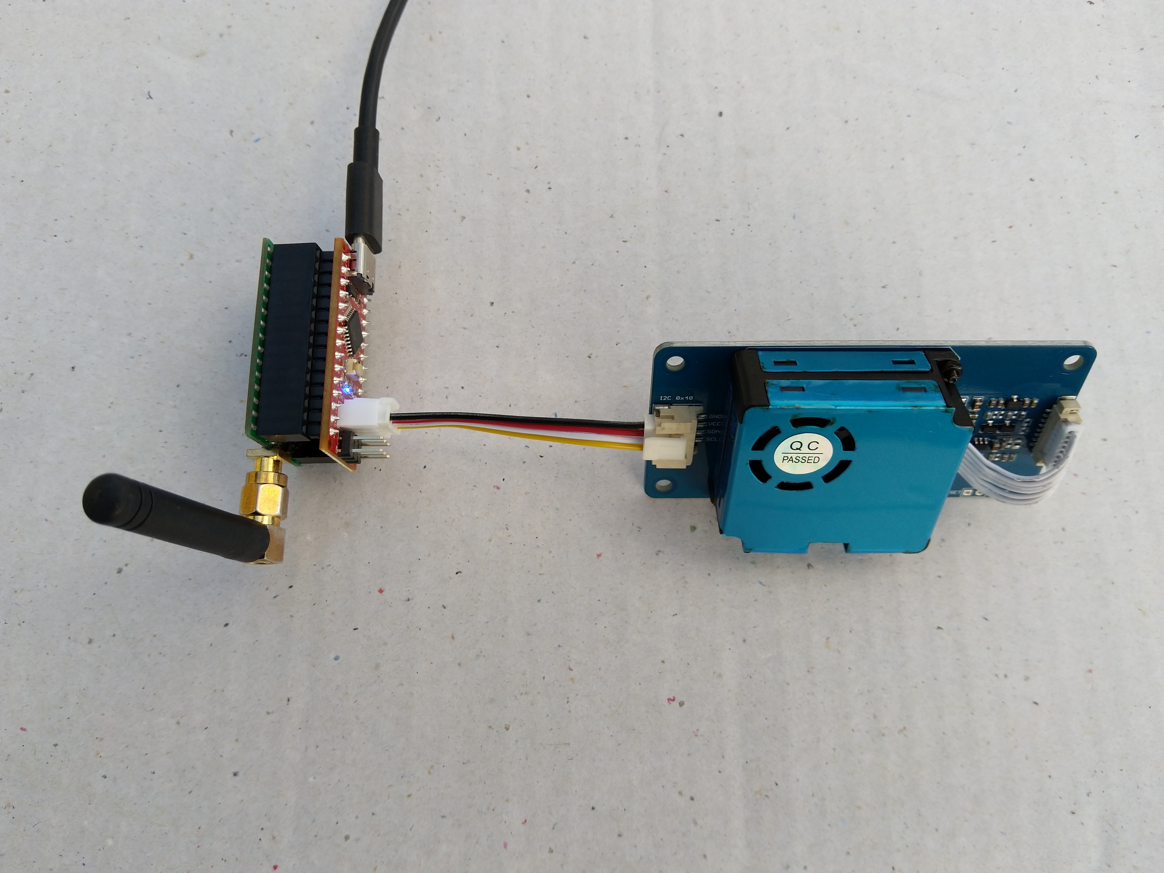
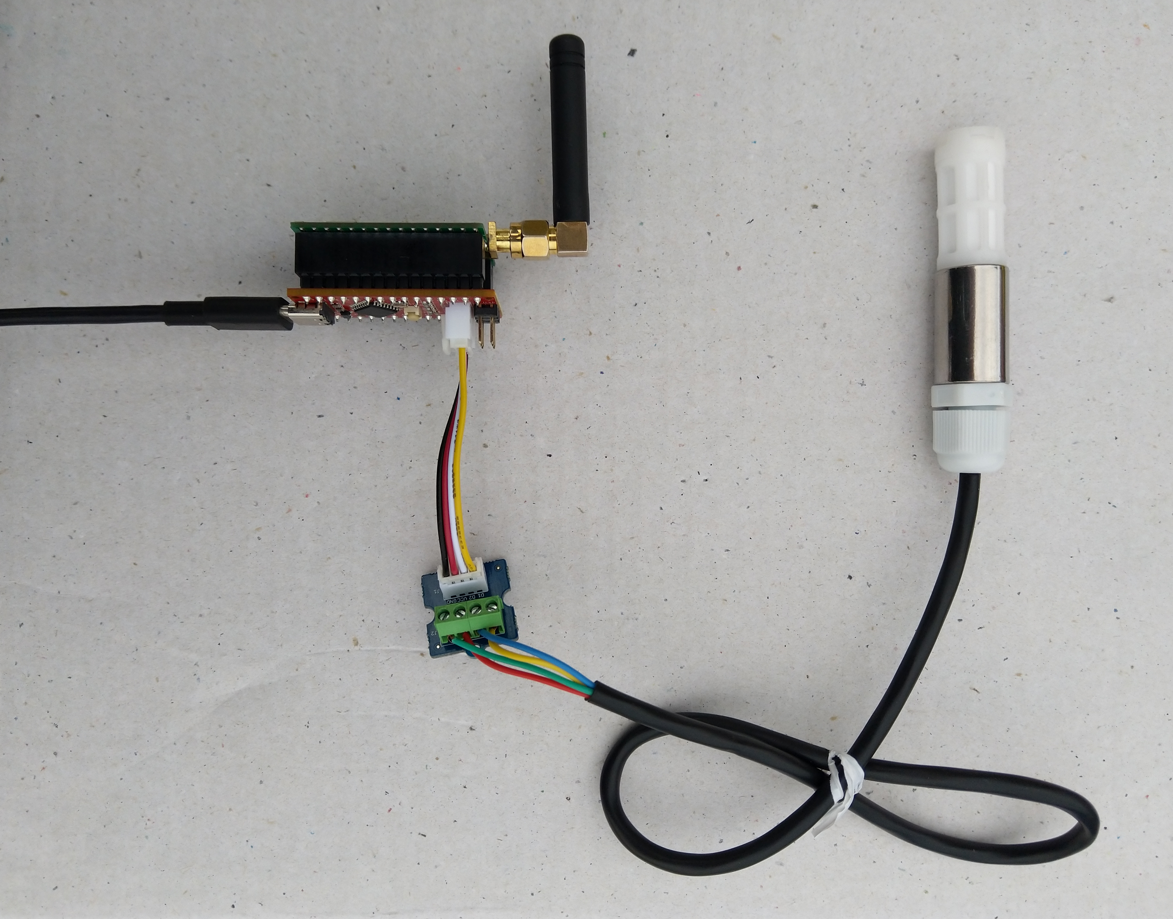
In preparation for a project to build weather stations to place at a couple of local schools I purchased a DF Robot SHT20 Temperature & Humidity Sensor for evaluation.
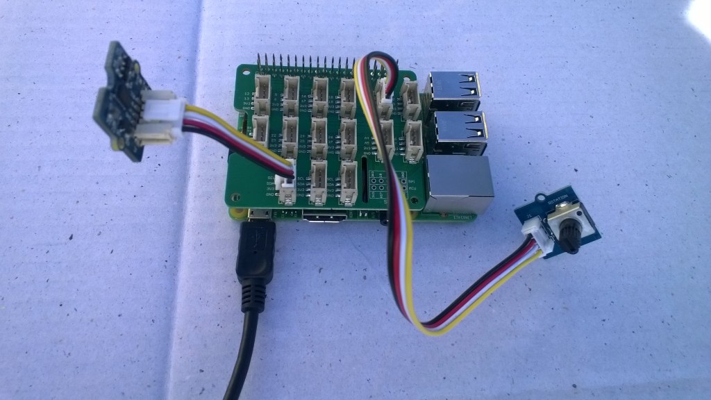
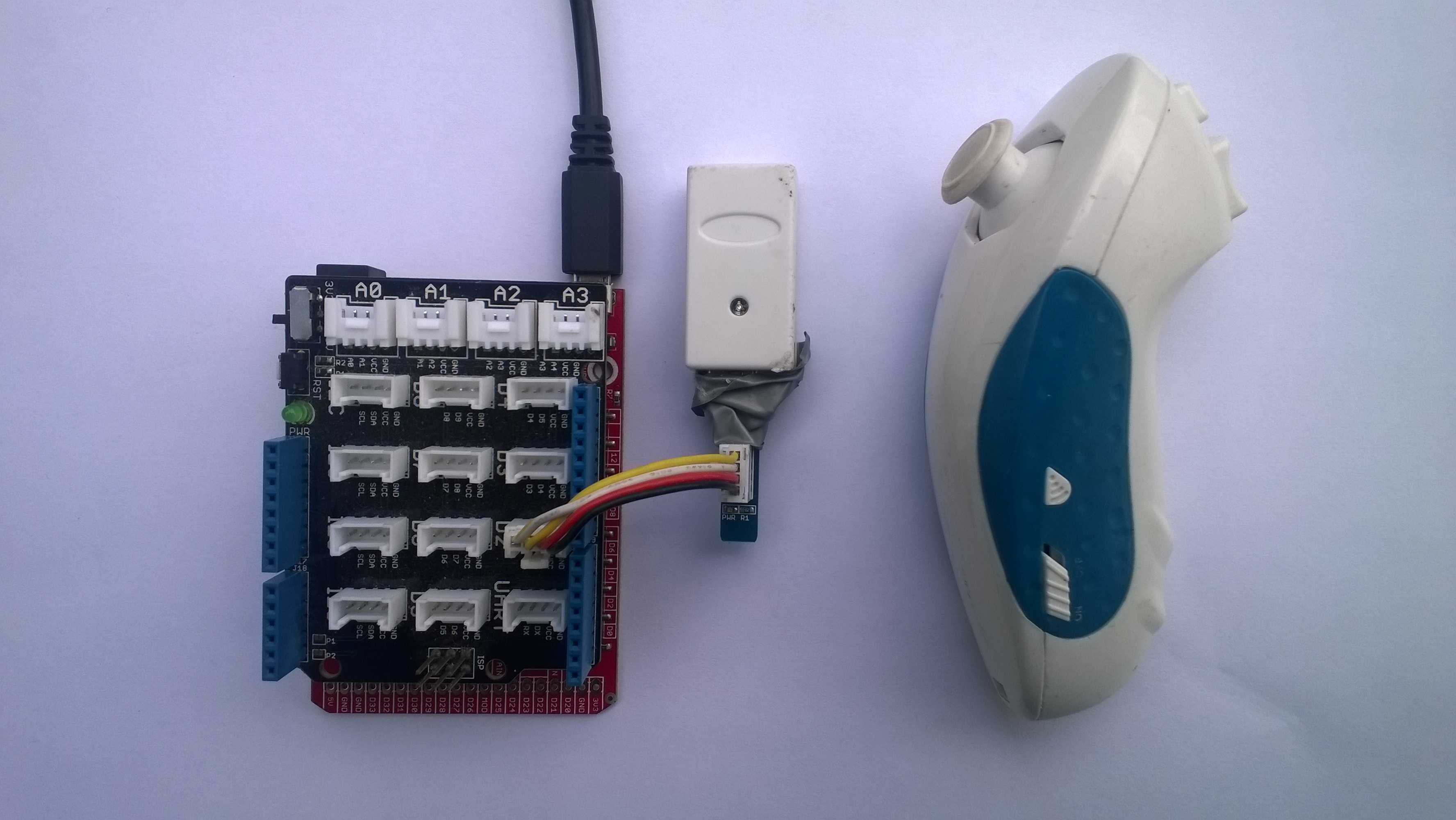
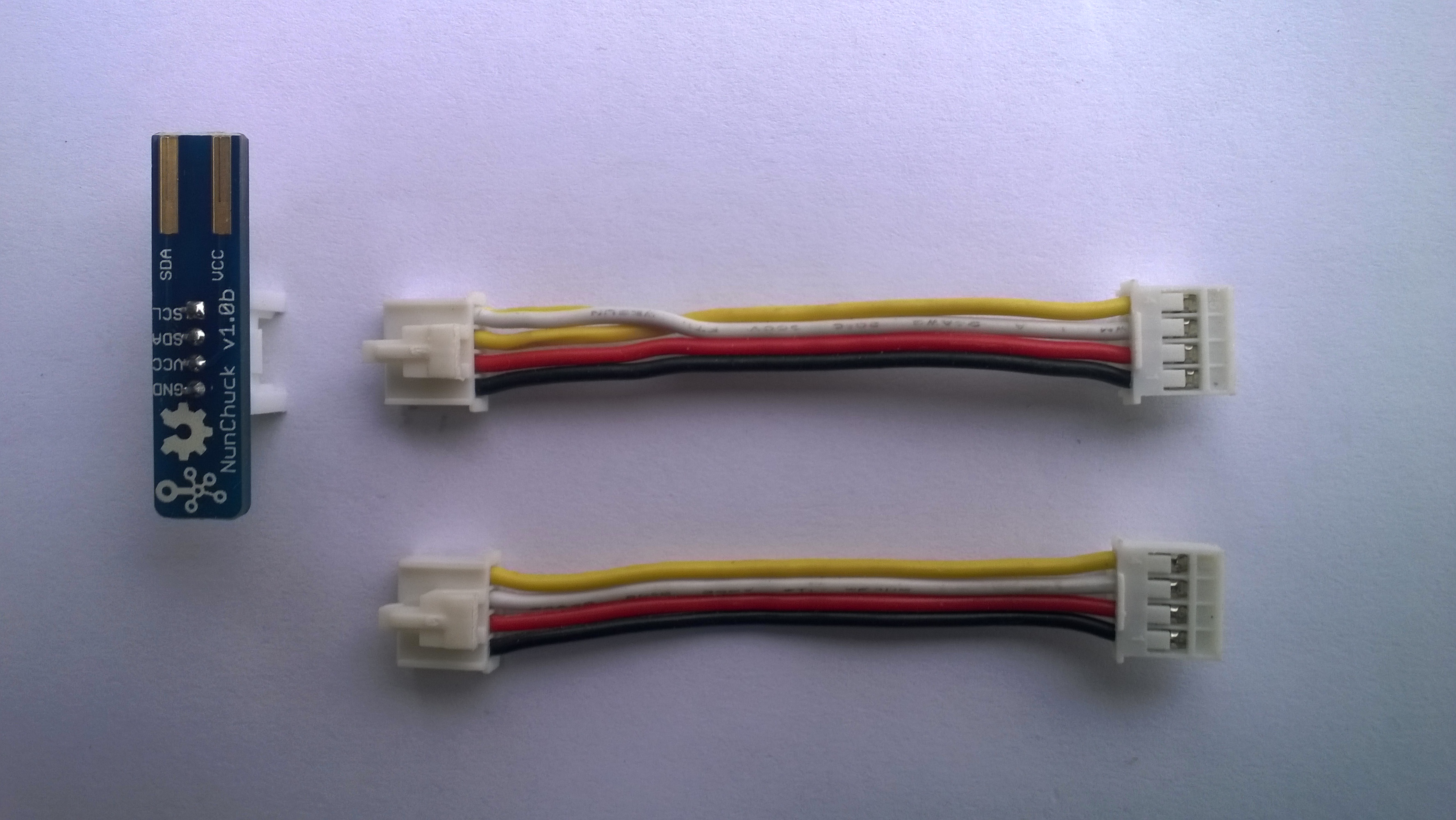
The Seeeduino Nano devices I’m testing have a single on-board I2C socket which meant I didn’t need a Grove Shield for Arduino Nano which reduced the size and cost of the sensor node.
To test my setup I installed the DFRobot Arduino SHT20 library and downloaded a demo application to my device.
I started with my Easy Sensors Arduino Nano Radio Shield RFM69/95 Payload Addressing client and modified it to use the SHT20 sensor.
/*
  Copyright ® 2019 August devMobile Software, All Rights Reserved

  THIS CODE AND INFORMATION IS PROVIDED "AS IS" WITHOUT WARRANTY OF ANY
  KIND, EITHER EXPRESSED OR IMPLIED, INCLUDING BUT NOT LIMITED TO THE
  IMPLIED WARRANTIES OF MERCHANTABILITY AND/OR FITNESS FOR A PARTICULAR
  PURPOSE.

  You can do what you want with this code, acknowledgment would be nice.
  http://www.devmobile.co.nz

  DF Robot SHT20 Temperature & Humidity sensor   https://www.dfrobot.com/wiki/index.php/SHT20_I2C_Temperature_%26_Humidity_Sensor_(Waterproof_Probe)_SKU:_SEN0227

  Seeeduino Nano
  https://www.seeedstudio.com/Seeeduino-Nano-p-4111.html

  Polycarbonate enclosure approx 3.5" x 4.5"
    2 x Cable glands
    1 x ufl to SMA connector
    3M command adhesive strips to hold battery & device in place

*/
#include <stdlib.h>
#include <DFRobot_SHT20.h>
#include <LoRa.h>
#include <sha204_library.h>

//#define DEBUG
//#define DEBUG_TELEMETRY
//#define DEBUG_LORA
//#define DEBUG_TEMPERATURE_AND_HUMIDITY

#define UNITS_HUMIDITY "%"
#define UNITS_TEMPERATURE "°c"

// LoRa field gateway configuration (these settings must match your field gateway)
const byte DeviceAddressMaximumLength = 15 ;
const char FieldGatewayAddress[] = {"LoRaIoT1"};
const float FieldGatewayFrequency =  915000000.0;
const byte FieldGatewaySyncWord = 0x12 ;

// Payload configuration
const int ChipSelectPin = 10;
const int ResetPin = 9;
const int InterruptPin = 2;

// LoRa radio payload configuration
const byte SensorIdValueSeperator = ' ' ;
const byte SensorReadingSeperator = ',' ;
const unsigned long SensorUploadDelay = 60000;

// ATSHA204 secure authentication, validation with crypto and hashing (currently only using for unique serial number)
const byte Atsha204Port = A3;
atsha204Class sha204(Atsha204Port);
const byte DeviceSerialNumberLength = 9 ;
byte deviceSerialNumber[DeviceSerialNumberLength] = {""};

// SHT20 Air temperature and humidity sensor
DFRobot_SHT20 sht20;

const byte PayloadSizeMaximum = 64 ;
byte payload[PayloadSizeMaximum];
byte payloadLength = 0 ;


void setup()
{
  Serial.begin(9600);

#ifdef DEBUG
  while (!Serial);
#endif

  Serial.println("Setup called");

  Serial.print("Field gateway:");
  Serial.print(FieldGatewayAddress ) ;
  Serial.print(" Frequency:");
  Serial.print( FieldGatewayFrequency,0 ) ;
  Serial.print("MHz SyncWord:");
  Serial.print( FieldGatewaySyncWord ) ;
  Serial.println();

   // Retrieve the serial number then display it nicely
  if(sha204.getSerialNumber(deviceSerialNumber))
  {
    Serial.println("sha204.getSerialNumber failed");
    while (true); // Drop into endless loop requiring restart
  }

  Serial.print("SNo:");
  DisplayHex( deviceSerialNumber, DeviceSerialNumberLength);
  Serial.println();

  Serial.println("LoRa setup start");

  // override the default chip select and reset pins
  LoRa.setPins(ChipSelectPin, ResetPin, InterruptPin);
  if (!LoRa.begin(FieldGatewayFrequency))
  {
    Serial.println("LoRa begin failed");
    while (true); // Drop into endless loop requiring restart
  }

  // Need to do this so field gateway pays attention to messsages from this device
  LoRa.enableCrc();
  LoRa.setSyncWord(FieldGatewaySyncWord);

#ifdef DEBUG_LORA
  LoRa.dumpRegisters(Serial);
#endif
  Serial.println("LoRa Setup done.");

  // Configure the DF Robot SHT20, temperature & humidity sensor
  Serial.println("SHT20 setup start");
  sht20.initSHT20();
  delay(100);
  sht20.checkSHT20();
  Serial.println("SHT20 setup done");

  PayloadHeader((byte *)FieldGatewayAddress,strlen(FieldGatewayAddress), deviceSerialNumber, DeviceSerialNumberLength);

  Serial.println("Setup done");
  Serial.println();
}


void loop()
{
  unsigned long currentMilliseconds = millis();
  float temperature ;
  float humidity ;

  Serial.println("Loop called");

  PayloadReset();

  humidity = sht20.readHumidity();
  PayloadAdd( "h", humidity, 0, false);

  temperature = sht20.readTemperature();
  PayloadAdd( "t", temperature, 1, false);

  #ifdef DEBUG_TEMPERATURE_AND_HUMIDITY
    Serial.print("H:");
    Serial.print( humidity, 0 ) ;
    Serial.print( UNITS_HUMIDITY ) ;
    Serial.print("T:");
    Serial.print( temperature, 1 ) ;
    Serial.println( UNITS_TEMPERATURE ) ;
  #endif

  #ifdef DEBUG_TELEMETRY
    Serial.println();
    Serial.print("RFM9X/SX127X Payload length:");
    Serial.print(payloadLength);
    Serial.println(" bytes");
  #endif

  LoRa.beginPacket();
  LoRa.write(payload, payloadLength);
  LoRa.endPacket();

  Serial.println("Loop done");
  Serial.println();

  delay(SensorUploadDelay - (millis() - currentMilliseconds ));
}


void PayloadHeader( const byte *to, byte toAddressLength, const byte *from, byte fromAddressLength)
{
  byte addressesLength = toAddressLength + fromAddressLength ;

  payloadLength = 0 ;

  // prepare the payload header with "To" Address length (top nibble) and "From" address length (bottom nibble)

  payload[payloadLength] = (toAddressLength << 4) | fromAddressLength ;
  payloadLength += 1;

  // Copy the "To" address into payload
  memcpy(&payload[payloadLength], to, toAddressLength);
  payloadLength += toAddressLength ;

  // Copy the "From" into payload
  memcpy(&payload[payloadLength], from, fromAddressLength);
  payloadLength += fromAddressLength ;
}


void PayloadAdd( const char *sensorId, float value, byte decimalPlaces, bool last)
{
  byte sensorIdLength = strlen( sensorId ) ;

  memcpy( &payload[payloadLength], sensorId,  sensorIdLength) ;
  payloadLength += sensorIdLength ;
  payload[ payloadLength] = SensorIdValueSeperator;
  payloadLength += 1 ;
  payloadLength += strlen( dtostrf(value, -1, decimalPlaces, (char *)&payload[payloadLength]));
  if (!last)
  {
    payload[ payloadLength] = SensorReadingSeperator;
    payloadLength += 1 ;
  }

#ifdef DEBUG_TELEMETRY
  Serial.print("PayloadAdd float-payloadLength:");
  Serial.print( payloadLength);
  Serial.println( );
#endif
}


void PayloadAdd( char *sensorId, int value, bool last )
{
  byte sensorIdLength = strlen(sensorId) ;

  memcpy(&payload[payloadLength], sensorId,  sensorIdLength) ;
  payloadLength += sensorIdLength ;
  payload[ payloadLength] = SensorIdValueSeperator;
  payloadLength += 1 ;
  payloadLength += strlen(itoa( value,(char *)&payload[payloadLength],10));
  if (!last)
  {
    payload[ payloadLength] = SensorReadingSeperator;
    payloadLength += 1 ;
  }

#ifdef DEBUG_TELEMETRY
  Serial.print("PayloadAdd int-payloadLength:" );
  Serial.print(payloadLength);
  Serial.println( );
#endif
}


void PayloadAdd( char *sensorId, unsigned int value, bool last )
{
  byte sensorIdLength = strlen(sensorId) ;

  memcpy(&payload[payloadLength], sensorId,  sensorIdLength) ;
  payloadLength += sensorIdLength ;
  payload[ payloadLength] = SensorIdValueSeperator;
  payloadLength += 1 ;
  payloadLength += strlen(utoa( value,(char *)&payload[payloadLength],10));
  if (!last)
  {
    payload[ payloadLength] = SensorReadingSeperator;
    payloadLength += 1 ;
  }

#ifdef DEBUG_TELEMETRY
  Serial.print("PayloadAdd uint-payloadLength:");
  Serial.print(payloadLength);
  Serial.println( );
#endif
}


void PayloadReset()
{
  byte fromAddressLength = payload[0] & 0xf ;
  byte toAddressLength = payload[0] >> 4 ;

  payloadLength = toAddressLength + fromAddressLength + 1;
}


void DisplayHex( byte *byteArray, byte length)
{
  for (int i = 0; i < length ; i++)
  {
    // Add a leading zero
    if ( byteArray[i] < 16)
    {
      Serial.print("0");
    }
    Serial.print(byteArray[i], HEX);
    if ( i < (length-1)) // Don't put a - after last digit
    {
      Serial.print("-");
    }
  }
}
The code is available on GitHub.
20:52:09.656 -> Setup called
20:52:09.690 -> Field gateway:LoRaIoT1 Frequency:915000000MHz SyncWord:18
20:52:09.794 -> SNo:01-23-21-61-D6-D1-F5-86-EE
20:52:09.828 -> LoRa setup start
20:52:09.828 -> LoRa Setup done.
20:52:09.862 -> SHT20 setup start
20:52:09.932 -> End of battery: no
20:52:09.932 -> Heater enabled: no
20:52:09.965 -> Disable OTP reload: yes
20:52:09.999 -> SHT20 setup done
20:52:09.999 -> Setup done
20:52:09.999 ->
20:52:09.999 -> Loop called
20:52:10.067 -> H:60%T:20.0°c
20:52:10.136 -> Loop done
20:52:10.136 ->
20:53:09.915 -> Loop called
20:53:10.019 -> H:61%T:20.5°c
20:53:10.088 -> Loop done
20:53:10.088 ->
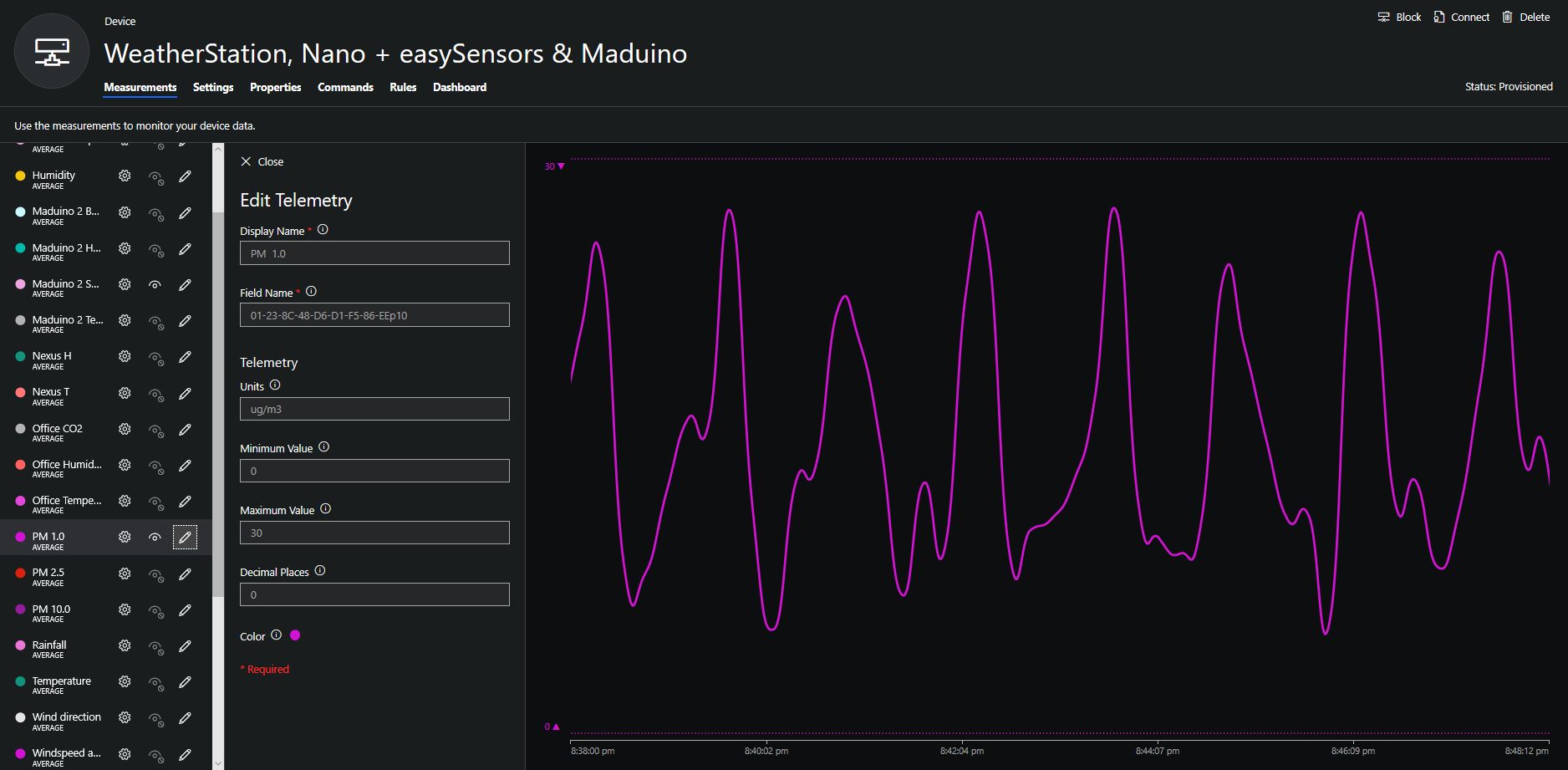
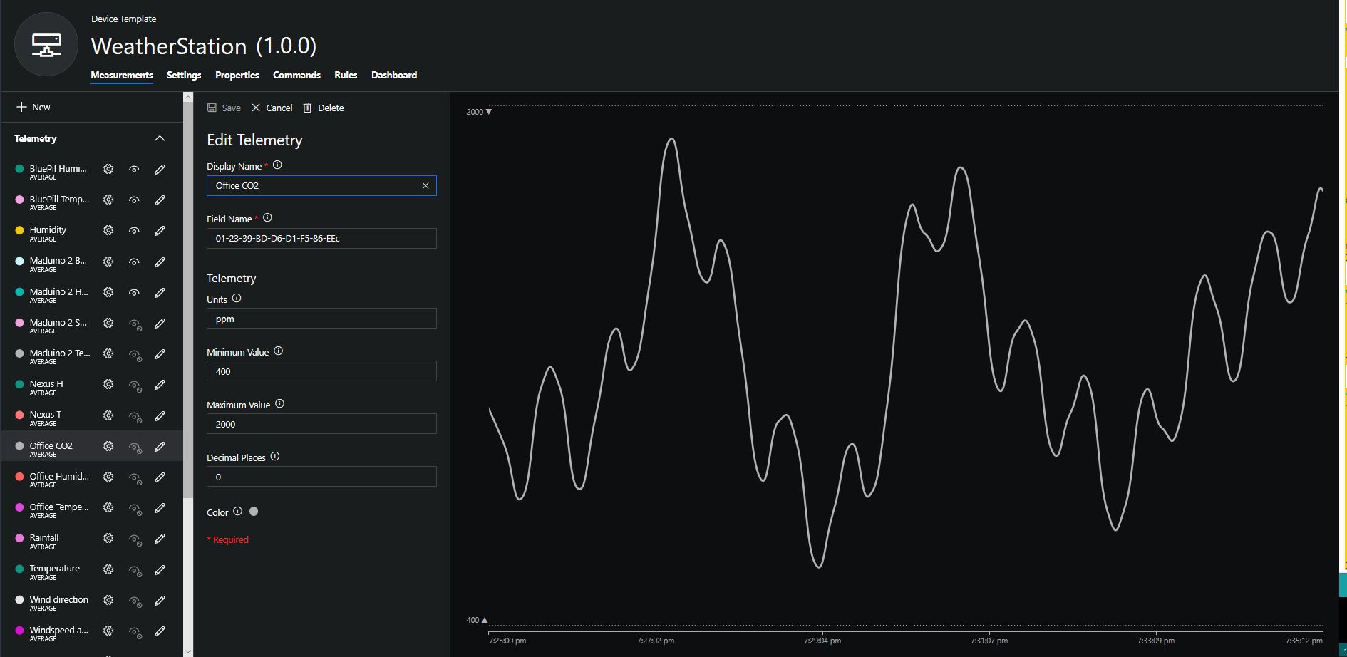
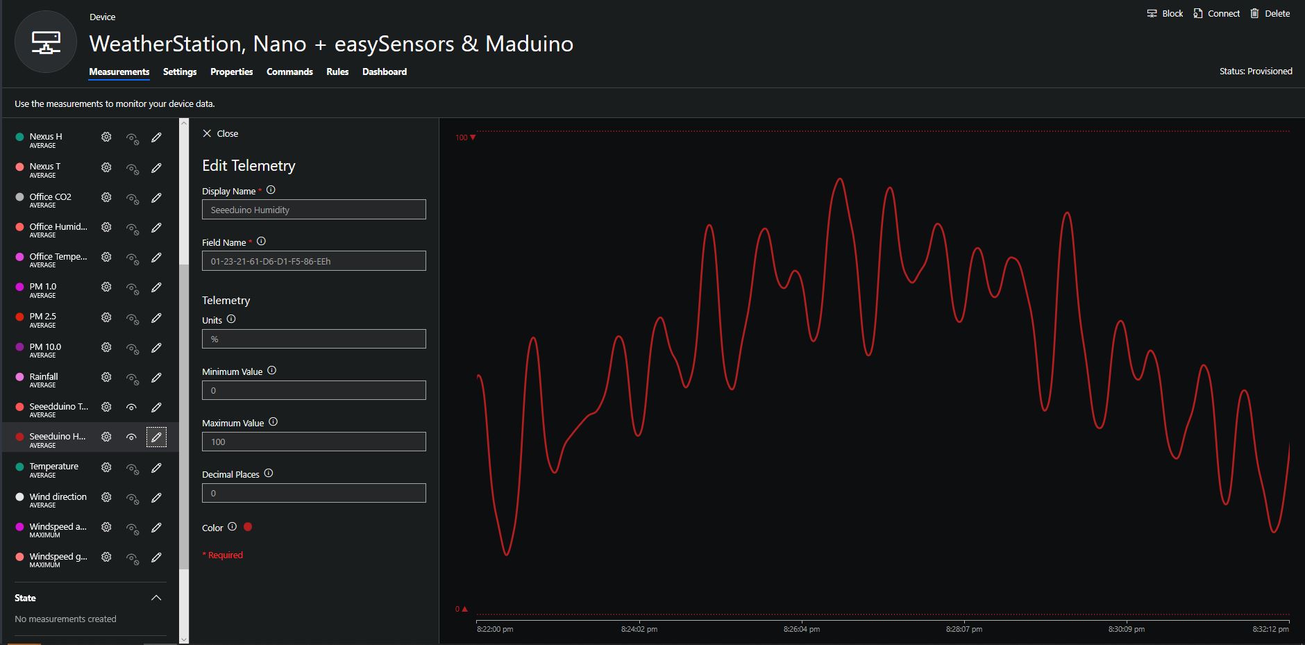
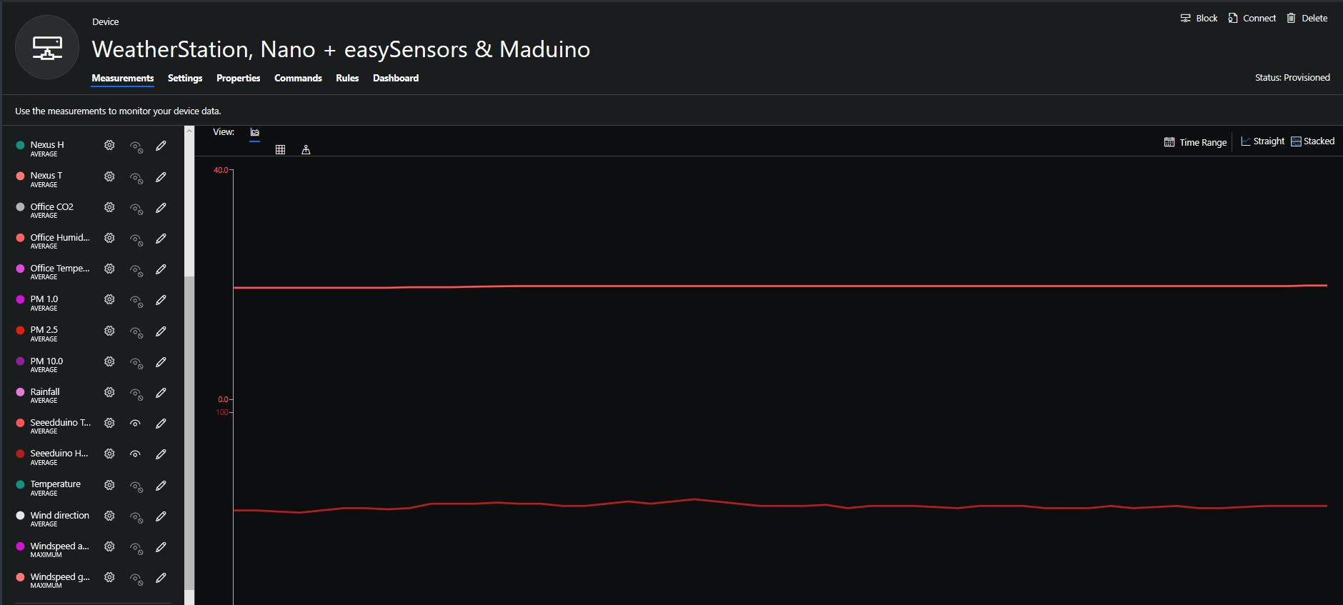
To configure the device in Azure IoT Central (similar process for Adafruit.IO, working on support for losant,and ubidots I copied the SNo: from the Arduino development tool logging window and appended p10 for PM 1 value, p25 for PM2.5 value and p100 for PM10 value to the unique serial number from the ATSHA204A chip. (N.B. pay attention to the case of the field names they are case sensitive)
When I moved the sensor indoors it appeared to take a while to warm up and after a while the metal body still felt cold. The sensor element is surrounded by quite a bit of protective packaging for outdoors use and I that would have a bit more thermal inertia the than the lightweight indoor enclosure.
It would be good to run the sensor alongside a calibrated temperature & humidity sensor to see how accurate and responsive it is.
Bill of materials (prices as at August 2019)