Encryption: Rasmatic/RFM69-Arduino-Library
The RFM69CW/RFM69HCW modules (based on the Semtech SX1231/SX1231H) have built in support for AES128 encryption. In this test harness I’m exploring the RFM69 AES128 implementation.
In the Arduino code I found the order of initialisation was critical. Because of the way the Rasmatic library is written the call to vRF69SetAesKey has to be after the vInitialize.
void setup()
{
  Serial.begin(9600);

  pinMode(SENDER_DETECT_PIN, INPUT_PULLUP);

  radio.Modulation     = FSK;
  radio.COB            = RFM69;
  radio.Frequency      = 915000;
  radio.OutputPower    = 10+18;          //10dBm OutputPower
  radio.PreambleLength = 16;             //16Byte preamble
  radio.FixedPktLength = false;          //packet in message which need to be send
  radio.CrcDisable     = false;          //CRC On
  radio.AesOn          = false;
  radio.SymbolTime     = 416000;         //2.4Kbps
  radio.Devation       = 35;             //35KHz for devation
  radio.BandWidth      = 100;            //100KHz for bandwidth
  radio.SyncLength     = 3;              //
  radio.SyncWord[0]    = 0xAA;
  radio.SyncWord[1]    = 0x2D;
  radio.SyncWord[2]    = 0xD4;

  // Highly secure 16byte fixed length key
  radio.AesKey[0] = 0x0;
  radio.AesKey[1] = 0x1;
  radio.AesKey[2] = 0x2;
  radio.AesKey[3] = 0x3;
  radio.AesKey[4] = 0x4;
  radio.AesKey[5] = 0x5;
  radio.AesKey[6] = 0x6;
  radio.AesKey[7] = 0x7;
  radio.AesKey[8] = 0x8;
  radio.AesKey[9] = 0x9;
  radio.AesKey[10] = 0xA;
  radio.AesKey[11] = 0xB;
  radio.AesKey[12] = 0xC;
  radio.AesKey[13] = 0xD;
  radio.AesKey[14] = 0xE;
  radio.AesKey[15] = 0xF;
  radio.AesOn = true ;

  radio.vInitialize();

  radio.vRF69SetAesKey();
When I first fired up the Arduino client on the Windows 10 IoT Core device I hadn’t configured the AES key but had enabled encryption.
19:21:25 Received 13 byte message =!{��>�_��5
19:21:26.114 RegIrqFlags 01000110
19:21:26 Received 13 byte message ���gǺm,0|��
19:21:26.273 Send-Done
19:21:26.453 RegIrqFlags 00001000
19:21:26.467 Transmit-Done
19:21:27.244 RegIrqFlags 01000110
19:21:27 Received 13 byte message w6�H�Y���#"#
19:21:28.373 RegIrqFlags 01000110
19:21:28 Received 13 byte message c�u�$mԙ���M{
...
Restart Arduino client
...
19:21:34.836 RegIrqFlags 01000110
19:21:34 Received 13 byte message ���gǺm,0|��
19:21:35.965 RegIrqFlags 01000110
19:21:35 Received 13 byte message w6�H�Y���#"#
19:21:36.429 Send-Done
19:21:36.610 RegIrqFlags 00001000
19:21:36.624 Transmit-Done
19:21:37.095 RegIrqFlags 01000110
19:21:37 Received 13 byte message c�u�$mԙ���M{
The program '[1560] backgroundTaskHost.exe' has exited with code -1 (0xffffffff).
When I restarted the Arduino client I got the same sequences of characters in the messages so it looks like the RFM69 encryption is most probably using electronic code book (ECB) rather than a mode with a changing initialisation vector(IV) e.g. cypher block chaining(CBC). (which wasn’t a surprise)
After modifying the Windows 10 IoT Core application to receive and transmit encrypted payloads
/*
Copyright ® 2019 July devMobile Software, All Rights Reserved
MIT License
Permission is hereby granted, free of charge, to any person obtaining a copy
of this software and associated documentation files (the "Software"), to deal
in the Software without restriction, including without limitation the rights
to use, copy, modify, merge, publish, distribute, sublicense, and/or sell
copies of the Software, and to permit persons to whom the Software is
furnished to do so, subject to the following conditions:
The above copyright notice and this permission notice shall be included in all
copies or substantial portions of the Software.
THE SOFTWARE IS PROVIDED "AS IS", WITHOUT WARRANTY OF ANY KIND, EXPRESS OR
IMPLIED, INCLUDING BUT NOT LIMITED TO THE WARRANTIES OF MERCHANTABILITY,
FITNESS FOR A PARTICULAR PURPOSE AND NONINFRINGEMENT. IN NO EVENT SHALL THE
AUTHORS OR COPYRIGHT HOLDERS BE LIABLE FOR ANY CLAIM, DAMAGES OR OTHER
LIABILITY, WHETHER IN AN ACTION OF CONTRACT, TORT OR OTHERWISE, ARISING FROM,
OUT OF OR IN CONNECTION WITH THE SOFTWARE OR THE USE OR OTHER DEALINGS IN THE
SOFTWARE
*/
namespace devMobile.IoT.Rfm69Hcw.Encryption
{
using System;
using System.Diagnostics;
using System.Runtime.InteropServices.WindowsRuntime;
using System.Text;
using System.Threading.Tasks;
using Windows.ApplicationModel.Background;
using Windows.Devices.Gpio;
using Windows.Devices.Spi;
public sealed class Rfm69HcwDevice
{
private SpiDevice Rfm69Hcw;
private GpioPin InterruptGpioPin = null;
private const byte RegisterAddressReadMask = 0X7f;
private const byte RegisterAddressWriteMask = 0x80;
public Rfm69HcwDevice(int chipSelectPin, int resetPin, int interruptPin)
{
SpiController spiController = SpiController.GetDefaultAsync().AsTask().GetAwaiter().GetResult();
var settings = new SpiConnectionSettings(chipSelectPin)
{
ClockFrequency = 500000,
Mode = SpiMode.Mode0,
};
// Factory reset pin configuration
GpioController gpioController = GpioController.GetDefault();
GpioPin resetGpioPin = gpioController.OpenPin(resetPin);
resetGpioPin.SetDriveMode(GpioPinDriveMode.Output);
resetGpioPin.Write(GpioPinValue.High);
Task.Delay(100);
resetGpioPin.Write(GpioPinValue.Low);
Task.Delay(10);
// Interrupt pin for RX message & TX done notification
InterruptGpioPin = gpioController.OpenPin(interruptPin);
resetGpioPin.SetDriveMode(GpioPinDriveMode.Input);
InterruptGpioPin.ValueChanged += InterruptGpioPin_ValueChanged;
Rfm69Hcw = spiController.GetDevice(settings);
}
private void InterruptGpioPin_ValueChanged(GpioPin sender, GpioPinValueChangedEventArgs args)
{
if (args.Edge != GpioPinEdge.RisingEdge)
{
return;
}
byte irqFlags = this.RegisterReadByte(0x28); // RegIrqFlags2
Debug.WriteLine("{0:HH:mm:ss.fff} RegIrqFlags {1}", DateTime.Now, Convert.ToString((byte)irqFlags, 2).PadLeft(8, '0'));
if ((irqFlags & 0b00000100) == 0b00000100) // PayLoadReady set
{
// Read the length of the buffer
byte numberOfBytes = this.RegisterReadByte(0x0);
// Allocate buffer for message
byte[] messageBytes = new byte[numberOfBytes];
for (int i = 0; i < numberOfBytes; i++)
{
messageBytes[i] = this.RegisterReadByte(0x00); // RegFifo
}
string messageText = UTF8Encoding.UTF8.GetString(messageBytes);
Debug.WriteLine("{0:HH:mm:ss} Received {1} byte message {2}", DateTime.Now, messageBytes.Length, messageText);
}
if ((irqFlags & 0b00001000) == 0b00001000) // PacketSent set
{
this.RegisterWriteByte(0x01, 0b00010000); // RegOpMode set ReceiveMode
Debug.WriteLine("{0:HH:mm:ss.fff} Transmit-Done", DateTime.Now);
}
}
public Byte RegisterReadByte(byte address)
{
byte[] writeBuffer = new byte[] { address &= RegisterAddressReadMask };
byte[] readBuffer = new byte[1];
Debug.Assert(Rfm69Hcw != null);
Rfm69Hcw.TransferSequential(writeBuffer, readBuffer);
return readBuffer[0];
}
public byte[] RegisterRead(byte address, int length)
{
byte[] writeBuffer = new byte[] { address &= RegisterAddressReadMask };
byte[] readBuffer = new byte[length];
Debug.Assert(Rfm69Hcw != null);
Rfm69Hcw.TransferSequential(writeBuffer, readBuffer);
return readBuffer;
}
public void RegisterWriteByte(byte address, byte value)
{
byte[] writeBuffer = new byte[] { address |= RegisterAddressWriteMask, value };
Debug.Assert(Rfm69Hcw != null);
Rfm69Hcw.Write(writeBuffer);
}
public void RegisterWrite(byte address, [ReadOnlyArray()] byte[] bytes)
{
byte[] writeBuffer = new byte[1 + bytes.Length];
Debug.Assert(Rfm69Hcw != null);
Array.Copy(bytes, 0, writeBuffer, 1, bytes.Length);
writeBuffer[0] = address |= RegisterAddressWriteMask;
Rfm69Hcw.Write(writeBuffer);
}
public void RegisterDump()
{
Debug.WriteLine("Register dump");
for (byte registerIndex = 0; registerIndex <= 0x3D; registerIndex++)
{
byte registerValue = this.RegisterReadByte(registerIndex);
Debug.WriteLine("Register 0x{0:x2} - Value 0X{1:x2} - Bits {2}", registerIndex, registerValue, Convert.ToString(registerValue, 2).PadLeft(8, '0'));
}
}
}
public sealed class StartupTask : IBackgroundTask
{
private const int ChipSelectLine = 1;
private const int ResetPin = 25;
private const int InterruptPin = 22;
private Rfm69HcwDevice rfm69Device = new Rfm69HcwDevice(ChipSelectLine, ResetPin, InterruptPin);
const double RH_RF6M9HCW_FXOSC = 32000000.0;
const double RH_RFM69HCW_FSTEP = RH_RF6M9HCW_FXOSC / 524288.0;
public void Run(IBackgroundTaskInstance taskInstance)
{
//rfm69Device.RegisterDump();
// regOpMode standby
rfm69Device.RegisterWriteByte(0x01, 0b00000100);
// BitRate MSB/LSB
rfm69Device.RegisterWriteByte(0x03, 0x34);
rfm69Device.RegisterWriteByte(0x04, 0x00);
// Frequency deviation
rfm69Device.RegisterWriteByte(0x05, 0x02);
rfm69Device.RegisterWriteByte(0x06, 0x3d);
// Calculate the frequency accoring to the datasheett
byte[] bytes = BitConverter.GetBytes((uint)(915000000.0 / RH_RFM69HCW_FSTEP));
Debug.WriteLine("Byte Hex 0x{0:x2} 0x{1:x2} 0x{2:x2} 0x{3:x2}", bytes[0], bytes[1], bytes[2], bytes[3]);
rfm69Device.RegisterWriteByte(0x07, bytes[2]);
rfm69Device.RegisterWriteByte(0x08, bytes[1]);
rfm69Device.RegisterWriteByte(0x09, bytes[0]);
// RegRxBW
rfm69Device.RegisterWriteByte(0x19, 0x2a);
// RegDioMapping1
rfm69Device.RegisterWriteByte(0x26, 0x01);
// Setup preamble length to 16 (default is 3) RegPreambleMsb RegPreambleLsb
rfm69Device.RegisterWriteByte(0x2C, 0x0);
rfm69Device.RegisterWriteByte(0x2D, 0x10);
// RegSyncConfig Set the Sync length and byte values SyncOn + 3 custom sync bytes
rfm69Device.RegisterWriteByte(0x2e, 0x90);
// RegSyncValues1 thru RegSyncValues3
rfm69Device.RegisterWriteByte(0x2f, 0xAA);
rfm69Device.RegisterWriteByte(0x30, 0x2D);
rfm69Device.RegisterWriteByte(0x31, 0xD4);
// RegPacketConfig1 Variable length with CRC on
rfm69Device.RegisterWriteByte(0x37, 0x90);
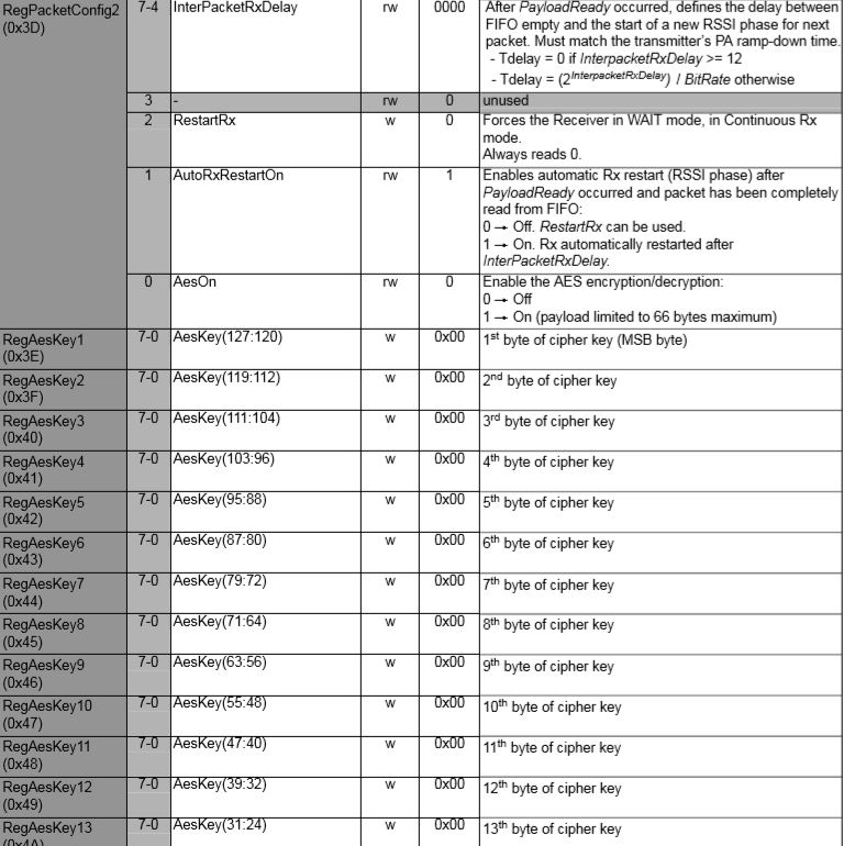
// Set the AES key and turn on AES RegPacketConfig2
rfm69Device.RegisterWriteByte(0x3D, 0x03);
rfm69Device.RegisterWriteByte(0x3E, 0x00);
rfm69Device.RegisterWriteByte(0x3F, 0x01);
rfm69Device.RegisterWriteByte(0x40, 0x02);
rfm69Device.RegisterWriteByte(0x41, 0x03);
rfm69Device.RegisterWriteByte(0x42, 0x04);
rfm69Device.RegisterWriteByte(0x43, 0x05);
rfm69Device.RegisterWriteByte(0x44, 0x06);
rfm69Device.RegisterWriteByte(0x45, 0x07);
rfm69Device.RegisterWriteByte(0x46, 0x08);
rfm69Device.RegisterWriteByte(0x47, 0x09);
rfm69Device.RegisterWriteByte(0x48, 0x0A);
rfm69Device.RegisterWriteByte(0x49, 0x0B);
rfm69Device.RegisterWriteByte(0x4A, 0x0C);
rfm69Device.RegisterWriteByte(0x4B, 0x0D);
rfm69Device.RegisterWriteByte(0x4C, 0x0E);
rfm69Device.RegisterWriteByte(0x4D, 0x0F);
/*
// Clear out the AES key
rfm69Device.RegisterWriteByte(0x3E, 0x0);
rfm69Device.RegisterWriteByte(0x3F, 0x0);
rfm69Device.RegisterWriteByte(0x40, 0x0);
rfm69Device.RegisterWriteByte(0x41, 0x0);
rfm69Device.RegisterWriteByte(0x42, 0x0);
rfm69Device.RegisterWriteByte(0x43, 0x0);
rfm69Device.RegisterWriteByte(0x44, 0x0);
rfm69Device.RegisterWriteByte(0x45, 0x0);
rfm69Device.RegisterWriteByte(0x46, 0x0);
rfm69Device.RegisterWriteByte(0x47, 0x0);
rfm69Device.RegisterWriteByte(0x48, 0x0);
rfm69Device.RegisterWriteByte(0x49, 0x0);
rfm69Device.RegisterWriteByte(0x4A, 0x0);
rfm69Device.RegisterWriteByte(0x4B, 0x0);
rfm69Device.RegisterWriteByte(0x4C, 0x0);
rfm69Device.RegisterWriteByte(0x4D, 0x0);
*/
rfm69Device.RegisterDump();
while (true)
{
// Standby mode while loading message into FIFO
rfm69Device.RegisterWriteByte(0x01, 0b00000100);
byte[] messageBuffer = UTF8Encoding.UTF8.GetBytes("hello world " + DateTime.Now.ToLongTimeString());
rfm69Device.RegisterWriteByte(0x0, (byte)messageBuffer.Length);
rfm69Device.RegisterWrite(0x0, messageBuffer);
// Transmit mode once FIFO loaded
rfm69Device.RegisterWriteByte(0x01, 0b00001100);
Debug.WriteLine("{0:HH:mm:ss.fff} Send-Done", DateTime.Now);
Task.Delay(5000).Wait();
}
}
}
}
I could see inbound messages from the transmit Arduino and Windows 10 device interleaved on the receive Arduino.
21:06:12.735 -> RX start
21:06:12.735 -> 0x0: 0x0
21:06:12.769 -> 0x1: 0x10
21:06:12.769 -> 0x2: 0x0
…
21:06:13.453 -> 0x3B: 0x0
21:06:13.453 -> 0x3C: 0x1
21:06:13.487 -> 0x3D: 0x1
21:06:15.218 -> MessageIn:hello world 9:06:15 PM
21:06:20.317 -> MessageIn:hello world 9:06:20 PM
21:06:24.559 -> MessageIn:Hello world:0
21:06:25.384 -> MessageIn:hello world 9:06:25 PM
21:06:28.009 -> MessageIn:Hello world:1
21:06:30.454 -> MessageIn:hello world 9:06:30 PM
21:06:31.455 -> MessageIn:Hello world:2
21:06:34.939 -> MessageIn:Hello world:3
21:06:35.596 -> MessageIn:hello world 9:06:35 PM
21:06:38.389 -> MessageIn:Hello world:4
21:06:40.666 -> MessageIn:hello world 9:06:40 PM
21:06:41.838 -> MessageIn:Hello world:5
21:06:45.316 -> MessageIn:Hello world:6
21:06:45.731 -> MessageIn:hello world 9:06:45 PM
21:06:48.761 -> MessageIn:Hello world:7
21:06:50.799 -> MessageIn:hello world 9:06:50 PM
21:06:52.214 -> MessageIn:Hello world:8
The next step will be merging and refactoring the test harness to extract the code for accessing the RFM69 registers into a separate class, then defining enumerations and constants for all the RFM69 settings.
