All the previous versions of my .NET nanoFramework Semtech SX127X (LoRa® Mode) library only supported a Dio0 (RegDioMapping1 bits 6&7) EventHandler. This version supports mapping Dio0, Dio1, Dio2, Dio3, Dio4 and Dio5.
The Dragino Arduino Shield featuring LoRa® technology does not have Dio3 and Dio4 connected so I have been unable to test that functionality.

The SX127XLoRaDeviceClient main now has OnRxTimeout, OnReceive, OnPayloadCrcError, OnValidHeader, OnTransmit, OnChannelActivityDetectionDone, OnFhssChangeChannel, and OnChannelActivityDetected event handlers (Based on RegIrqFlags bit ordering)
static void Main(string[] args)
{
	int sendCount = 0;
...
#if NETDUINO3_WIFI
	// Arduino D10->PB10
	int chipSelectLine = PinNumber('B', 10);
	// Arduino D9->PE5
	int resetPinNumber = PinNumber('E', 5);
	// Arduino D2 -PA3
	int dio0PinNumber = PinNumber('A', 3);
	// Arduino D6 - PB9
	int dio1PinNumber = PinNumber('B', 9);
	// Arduino D7
	int dio2PinNumber = PinNumber('A', 1);
	// Not connected on Dragino LoRa shield
	//int dio3PinNumber = PinNumber('A', 1);
	//  Not connected on Dragino LoRa shield
	//int dio4PinNumber = PinNumber('A', 1);
	// Arduino D8
	int dio5PinNumber = PinNumber('A', 0);
#endif
...
	Console.WriteLine("devMobile.IoT.SX127xLoRaDevice Client starting");

	try
	{
		var settings = new SpiConnectionSettings(SpiBusId, chipSelectLine)
		{
			ClockFrequency = 1000000,
			Mode = SpiMode.Mode0,// From SemTech docs pg 80 CPOL=0, CPHA=0
			SharingMode = SpiSharingMode.Shared
		};

		using (SpiDevice spiDevice = new SpiDevice(settings))
		using (GpioController gpioController = new GpioController())
		{
...
#if NETDUINO3_WIFI || ST_STM32F769I_DISCOVERY
			sx127XDevice = new SX127XDevice(spiDevice, gpioController, dio0Pin:dio0PinNumber, resetPin:resetPinNumber, dio1Pin: dio1PinNumber, dio2Pin: dio2PinNumber);
#endif

			sx127XDevice.Initialise(Frequency
						, lnaGain: Configuration.RegLnaLnaGain.Default
						, lnaBoost: true
						, powerAmplifier: Configuration.RegPAConfigPASelect.PABoost
						, rxPayloadCrcOn: true
						, rxDoneignoreIfCrcMissing: false
						);

#if DEBUG
			sx127XDevice.RegisterDump();
#endif

			//sx127XDevice.OnRxTimeout += Sx127XDevice_OnRxTimeout;
			sx127XDevice.OnReceive += SX127XDevice_OnReceive;
			//sx127XDevice.OnPayloadCrcError += Sx127XDevice_OnPayloadCrcError;
			//sx127XDevice.OnValidHeader += Sx127XDevice_OnValidHeader;
			sx127XDevice.OnTransmit += SX127XDevice_OnTransmit;
			//sx127XDevice.OnChannelActivityDetectionDone += Sx127XDevice_OnChannelActivityDetectionDone;
			//sx127XDevice.OnFhssChangeChannel += Sx127XDevice_OnFhssChangeChannel;
			//sx127XDevice.OnChannelActivityDetected += SX127XDevice_OnChannelActivityDetected;

			sx127XDevice.Receive();
			//sx127XDevice.ChannelActivityDetect();

			Thread.Sleep(500);

			while (true)
			{
				string messageText = $"Hello LoRa from .NET nanoFramework Count {sendCount+=1}!";

				byte[] messageBytes = UTF8Encoding.UTF8.GetBytes(messageText);
				Console.WriteLine($"{DateTime.UtcNow:HH:mm:ss}-TX {messageBytes.Length} byte message {messageText}");
				sx127XDevice.Send(messageBytes);

				Thread.Sleep(50000);

				Console.WriteLine($"{DateTime.UtcNow:HH:mm:ss} Random {sx127XDevice.Random()}");
			}
		}
	}
	catch (Exception ex)
	{
		Console.WriteLine(ex.Message);
	}
}
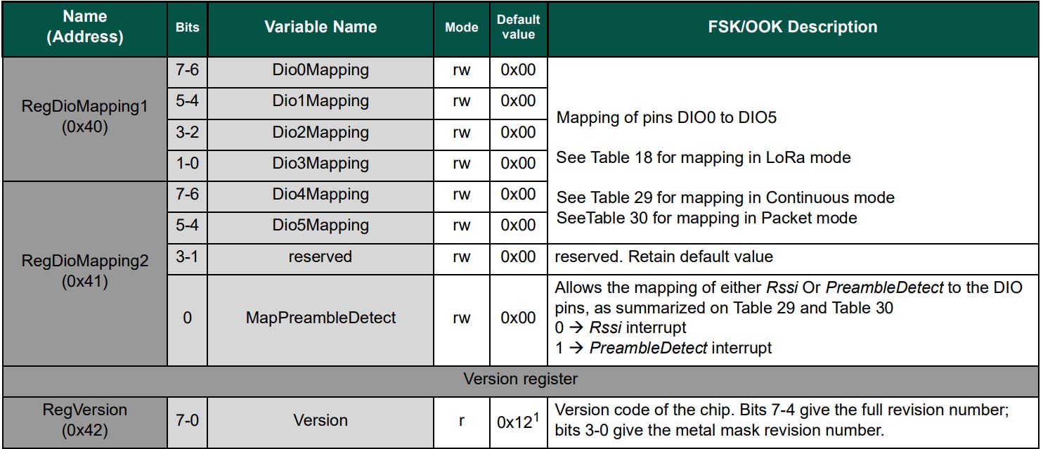
The Dio0 pin number is the only required pin number parameter, the resetPin, and Dio1 thru Dio5 pin numbers are optional. All the RegDioMapping1 and RegDioMapping2 mappings are disabled on intialisation so there should be no events while the SX127X is being configured.
public SX127XDevice(SpiDevice spiDevice, GpioController gpioController,
int dio0Pin,
int resetPin = 0, // Odd order so as not to break exisiting code
int dio1Pin = 0,
int dio2Pin = 0,
int dio3Pin = 0,
int dio4Pin = 0,
int dio5Pin = 0
)
{
_gpioController = gpioController;
// Factory reset pin configuration
if (resetPin != 0)
{
_resetPin = resetPin;
_gpioController.OpenPin(resetPin, PinMode.Output);
_gpioController.Write(resetPin, PinValue.Low);
Thread.Sleep(20);
_gpioController.Write(resetPin, PinValue.High);
Thread.Sleep(50);
}
_registerManager = new RegisterManager(spiDevice, RegisterAddressReadMask, RegisterAddressWriteMask);
// Once the pins setup check that SX127X chip is present
Byte regVersionValue = _registerManager.ReadByte((byte)Configuration.Registers.RegVersion);
if (regVersionValue != Configuration.RegVersionValueExpected)
{
throw new ApplicationException("Semtech SX127X not found");
}
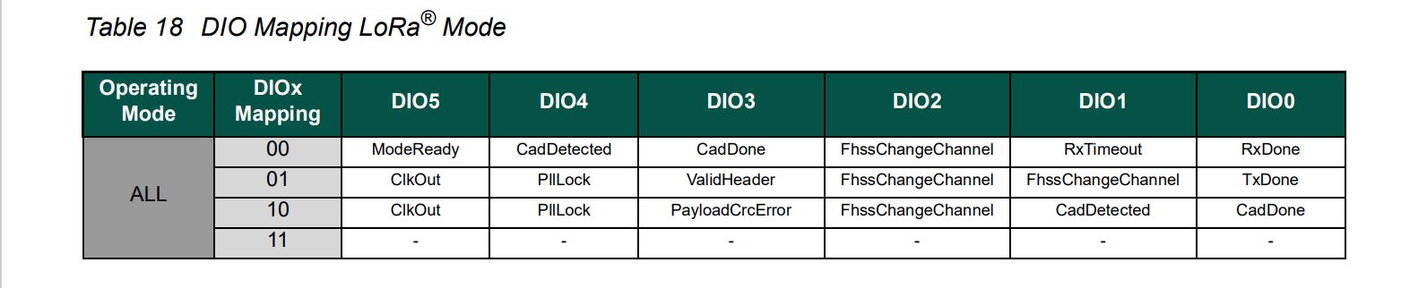
// See Table 18 DIO Mapping LoRa® Mode
Configuration.RegDioMapping1 regDioMapping1Value = Configuration.RegDioMapping1.Dio0None;
regDioMapping1Value |= Configuration.RegDioMapping1.Dio1None;
regDioMapping1Value |= Configuration.RegDioMapping1.Dio2None;
regDioMapping1Value |= Configuration.RegDioMapping1.Dio3None;
_registerManager.WriteByte((byte)Configuration.Registers.RegDioMapping1, (byte)regDioMapping1Value);
// Currently no easy way to test this with available hardware
//Configuration.RegDioMapping2 regDioMapping2Value = Configuration.RegDioMapping2.Dio4None;
//regDioMapping2Value = Configuration.RegDioMapping2.Dio5None;
//_registerManager.WriteByte((byte)Configuration.Registers.RegDioMapping2, (byte)regDioMapping2Value);
// Interrupt pin for RXDone, TXDone, and CadDone notification
_gpioController.OpenPin(dio0Pin, PinMode.InputPullDown);
_gpioController.RegisterCallbackForPinValueChangedEvent(dio0Pin, PinEventTypes.Rising, InterruptGpioPin_ValueChanged);
// RxTimeout, FhssChangeChannel, and CadDetected
if (dio1Pin != 0)
{
_gpioController.OpenPin(dio1Pin, PinMode.InputPullDown);
_gpioController.RegisterCallbackForPinValueChangedEvent(dio1Pin, PinEventTypes.Rising, InterruptGpioPin_ValueChanged);
}
// FhssChangeChannel, FhssChangeChannel, and FhssChangeChannel
if (dio2Pin != 0)
{
_gpioController.OpenPin(dio2Pin, PinMode.InputPullDown);
_gpioController.RegisterCallbackForPinValueChangedEvent(dio2Pin, PinEventTypes.Rising, InterruptGpioPin_ValueChanged);
}
// CadDone, ValidHeader, and PayloadCrcError
if (dio3Pin != 0)
{
_gpioController.OpenPin(dio3Pin, PinMode.InputPullDown);
_gpioController.RegisterCallbackForPinValueChangedEvent(dio3Pin, PinEventTypes.Rising, InterruptGpioPin_ValueChanged);
}
// CadDetected, PllLock and PllLock
if (dio4Pin != 0)
{
_gpioController.OpenPin(dio4Pin, PinMode.InputPullDown);
_gpioController.RegisterCallbackForPinValueChangedEvent(dio4Pin, PinEventTypes.Rising, InterruptGpioPin_ValueChanged);
}
// ModeReady, ClkOut and ClkOut
if (dio5Pin != 0)
{
_gpioController.OpenPin(dio5Pin, PinMode.InputPullDown);
_gpioController.RegisterCallbackForPinValueChangedEvent(dio5Pin, PinEventTypes.Rising, InterruptGpioPin_ValueChanged);
}
}
The same event handler (InterruptGpioPin_ValueChanged) is used for Dio0 thru Dio5. Each event has a “process” method and the RegIrqFlags register controls which one(s) are called.
private void InterruptGpioPin_ValueChanged(object sender, PinValueChangedEventArgs pinValueChangedEventArgs)
{
	Byte regIrqFlagsToClear = (byte)Configuration.RegIrqFlags.ClearNone;

	// Read RegIrqFlags to see what caused the interrupt
	Byte irqFlags = _registerManager.ReadByte((byte)Configuration.Registers.RegIrqFlags);

	//Console.WriteLine($"IrqFlags 0x{irqFlags:x} Pin:{pinValueChangedEventArgs.PinNumber}");

	// Check RxTimeout for inbound message
	if ((irqFlags & (byte)Configuration.RegIrqFlagsMask.RxTimeoutMask) == (byte)Configuration.RegIrqFlags.RxTimeout)
	{
		regIrqFlagsToClear |= (byte)Configuration.RegIrqFlags.RxTimeout;

		ProcessRxTimeout(irqFlags);
	}

	// Check RxDone for inbound message
	if ((irqFlags & (byte)Configuration.RegIrqFlagsMask.RxDoneMask) == (byte)Configuration.RegIrqFlags.RxDone)
	{
		regIrqFlagsToClear |= (byte)Configuration.RegIrqFlags.RxDone;

		ProcessRxDone(irqFlags);
	}

	// Check PayLoadCrcError for inbound message
	if ((irqFlags & (byte)Configuration.RegIrqFlagsMask.PayLoadCrcErrorMask) == (byte)Configuration.RegIrqFlags.PayLoadCrcError)
	{
		regIrqFlagsToClear |= (byte)Configuration.RegIrqFlags.PayLoadCrcError;

		ProcessPayloadCrcError(irqFlags);
	}

	// Check ValidHeader for inbound message
	if ((irqFlags & (byte)Configuration.RegIrqFlagsMask.ValidHeaderMask) == (byte)Configuration.RegIrqFlags.ValidHeader)
	{
		regIrqFlagsToClear |= (byte)Configuration.RegIrqFlags.ValidHeader;

		ProcessValidHeader(irqFlags);
	}

	// Check TxDone for outbound message
	if ((irqFlags & (byte)Configuration.RegIrqFlagsMask.TxDoneMask) == (byte)Configuration.RegIrqFlags.TxDone)
	{
		regIrqFlagsToClear |= (byte)Configuration.RegIrqFlags.TxDone;

		ProcessTxDone(irqFlags);
	}

	// Check Channel Activity Detection done
	if (((irqFlags & (byte)Configuration.RegIrqFlagsMask.CadDoneMask) == (byte)Configuration.RegIrqFlags.CadDone))
	{
		regIrqFlagsToClear |= (byte)Configuration.RegIrqFlags.CadDone;

		ProcessChannelActivityDetectionDone(irqFlags);
	}

	// Check FhssChangeChannel for inbound message
	if ((irqFlags & (byte)Configuration.RegIrqFlagsMask.FhssChangeChannelMask) == (byte)Configuration.RegIrqFlags.FhssChangeChannel)
	{
		regIrqFlagsToClear |= (byte)Configuration.RegIrqFlags.FhssChangeChannel;

		ProcessFhssChangeChannel(irqFlags);
	}

	// Check Channel Activity Detected
	if (((irqFlags & (byte)Configuration.RegIrqFlagsMask.CadDetectedMask) == (byte)Configuration.RegIrqFlags.CadDetected))
	{
		regIrqFlagsToClear |= (byte)Configuration.RegIrqFlags.CadDetected;

		ProcessChannelActivityDetected(irqFlags);
	}

	_registerManager.WriteByte((byte)Configuration.Registers.RegIrqFlags, regIrqFlagsToClear);
}

private void ProcessRxTimeout(byte irqFlags)
{
	OnRxTimeoutEventArgs onRxTimeoutArgs = new OnRxTimeoutEventArgs();

	OnRxTimeout?.Invoke(this, onRxTimeoutArgs);
}

private void ProcessRxDone(byte irqFlags)
{
	byte[] payloadBytes;
...
}
The RegIrqFlags bits are cleared individually (with regIrqFlagsToClear) at the end of the event handler. Initially I cleared all the flags by writing 0xFF to RegIrqFlags but this caused issues when there were multiple bits set e.g. CadDone along with CadDetected.
devMobile.IoT.SX127xLoRaDevice Client starting
Register dump
Register 0x01 - Value 0X80
...
Register 0x4d - Value 0X84

00:00:09-CAD Detection Done
00:00:09-CAD Detected
00:00:09-RX PacketSnr 0.0 Packet RSSI -100dBm RSSI -96dBm = 9 byte message hello 41
00:00:09-RX PacketSnr 0.0 Packet RSSI -100dBm RSSI -96dBm = 9 byte message hello 42
00:00:09-RX PacketSnr 0.0 Packet RSSI -100dBm RSSI -96dBm = 9 byte message hello 43
00:00:09-RX PacketSnr 0.0 Packet RSSI -100dBm RSSI -96dBm = 9 byte message hello 44
00:00:09-RX PacketSnr 0.0 Packet RSSI -100dBm RSSI -96dBm = 9 byte message hello 45
00:00:09-RX PacketSnr 0.0 Packet RSSI -100dBm RSSI -94dBm = 9 byte message hello 46
00:00:09-RX PacketSnr 0.0 Packet RSSI -99dBm RSSI -94dBm = 9 byte message hello 47
00:00:19-RX PacketSnr 0.0 Packet RSSI -100dBm RSSI -96dBm = 9 byte message hello 48
It took some experimentation with the SX127xLoRaDeviceClient application to “reliably” trigger events for testing. To generate CAD Detected event, I had to modify one of the Arduino-LoRa sample applications to send messages without a delay, then have it running as the SX127xLoRaDeviceClient application was starting.
