Random wanderings through Microsoft Azure esp. PaaS plumbing, the IoT bits, AI on Micro controllers, AI on Edge Devices, .NET nanoFramework, .NET Core on *nix and ML.NET+ONNX
This proof of concept (PoC) was to confirm I could configure the Semtech 127X then handle the received messages using a Meadow event handler. The event handler code is based on the implementation in my Windows IoT 10 Core library.
I had added a few Console.WriteLine statements (Debug.Print currently doesn’t work Dec 2019) so I could see what was going on. But, using Console.WriteLine in the event handler caused me some problems which I had to debug. The irqFlags bit mask indicated there was a message in the FIFO but it wasn’t displayed and the interrupt mask wasn’t getting reset. As a temporary fix I refactored the code so the Console.WriteLine was the last statement in the EventHandler(which may cause other issues).
public class MeadowApp : App<F7Micro, MeadowApp>
{
	private Rfm9XDevice rfm9XDevice;

	public MeadowApp()
	{
		ISpiBus spiBus = Device.CreateSpiBus(500);
		if (spiBus == null)
		{
			Console.WriteLine("spiBus == null");
		}

		rfm9XDevice = new Rfm9XDevice(Device, spiBus, Device.Pins.D09, Device.Pins.D11);

		// Put device into LoRa + Sleep mode
		rfm9XDevice.RegisterWriteByte(0x01, 0b10000000); // RegOpMode

		// Set the frequency to 915MHz
		byte[] frequencyWriteBytes = { 0xE4, 0xC0, 0x00 }; // RegFrMsb, RegFrMid, RegFrLsb
		rfm9XDevice.RegisterWrite(0x06, frequencyWriteBytes);

		rfm9XDevice.RegisterWriteByte(0x0F, 0x0); // RegFifoRxBaseAddress

		rfm9XDevice.RegisterWriteByte(0x01, 0b10000101); // RegOpMode set LoRa & RxContinuous

		while (true)
		{
			// Wait until a packet is received, no timeouts in PoC
			Console.WriteLine("Receive-Wait");
			byte IrqFlags = rfm9XDevice.RegisterReadByte(0x12); // RegIrqFlags
			while ((IrqFlags & 0b01000000) == 0)  // wait until RxDone cleared
			{
				Task.Delay(100).Wait();
				IrqFlags = rfm9XDevice.RegisterReadByte(0x12); // RegIrqFlags
				Console.Write(".");
			}
			Console.WriteLine("");
			Console.WriteLine(string.Format("RegIrqFlags {0}", Convert.ToString((byte)IrqFlags, 2).PadLeft(8, '0')));
			Console.WriteLine("Receive-Message");
			byte currentFifoAddress = rfm9XDevice.RegisterReadByte(0x10); // RegFifiRxCurrent
			rfm9XDevice.RegisterWriteByte(0x0d, currentFifoAddress); // RegFifoAddrPtr

			byte numberOfBytes = rfm9XDevice.RegisterReadByte(0x13); // RegRxNbBytes

			byte[] messageBytes = rfm9XDevice.RegisterRead(0x00, numberOfBytes); // RegFifo

			rfm9XDevice.RegisterWriteByte(0x0d, 0);
			rfm9XDevice.RegisterWriteByte(0x12, 0b11111111); // RegIrqFlags clear all the bits

			string messageText = UTF8Encoding.UTF8.GetString(messageBytes);
			Console.WriteLine("Received {0} byte message {1}", messageBytes.Length, messageText);

			Console.WriteLine("Receive-Done");
		}
	}
}
The receive code works reliably but has no error detection or correction capability, so every so often a message gets corrupted. Which is can be seen in the Debug output below.
'App.exe' (CLR v4.0.30319: DefaultDomain): Loaded 'C:\WINDOWS\Microsoft.Net\assembly\GAC_64\mscorlib\v4.0_4.0.0.0__b77a5c561934e089\mscorlib.dll'.
'App.exe' (CLR v4.0.30319: DefaultDomain): Loaded 'C:\Users\BrynLewis\source\repos\RFM9X.Meadow\ReceiveBasic\bin\Debug\net472\App.exe'. Symbols loaded.
'App.exe' (CLR v4.0.30319: App.exe): Loaded 'C:\Users\BrynLewis\source\repos\RFM9X.Meadow\ReceiveBasic\bin\Debug\net472\Meadow.dll'.
The program '[18208] App.exe: Program Trace' has exited with code 0 (0x0).
The program '[18208] App.exe' has exited with code 0 (0x0).
.
.
DirectRegisterAccess = True
.
.
Receive-Wait
RegIrqFlags 01010000
Receive-Message
Received 61 byte message ???LoRaIoT1Maduino2at 57.7,ah 64,wsa 2,wsg 4,wd 254.25,r 0.00,
Receive-Done
Receive-Wait
RegIrqFlags 01110000
Receive-Message
Received 60 byte message ???LoReE??????!???ngvyno2at,57/7-ah 6???,w???a 2,w?????????6,7$.13,r 0.00-
Receive-Done
Receive-Wait
RegIrqFlags 01010000
Receive-Message
Received 16 byte message HeLoRa World! 0
Receive-Done
Receive-Wait
RegIrqFlags 01000000
Receive-Message
Received 60 byte message ???LoRaIoT1Maduino2at 57.7,ah 64,wsa 1,wsg 2,wd 88.13,r 0.00,
Receive-Done
Receive-Wait
RegIrqFlags 01010000
Receive-Message
Received 16 byte message HeLoRa World! 2
Receive-Done
Receive-Wait
/*
  LoRa Duplex communication with Sync Word

  Sends a message every half second, and polls continually
  for new incoming messages. Sets the LoRa radio's Sync Word.

  Spreading factor is basically the radio's network ID. Radios with different
  Sync Words will not receive each other's transmissions. This is one way you
  can filter out radios you want to ignore, without making an addressing scheme.

  See the Semtech datasheet, http://www.semtech.com/images/datasheet/sx1276.pdf
  for more on Sync Word.

  created 28 April 2017
  by Tom Igoe
*/
#include <stdlib.h>
#include <LoRa.h>
const int csPin = PA4;          // LoRa radio chip select
const int resetPin = PC13;       // LoRa radio reset
const int irqPin = PA11;         // change for your board; must be a hardware interrupt pin

byte msgCount = 0;            // count of outgoing messages
int interval = 2000;          // interval between sends
long lastSendTime = 0;        // time of last packet send

void setup() {
  Serial.begin(9600);                   // initialize serial
  while (!Serial);

  Serial.println("LoRa Duplex - Set sync word");

  // override the default CS, reset, and IRQ pins (optional)
  LoRa.setPins(csPin, resetPin, irqPin);// set CS, reset, IRQ pin

  if (!LoRa.begin(915E6)) {             // initialize ratio at 915 MHz
    Serial.println("LoRa init failed. Check your connections.");
    while (true);                       // if failed, do nothing
  }

  LoRa.setSyncWord(0x12);           // ranges from 0-0xFF, default 0x34, see API docs

  LoRa.dumpRegisters(Serial);
  Serial.println("LoRa init succeeded.");
}

void loop() {
  if (millis() - lastSendTime > interval) {
    String message = "HeLoRa World! ";   // send a message
    message += msgCount;
    sendMessage(message);
    Serial.println("Sending " + message);
    lastSendTime = millis();            // timestamp the message
    interval = random(1000) + 10000;    // 10-11 seconds
    msgCount++;
  }

  // parse for a packet, and call onReceive with the result:
  onReceive(LoRa.parsePacket());
}

void sendMessage(String outgoing) {
  LoRa.beginPacket();                   // start packet
  LoRa.print(outgoing);                 // add payload
  LoRa.endPacket();                     // finish packet and send it
  msgCount++;                           // increment message ID
}

void onReceive(int packetSize) {
  if (packetSize == 0) return;          // if there's no packet, return

  // read packet header bytes:
  String incoming = "";

  while (LoRa.available()) {
    incoming += (char)LoRa.read();
  }

  Serial.println("Message: " + incoming);
  Serial.println("RSSI: " + String(LoRa.packetRssi()));
  Serial.println("Snr: " + String(LoRa.packetSnr()));
  Serial.println();
}
The Meadow application
	public class MeadowApp : App<F7Micro, MeadowApp>
	{
		private Rfm9XDevice rfm9XDevice;

		public MeadowApp()
		{
			ISpiBus spiBus = Device.CreateSpiBus(500);
			if (spiBus == null)
			{
				Console.WriteLine("spiBus == null");
			}

			rfm9XDevice = new Rfm9XDevice(Device, spiBus, Device.Pins.D09, Device.Pins.D11);

			// Put device into LoRa + Sleep mode
			rfm9XDevice.RegisterWriteByte(0x01, 0b10000000); // RegOpMode

			// Set the frequency to 915MHz
			byte[] frequencyWriteBytes = { 0xE4, 0xC0, 0x00 }; // RegFrMsb, RegFrMid, RegFrLsb
			rfm9XDevice.RegisterWrite(0x06, frequencyWriteBytes);

			// More power PA Boost
			rfm9XDevice.RegisterWriteByte(0x09, 0b10000000); // RegPaConfig

			while (true)
			{
				rfm9XDevice.RegisterWriteByte(0x0E, 0x0); // RegFifoTxBaseAddress

				// Set the Register Fifo address pointer
				rfm9XDevice.RegisterWriteByte(0x0D, 0x0); // RegFifoAddrPtr

				string messageText = "Hello LoRa!";

				// load the message into the fifo
				byte[] messageBytes = UTF8Encoding.UTF8.GetBytes(messageText);
				foreach (byte b in messageBytes)
				{
					rfm9XDevice.RegisterWriteByte(0x0, b); // RegFifo
				}

				// Set the length of the message in the fifo
				rfm9XDevice.RegisterWriteByte(0x22, (byte)messageBytes.Length); // RegPayloadLength

				Console.WriteLine("Sending {0} bytes message {1}", messageBytes.Length, messageText);
				/// Set the mode to LoRa + Transmit
				rfm9XDevice.RegisterWriteByte(0x01, 0b10000011); // RegOpMode

				// Wait until send done, no timeouts in PoC
				Console.WriteLine("Send-wait");
				byte IrqFlags = rfm9XDevice.RegisterReadByte(0x12); // RegIrqFlags
				while ((IrqFlags & 0b00001000) == 0)  // wait until TxDone cleared
				{
					Task.Delay(10).Wait();
					IrqFlags = rfm9XDevice.RegisterReadByte(0x12); // RegIrqFlags
					Console.Write(".");
				}
				Console.WriteLine("");
				rfm9XDevice.RegisterWriteByte(0x12, 0b00001000); // clear TxDone bit
				Console.WriteLine("Send-Done");

				Task.Delay(30000).Wait();
			}
		}
When I ran the meadow application after some messing around with the jumper wires.
'App.exe' (CLR v4.0.30319: DefaultDomain): Loaded 'C:\WINDOWS\Microsoft.Net\assembly\GAC_64\mscorlib\v4.0_4.0.0.0__b77a5c561934e089\mscorlib.dll'.
'App.exe' (CLR v4.0.30319: DefaultDomain): Loaded 'C:\Users\BrynLewis\source\repos\RFM9X.Meadow\TransmitBasic\bin\Debug\net472\App.exe'. Symbols loaded.
'App.exe' (CLR v4.0.30319: App.exe): Loaded 'C:\Users\BrynLewis\source\repos\RFM9X.Meadow\TransmitBasic\bin\Debug\net472\Meadow.dll'.
The program '[37572] App.exe: Program Trace' has exited with code 0 (0x0).
The program '[37572] App.exe' has exited with code 0 (0x0).
.
.
DirectRegisterAccess = True
.
.
Sending 11 bytes message Hello LoRa!
Send-wait
Send-Done
Sending 11 bytes message Hello LoRa!
Send-wait
.
Send-Done
I could the see the messages arriving at the Armtronix device in the Arduino monitor (the other messages in the monitor are my solar powered weather station and soil moisture monitoring node).
Now that I could reliably dump all the Arduino shield registers I wanted to be able to configure the Semtech 1276/7/8/9 device and reset it back to factory settings.
A factory reset is done by strobing the reset pin on the device. To support this my Rfm9XDevice class constructor gained an additional parameter, the reset GPIO pin.
Arduino shield connected to Meadow with jumper wires
To configure the RFM9X I wrote some wrapper functions for the MeadowSPIAPI to read/write byte values, word values and arrays of bytes. The Meadow APIs (Dec 2019) return an additional byte at the start of each reply (unlike the .NetMF and Windows 10 IoT Core APIs) which has to be removed.
Each method was tested by read/writing suitable register(s) in the device configuration (Needed to set it into LoRa mode first).
//---------------------------------------------------------------------------------
// Copyright (c) December 2019, devMobile Software
//
// Licensed under the Apache License, Version 2.0 (the "License");
// you may not use this file except in compliance with the License.
// You may obtain a copy of the License at
//
//     http://www.apache.org/licenses/LICENSE-2.0
//
// Unless required by applicable law or agreed to in writing, software
// distributed under the License is distributed on an "AS IS" BASIS,
// WITHOUT WARRANTIES OR CONDITIONS OF ANY KIND, either express or implied.
// See the License for the specific language governing permissions and
// limitations under the License.
//
//---------------------------------------------------------------------------------
namespace devMobile.IoT.Rfm9x.ReadAndWrite
{
   using System;
    using System.Diagnostics;
    using System.Runtime.InteropServices.WindowsRuntime;
    using System.Threading.Tasks;

   using Meadow;
   using Meadow.Devices;
   using Meadow.Hardware;

   public sealed class Rfm9XDevice
   {
      private SpiPeripheral Rfm9XLoraModem;
      private IDigitalOutputPort ChipSelectGpioPin;
		private const byte RegisterAddressReadMask = 0X7f;
		private const byte RegisterAddressWriteMask = 0x80;

		public Rfm9XDevice(IIODevice device, ISpiBus spiBus, IPin chipSelectPin, IPin resetPin)
      {
         // Chip select pin configuration
         ChipSelectGpioPin = device.CreateDigitalOutputPort(chipSelectPin, initialState: true);
         if (ChipSelectGpioPin == null)
         {
            Console.WriteLine("ChipSelectGpioPin == null");
         }

         // Factory reset pin configuration
         IDigitalOutputPort resetGpioPin = device.CreateDigitalOutputPort(resetPin);
         if (resetGpioPin == null)
         {
            Console.WriteLine("resetGpioPin == null");
         }
         resetGpioPin.State = false;
         Task.Delay(10);
         resetGpioPin.State = true;
         Task.Delay(10);

			Rfm9XLoraModem = new SpiPeripheral(spiBus, ChipSelectGpioPin);
         if (Rfm9XLoraModem == null)
         {
            Console.WriteLine("Rfm9XLoraModem == null");
         }
      }

      public Byte RegisterReadByte(byte address)
      {
         byte[] writeBuffer = new byte[] { address &= RegisterAddressReadMask };
			Debug.Assert(Rfm9XLoraModem != null);

			byte[] readBuffer = Rfm9XLoraModem.WriteRead(writeBuffer, 2);

         return readBuffer[1];
      }

		public ushort RegisterReadWord(byte address)
		{
			byte[] writeBuffer = new byte[] { address &= RegisterAddressReadMask };
			Debug.Assert(Rfm9XLoraModem != null);

			byte[] readBuffer = Rfm9XLoraModem.WriteRead(writeBuffer, 3);

			return (ushort)(readBuffer[2] + (readBuffer[1] << 8));
		}

		public byte[] RegisterRead(byte address, int length)
		{
			byte[] writeBuffer = new byte[] { address &= RegisterAddressReadMask };
			byte[] repyBuffer = new byte[length + 1];
			Debug.Assert(Rfm9XLoraModem != null);

			byte[] readBuffer = Rfm9XLoraModem.WriteRead(writeBuffer, (ushort)repyBuffer.Length);

			Array.Copy(readBuffer, 1, repyBuffer, 0, length);

			return repyBuffer;
		}

		public void RegisterWriteByte(byte address, byte value)
		{
			byte[] writeBuffer = new byte[] { address |= RegisterAddressWriteMask, value };
			Debug.Assert(Rfm9XLoraModem != null);

			Rfm9XLoraModem.WriteBytes(writeBuffer);
		}

		public void RegisterWriteWord(byte address, ushort value)
		{
			byte[] valueBytes = BitConverter.GetBytes(value);
			byte[] writeBuffer = new byte[] { address |= RegisterAddressWriteMask, valueBytes[0], valueBytes[1] };
			Debug.Assert(Rfm9XLoraModem != null);

			Rfm9XLoraModem.WriteBytes(writeBuffer);
		}
		public void RegisterWrite(byte address, [ReadOnlyArray()] byte[] bytes)
		{
			byte[] writeBuffer = new byte[1 + bytes.Length];
			Debug.Assert(Rfm9XLoraModem != null);

			Array.Copy(bytes, 0, writeBuffer, 1, bytes.Length);
			writeBuffer[0] = address |= RegisterAddressWriteMask;

			Rfm9XLoraModem.WriteBytes(writeBuffer);
		}

		public void RegisterDump()
		{
			Console.WriteLine("Register dump");
			for (byte registerIndex = 0; registerIndex <= 0x42; registerIndex++)
			{
				byte registerValue = this.RegisterReadByte(registerIndex);

				Console.WriteLine("Register 0x{0:x2} - Value 0X{1:x2} - Bits {2}", registerIndex, registerValue, Convert.ToString(registerValue, 2).PadLeft(8, '0'));
			}
		}
	}

	public class MeadowApp : App<F7Micro, MeadowApp>
   {
      private Rfm9XDevice rfm9XDevice;

      public MeadowApp()
      {
			ISpiBus spiBus = Device.CreateSpiBus(500);
         if (spiBus == null)
         {
            Console.WriteLine("spiBus == null");
         }

			rfm9XDevice = new Rfm9XDevice(Device, spiBus, Device.Pins.D09, Device.Pins.D11);

			while (true)
         {
				rfm9XDevice.RegisterDump();

				Byte regOpMode = rfm9XDevice.RegisterReadByte(0x1);

				Console.WriteLine("Set LoRa mode and sleep mode (write byte)");
				rfm9XDevice.RegisterWriteByte(0x01, 0b10000000); //

				Console.WriteLine("Read the preamble (read word)");
				ushort preamble = rfm9XDevice.RegisterReadWord(0x20);
				Console.WriteLine("Preamble 0x{0:x2} - Bits {1}", preamble, Convert.ToString(preamble, 2).PadLeft(16, '0'));

				Console.WriteLine("Set the preamble to 0x80 (write word)");
				rfm9XDevice.RegisterWriteWord(0x20, 0x80);

				Console.WriteLine("Read the centre frequency (read byte array)");
				byte[] frequencyReadBytes = rfm9XDevice.RegisterRead(0x06, 3);
				Console.WriteLine("Frequency Msb 0x{0:x2} Mid 0x{1:x2} Lsb 0x{2:x2}", frequencyReadBytes[0], frequencyReadBytes[1], frequencyReadBytes[2]);

				Console.WriteLine("Set the centre frequency to 916MHz ( write byte array)");
				byte[] frequencyWriteBytes = { 0xE4, 0xC0, 0x00 };
				rfm9XDevice.RegisterWrite(0x06, frequencyWriteBytes);

				rfm9XDevice.RegisterDump();

				Task.Delay(30000).Wait();
			}
		}
   }
}
The output of the application looked like this
'App.exe' (CLR v4.0.30319: DefaultDomain): Loaded 'C:\WINDOWS\Microsoft.Net\assembly\GAC_64\mscorlib\v4.0_4.0.0.0__b77a5c561934e089\mscorlib.dll'.
'App.exe' (CLR v4.0.30319: DefaultDomain): Loaded 'C:\Users\BrynLewis\source\repos\RFM9X.Meadow\RegisterReadAndWrite\bin\Debug\net472\App.exe'. Symbols loaded.
'App.exe' (CLR v4.0.30319: App.exe): Loaded 'C:\Users\BrynLewis\source\repos\RFM9X.Meadow\RegisterReadAndWrite\bin\Debug\net472\Meadow.dll'.
The program '[31296] App.exe: Program Trace' has exited with code 0 (0x0).
The program '[31296] App.exe' has exited with code 0 (0x0).
.
.
DirectRegisterAccess = True
==========================================================
Ignore the exceptions generated by the DateTime call here.
==========================================================
.
Register dump
.
Register 0x00 - Value 0X00 - Bits 00000000
Register 0x01 - Value 0X09 - Bits 00001001
Register 0x02 - Value 0X1a - Bits 00011010
Register 0x03 - Value 0X0b - Bits 00001011
Register 0x04 - Value 0X00 - Bits 00000000
Register 0x05 - Value 0X52 - Bits 01010010
Register 0x06 - Value 0X6c - Bits 01101100
Register 0x07 - Value 0X80 - Bits 10000000
Register 0x08 - Value 0X00 - Bits 00000000
Register 0x09 - Value 0X4f - Bits 01001111
Register 0x0a - Value 0X09 - Bits 00001001
Register 0x0b - Value 0X2b - Bits 00101011
Register 0x0c - Value 0X20 - Bits 00100000
Register 0x0d - Value 0X08 - Bits 00001000
Register 0x0e - Value 0X02 - Bits 00000010
Register 0x0f - Value 0X0a - Bits 00001010
Register 0x10 - Value 0Xff - Bits 11111111
Register 0x11 - Value 0X70 - Bits 01110000
Register 0x12 - Value 0X15 - Bits 00010101
Register 0x13 - Value 0X0b - Bits 00001011
Register 0x14 - Value 0X28 - Bits 00101000
Register 0x15 - Value 0X0c - Bits 00001100
Register 0x16 - Value 0X12 - Bits 00010010
Register 0x17 - Value 0X47 - Bits 01000111
Register 0x18 - Value 0X32 - Bits 00110010
Register 0x19 - Value 0X3e - Bits 00111110
Register 0x1a - Value 0X00 - Bits 00000000
Register 0x1b - Value 0X00 - Bits 00000000
Register 0x1c - Value 0X00 - Bits 00000000
Register 0x1d - Value 0X00 - Bits 00000000
Register 0x1e - Value 0X00 - Bits 00000000
Register 0x1f - Value 0X40 - Bits 01000000
Register 0x20 - Value 0X00 - Bits 00000000
Register 0x21 - Value 0X00 - Bits 00000000
Register 0x22 - Value 0X00 - Bits 00000000
Register 0x23 - Value 0X00 - Bits 00000000
Register 0x24 - Value 0X05 - Bits 00000101
Register 0x25 - Value 0X00 - Bits 00000000
Register 0x26 - Value 0X03 - Bits 00000011
Register 0x27 - Value 0X93 - Bits 10010011
Register 0x28 - Value 0X55 - Bits 01010101
Register 0x29 - Value 0X55 - Bits 01010101
Register 0x2a - Value 0X55 - Bits 01010101
Register 0x2b - Value 0X55 - Bits 01010101
Register 0x2c - Value 0X55 - Bits 01010101
Register 0x2d - Value 0X55 - Bits 01010101
Register 0x2e - Value 0X55 - Bits 01010101
Register 0x2f - Value 0X55 - Bits 01010101
Register 0x30 - Value 0X90 - Bits 10010000
Register 0x31 - Value 0X40 - Bits 01000000
Register 0x32 - Value 0X40 - Bits 01000000
Register 0x33 - Value 0X00 - Bits 00000000
Register 0x34 - Value 0X00 - Bits 00000000
Register 0x35 - Value 0X0f - Bits 00001111
Register 0x36 - Value 0X00 - Bits 00000000
Register 0x37 - Value 0X00 - Bits 00000000
Register 0x38 - Value 0X00 - Bits 00000000
Register 0x39 - Value 0Xf5 - Bits 11110101
Register 0x3a - Value 0X20 - Bits 00100000
Register 0x3b - Value 0X82 - Bits 10000010
Register 0x3c - Value 0X00 - Bits 00000000
Register 0x3d - Value 0X02 - Bits 00000010
Register 0x3e - Value 0X80 - Bits 10000000
Register 0x3f - Value 0X40 - Bits 01000000
Register 0x40 - Value 0X00 - Bits 00000000
Register 0x41 - Value 0X00 - Bits 00000000
Register 0x42 - Value 0X12 - Bits 00010010
Set LoRa mode and sleep mode (write byte)
Read the preamble (read word)
Preamble 0x08 - Bits 0000000000001000
Set the preamble to 0x80 (write word)
Read the centre frequency (read byte array)
Frequency Msb 0x6c Mid 0x80 Lsb 0x00
Set the centre frequency to 916MHz ( write byte array)
Register dump
Register 0x00 - Value 0Xf4 - Bits 11110100
Register 0x01 - Value 0X80 - Bits 10000000
Register 0x02 - Value 0X1a - Bits 00011010
Register 0x03 - Value 0X0b - Bits 00001011
Register 0x04 - Value 0X00 - Bits 00000000
Register 0x05 - Value 0X52 - Bits 01010010
Register 0x06 - Value 0Xe4 - Bits 11100100
Register 0x07 - Value 0Xc0 - Bits 11000000
Register 0x08 - Value 0X00 - Bits 00000000
Register 0x09 - Value 0X4f - Bits 01001111
Register 0x0a - Value 0X09 - Bits 00001001
Register 0x0b - Value 0X2b - Bits 00101011
Register 0x0c - Value 0X20 - Bits 00100000
Register 0x0d - Value 0X02 - Bits 00000010
Register 0x0e - Value 0X80 - Bits 10000000
Register 0x0f - Value 0X00 - Bits 00000000
Register 0x10 - Value 0X00 - Bits 00000000
Register 0x11 - Value 0X00 - Bits 00000000
Register 0x12 - Value 0X00 - Bits 00000000
Register 0x13 - Value 0X00 - Bits 00000000
Register 0x14 - Value 0X00 - Bits 00000000
Register 0x15 - Value 0X00 - Bits 00000000
Register 0x16 - Value 0X00 - Bits 00000000
Register 0x17 - Value 0X00 - Bits 00000000
Register 0x18 - Value 0X10 - Bits 00010000
Register 0x19 - Value 0X00 - Bits 00000000
Register 0x1a - Value 0X00 - Bits 00000000
Register 0x1b - Value 0X00 - Bits 00000000
Register 0x1c - Value 0X00 - Bits 00000000
Register 0x1d - Value 0X72 - Bits 01110010
Register 0x1e - Value 0X70 - Bits 01110000
Register 0x1f - Value 0X64 - Bits 01100100
Register 0x20 - Value 0X80 - Bits 10000000
Register 0x21 - Value 0X00 - Bits 00000000
Register 0x22 - Value 0X01 - Bits 00000001
Register 0x23 - Value 0Xff - Bits 11111111
Register 0x24 - Value 0X00 - Bits 00000000
Register 0x25 - Value 0X00 - Bits 00000000
Register 0x26 - Value 0X04 - Bits 00000100
Register 0x27 - Value 0X00 - Bits 00000000
Register 0x28 - Value 0X00 - Bits 00000000
Register 0x29 - Value 0X00 - Bits 00000000
Register 0x2a - Value 0X00 - Bits 00000000
Register 0x2b - Value 0X00 - Bits 00000000
Register 0x2c - Value 0X00 - Bits 00000000
Register 0x2d - Value 0X50 - Bits 01010000
Register 0x2e - Value 0X14 - Bits 00010100
Register 0x2f - Value 0X45 - Bits 01000101
Register 0x30 - Value 0X55 - Bits 01010101
Register 0x31 - Value 0Xc3 - Bits 11000011
Register 0x32 - Value 0X05 - Bits 00000101
Register 0x33 - Value 0X27 - Bits 00100111
Register 0x34 - Value 0X1c - Bits 00011100
Register 0x35 - Value 0X0a - Bits 00001010
Register 0x36 - Value 0X03 - Bits 00000011
Register 0x37 - Value 0X0a - Bits 00001010
Register 0x38 - Value 0X42 - Bits 01000010
Register 0x39 - Value 0X12 - Bits 00010010
Register 0x3a - Value 0X49 - Bits 01001001
Register 0x3b - Value 0X1d - Bits 00011101
Register 0x3c - Value 0X00 - Bits 00000000
Register 0x3d - Value 0Xaf - Bits 10101111
Register 0x3e - Value 0X00 - Bits 00000000
Register 0x3f - Value 0X00 - Bits 00000000
Register 0x40 - Value 0X00 - Bits 00000000
Register 0x41 - Value 0X00 - Bits 00000000
Register 0x42 - Value 0X12 - Bits 00010010
The next step is to extract the SPI register access functionality into a module and configure the bare minimum of settings required to get the RFM9X to transmit.
Next step was to dump all registers (0x00 thru 0x42) of the SX1276/7/8/9 device
//---------------------------------------------------------------------------------
// Copyright (c) December 2019, devMobile Software
//
// Licensed under the Apache License, Version 2.0 (the "License");
// you may not use this file except in compliance with the License.
// You may obtain a copy of the License at
//
//     http://www.apache.org/licenses/LICENSE-2.0
//
// Unless required by applicable law or agreed to in writing, software
// distributed under the License is distributed on an "AS IS" BASIS,
// WITHOUT WARRANTIES OR CONDITIONS OF ANY KIND, either express or implied.
// See the License for the specific language governing permissions and
// limitations under the License.
//
//---------------------------------------------------------------------------------
namespace devMobile.IoT.Rfm9x.RegisterScan
{
   using System;
   using System.Threading.Tasks;

   using Meadow;
   using Meadow.Devices;
   using Meadow.Hardware;

   public sealed class Rfm9XDevice
   {
      private SpiPeripheral sx127xDevice;
      private IDigitalOutputPort spiPeriphChipSelect;

      public Rfm9XDevice(IIODevice device, ISpiBus spiBus, IPin chipSelectPin)
      {
         spiPeriphChipSelect = device.CreateDigitalOutputPort(chipSelectPin, initialState: true);
         if (spiPeriphChipSelect == null)
         {
            Console.WriteLine("spiPeriphChipSelect == null");
         }

         sx127xDevice = new SpiPeripheral(spiBus, spiPeriphChipSelect);
         if (sx127xDevice == null)
         {
            Console.WriteLine("sx127xDevice == null");
         }
      }

      public Byte RegisterReadByte(byte registerAddress)
      {
         byte[] txBuffer = new byte[] { registerAddress };

         byte[] rxBuffer = sx127xDevice.WriteRead(txBuffer, 2);

         return rxBuffer[1];
      }
   }

   public class MeadowApp : App<F7Micro, MeadowApp>
   {
      private Rfm9XDevice rfm9XDevice;

      public MeadowApp()
      {
         ISpiBus spiBus = Device.CreateSpiBus(500);
         if (spiBus == null)
         {
            Console.WriteLine("spiBus == null");
         }

         rfm9XDevice = new Rfm9XDevice(Device, spiBus, Device.Pins.D09);

         while (true)
         {
            for (byte registerIndex = 0; registerIndex <= 0x42; registerIndex++)
            {
               byte registerValue = rfm9XDevice.RegisterReadByte(registerIndex);

               Console.WriteLine("Register 0x{0:x2} - Value 0X{1:x2} - Bits {2}", registerIndex, registerValue, Convert.ToString(registerValue, 2).PadLeft(8, '0'));
            }

            Task.Delay(10000).Wait();
         }
      }
   }
}
The output of the application looked like this
'App.exe' (CLR v4.0.30319: DefaultDomain): Loaded 'C:\WINDOWS\Microsoft.Net\assembly\GAC_64\mscorlib\v4.0_4.0.0.0__b77a5c561934e089\mscorlib.dll'.
'App.exe' (CLR v4.0.30319: DefaultDomain): Loaded 'C:\Users\BrynLewis\source\repos\RFM9X.Meadow\RegisterScan\bin\Debug\net472\App.exe'. Symbols loaded.
'App.exe' (CLR v4.0.30319: App.exe): Loaded 'C:\Users\BrynLewis\source\repos\RFM9X.Meadow\RegisterScan\bin\Debug\net472\Meadow.dll'.
The program '[3148] App.exe: Program Trace' has exited with code 0 (0x0).
The program '[3148] App.exe' has exited with code 0 (0x0).
.
.
DirectRegisterAccess = True
==========================================================
Ignore the exceptions generated by the DateTime call here.
==========================================================
.
Register 0x00 - Value 0X00 - Bits 00000000
Register 0x01 - Value 0X09 - Bits 00001001
Register 0x02 - Value 0X1a - Bits 00011010
Register 0x03 - Value 0X0b - Bits 00001011
Register 0x04 - Value 0X00 - Bits 00000000
Register 0x05 - Value 0X52 - Bits 01010010
Register 0x06 - Value 0X6c - Bits 01101100
Register 0x07 - Value 0X80 - Bits 10000000
Register 0x08 - Value 0X00 - Bits 00000000
Register 0x09 - Value 0X4f - Bits 01001111
Register 0x0a - Value 0X09 - Bits 00001001
Register 0x0b - Value 0X2b - Bits 00101011
Register 0x0c - Value 0X20 - Bits 00100000
Register 0x0d - Value 0X08 - Bits 00001000
Register 0x0e - Value 0X02 - Bits 00000010
Register 0x0f - Value 0X0a - Bits 00001010
Register 0x10 - Value 0Xff - Bits 11111111
Register 0x11 - Value 0X71 - Bits 01110001
Register 0x12 - Value 0X15 - Bits 00010101
Register 0x13 - Value 0X0b - Bits 00001011
Register 0x14 - Value 0X28 - Bits 00101000
Register 0x15 - Value 0X0c - Bits 00001100
Register 0x16 - Value 0X12 - Bits 00010010
Register 0x17 - Value 0X47 - Bits 01000111
Register 0x18 - Value 0X32 - Bits 00110010
Register 0x19 - Value 0X3e - Bits 00111110
Register 0x1a - Value 0X00 - Bits 00000000
Register 0x1b - Value 0X00 - Bits 00000000
Register 0x1c - Value 0X00 - Bits 00000000
Register 0x1d - Value 0X00 - Bits 00000000
Register 0x1e - Value 0X00 - Bits 00000000
Register 0x1f - Value 0X40 - Bits 01000000
Register 0x20 - Value 0X00 - Bits 00000000
Register 0x21 - Value 0X00 - Bits 00000000
Register 0x22 - Value 0X00 - Bits 00000000
Register 0x23 - Value 0X00 - Bits 00000000
Register 0x24 - Value 0X05 - Bits 00000101
Register 0x25 - Value 0X00 - Bits 00000000
Register 0x26 - Value 0X03 - Bits 00000011
Register 0x27 - Value 0X93 - Bits 10010011
Register 0x28 - Value 0X55 - Bits 01010101
Register 0x29 - Value 0X55 - Bits 01010101
Register 0x2a - Value 0X55 - Bits 01010101
Register 0x2b - Value 0X55 - Bits 01010101
Register 0x2c - Value 0X55 - Bits 01010101
Register 0x2d - Value 0X55 - Bits 01010101
Register 0x2e - Value 0X55 - Bits 01010101
Register 0x2f - Value 0X55 - Bits 01010101
Register 0x30 - Value 0X90 - Bits 10010000
Register 0x31 - Value 0X40 - Bits 01000000
Register 0x32 - Value 0X40 - Bits 01000000
Register 0x33 - Value 0X00 - Bits 00000000
Register 0x34 - Value 0X00 - Bits 00000000
Register 0x35 - Value 0X0f - Bits 00001111
Register 0x36 - Value 0X00 - Bits 00000000
Register 0x37 - Value 0X00 - Bits 00000000
Register 0x38 - Value 0X00 - Bits 00000000
Register 0x39 - Value 0Xf5 - Bits 11110101
Register 0x3a - Value 0X20 - Bits 00100000
Register 0x3b - Value 0X82 - Bits 10000010
Register 0x3c - Value 0Xfd - Bits 11111101
Register 0x3d - Value 0X02 - Bits 00000010
Register 0x3e - Value 0X80 - Bits 10000000
Register 0x3f - Value 0X40 - Bits 01000000
Register 0x40 - Value 0X00 - Bits 00000000
Register 0x41 - Value 0X00 - Bits 00000000
Register 0x42 - Value 0X12 - Bits 00010010
I also started to refactor the code, passing the Meadow IIODevice & ISpiBus into the constructor, and extracting the Read functionality.
The device was not in LoRa mode (Bit 7 of RegOpMode 0x01) so the next step was to read and write registers so I could change its configuration.
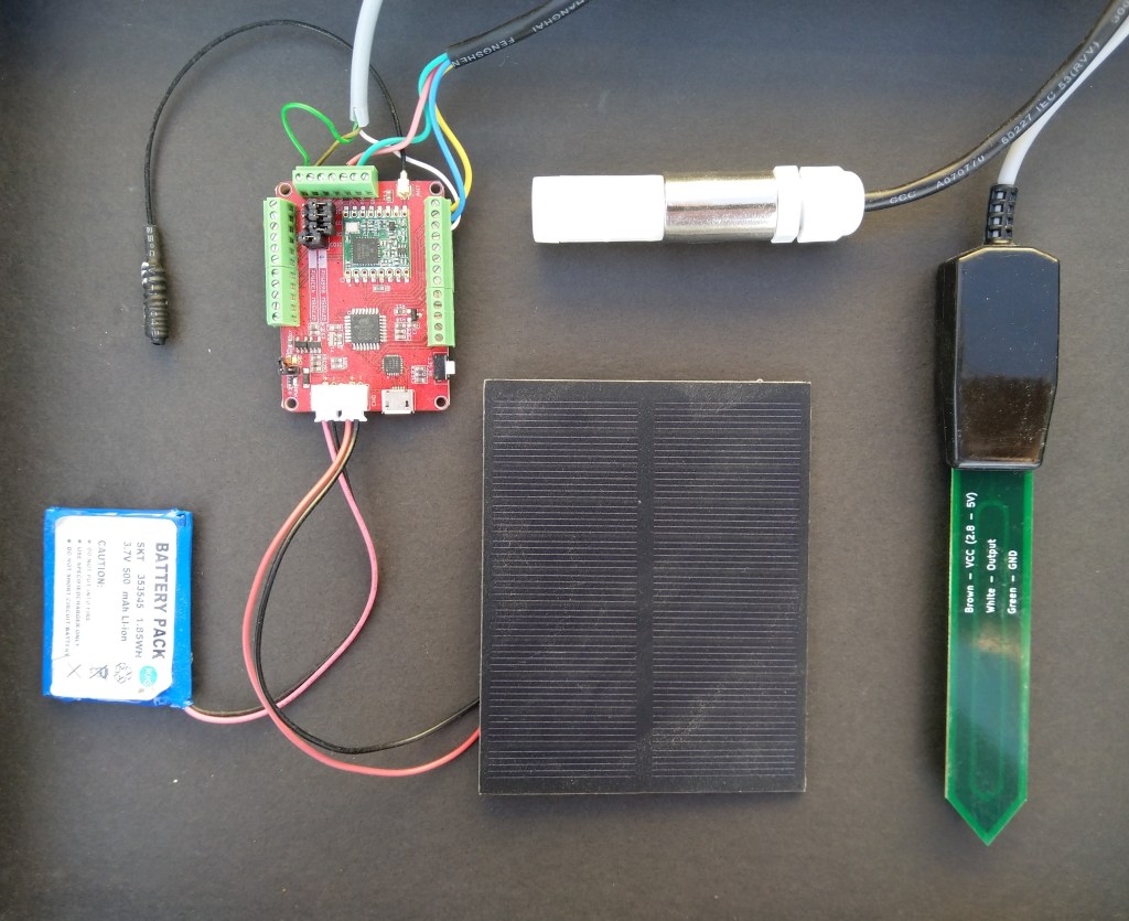
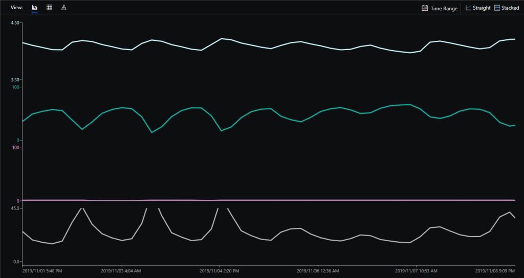
Sample hardwareAzure IoT Central data visualisation
The Maduino device in the picture is a custom version with an onboard Microchip ATSHA204 crypto and authentication chip (currently only use for the unique 72 bit serial number) and a voltage divider connected to the analog pin A6 to monitor the battery voltage.
There are compile time options ATSHA204 & BATTERY_VOLTAGE_MONITOR which can be used to selectively enable this functionality.
I use the Arduino lowpower library to aggressively sleep the device between measurements
// Adjust the delay so period is close to desired sec as possible, first do 8sec chunks.
  int delayCounter = SensorUploadDelay / 8 ;
  for( int i = 0 ; i < delayCounter ; i++ )
  {
     LowPower.powerDown(SLEEP_8S, ADC_OFF, BOD_OFF);
  }

  // Then to 4 sec chunk
  delayCounter =  ( SensorUploadDelay % 8 ) / 4;
  for( int i = 0 ; i < delayCounter ; i++ )
  {
     LowPower.powerDown(SLEEP_4S, ADC_OFF, BOD_OFF);
  }

  // Then to 2 sec chunk
  delayCounter =  ( SensorUploadDelay % 4 ) / 2 ;
  for( int i = 0 ; i < delayCounter ; i++ )
  {
     LowPower.powerDown(SLEEP_2S, ADC_OFF, BOD_OFF);
  }

  // Then to 1 sec chunk
  delayCounter =  ( SensorUploadDelay % 2 ) ;
  for( int i = 0 ; i < delayCounter ; i++ )
  {
     LowPower.powerDown(SLEEP_1S, ADC_OFF, BOD_OFF);
  }
}
I use a spare digital PIN for powering the soil moisture probe so it can be powered down when not in use. I have included a short delay after powering up the device to allow the reading to settle.
  // Turn on soil mosture sensor, take reading then turn off to save power
  digitalWrite(SoilMoistureSensorEnablePin, HIGH);
  delay(SoilMoistureSensorEnableDelay);
  int soilMoistureADCValue = analogRead(SoilMoistureSensorPin);
  digitalWrite(SoilMoistureSensorEnablePin, LOW);
  int soilMoisture = map(soilMoistureADCValue,SoilMoistureSensorMinimum,SoilMoistureSensorMaximum, SoilMoistureValueMinimum, SoilMoistureValueMaximum);
  PayloadAdd( "s", soilMoisture, false);
After problems with interleaved interrupt handling in my Windows 10 IoT Core client I figured the AutoMode used by the plainRFM69 library might be worth investigation. My first Arduino client was based on the plainRFM69 library but had Interoperability issues.
For this attempt I also started with the minimal sample and modified the code to send and receive text messages.
/*
    Copyright (c) 2014, Ivor Wanders, Bryn Lewis 2019
    MIT License, see the LICENSE.md file in the root folder.
*/

#include <SPI.h>
#include <plainRFM69.h>

// slave select pin.
#define SLAVE_SELECT_PIN 10

// connected to the reset pin of the RFM69.
#define RESET_PIN 9

// tie this pin down on the receiver.
#define SENDER_DETECT_PIN A0

const uint8_t tx_buffer[] = "ABCDEFGHIJKLMNOPQRSTURWXYZ1234567890";
//const uint8_t tx_buffer[] = "abcdefghijklmnopqrstuvwxyz1234567890";
uint8_t rx_buffer[sizeof(tx_buffer)] = "";

plainRFM69 rfm = plainRFM69(SLAVE_SELECT_PIN);


void sender() {

  uint32_t start_time = millis();

  uint32_t counter = 1; // the counter which we are going to send.

  while (true) {
    rfm.poll(); // run poll as often as possible.

    if (!rfm.canSend()) {
      continue; // sending is not possible, already sending.
    }

    if ((millis() - start_time) > 1000) { // every 500 ms.
      start_time = millis();

      // be a little bit verbose.
      Serial.print("Send:"); Serial.println(counter);

      // send the number of bytes equal to that set with setPacketLength.
      // read those bytes from memory where counter starts.
      rfm.sendVariable(tx_buffer, counter);

      counter++; // increase the counter.

      if ( counter > strlen(tx_buffer))
      {
        counter = 1;
      }
    }
  }
}

void receiver() {
  uint32_t counter = 0; // to count the messages.

  while (true) {

    rfm.poll(); // poll as often as possible.

    while (rfm.available())
    {
      uint8_t len = rfm.read(rx_buffer); // read the packet into the new_counter.

      // print verbose output.
      Serial.print("Packet Len:");
      Serial.print( len );
      Serial.print(" : ");
      Serial.println((char*)rx_buffer);
    }
  }
}

void setup() {
  Serial.begin(9600);
  SPI.begin();

  bareRFM69::reset(RESET_PIN); // sent the RFM69 a hard-reset.

  //rfm.setRecommended(); // set recommended paramters in RFM69.
  rfm.setPacketType(true, false); // set the used packet type.

  rfm.setBufferSize(2);   // set the internal buffer size.
  rfm.setPacketLength(sizeof(rx_buffer)); // set the packet length.

  rfm.setFrequency((uint32_t)909560000); // set the frequency.

  rfm.setLNA(RFM69_LNA_IMP_200OHM, RFM69_LNA_GAIN_AGC_LOOP);

  // p71, 3 preamble bytes.
  rfm.setPreambleSize(16);

  // p71, 4 bytes sync of 0x01, only start listening when sync is matched.
  //uint8_t syncthing[] = {0xaa, 0x2d, 0xd4};
  uint8_t syncthing[] = {0xd4, 0x2d, 0xaa};
  rfm.setSyncConfig(true, false, sizeof(syncthing), 0);
  rfm.setSyncValue(&syncthing, sizeof(syncthing));

  rfm.dumpRegisters(Serial);

  // baudrate is default, 4800 bps now.

  rfm.receive();
  // set it to receiving mode.

  pinMode(SENDER_DETECT_PIN, INPUT_PULLUP);
  delay(5);
}

void loop() {
  if (digitalRead(SENDER_DETECT_PIN) == LOW) {
    Serial.println("Going Receiver!");
    receiver();
    // this function never returns and contains an infinite loop.
  } else {
    Serial.println("Going sender!");
    sender();
    // idem.
  }
}
I took the list register values and loaded them into a Excel spreadsheet alongside the values from my Windows 10 IoT Core application
First thing I noticed was the order of the three sync byes (Registers 0x2F, 0x30, 0x31) was reversed. I then modified the run method in the Windows 10 code so the registers settings on both devices matched. (I removed the PlainRFM69 SetRecommended call so as many of the default options as possible were used).
I also found an error with the declaration of the RegPacketConfig1DcFree enumeration (Whitening = 0b0100000 vs. Whitening = 0b01000000) which wouldn’t have helped.
Register 0x4c - Value 0X00 - Bits 00000000
Register 0x4d - Value 0X00 - Bits 00000000
...
17:55:53.559 Received 1 byte message A CRC Ok True
.17:55:54.441 Received 2 byte message AB CRC Ok True
.17:55:55.444 Received 3 byte message ABC CRC Ok True
.17:55:56.447 Received 4 byte message ABCD CRC Ok True
.17:55:57.449 Received 5 byte message ABCDE CRC Ok True
.17:55:58.453 Received 6 byte message ABCDEF CRC Ok True
The thread 0x578 has exited with code 0 (0x0).
.17:55:59.622 Received 7 byte message ABCDEFG CRC Ok True
.17:56:00.457 Received 8 byte message ABCDEFGH CRC Ok True
.17:56:01.460 Received 9 byte message ABCDEFGHI CRC Ok True
.17:56:02.463 Received 10 byte message ABCDEFGHIJ CRC Ok True
..17:56:03.955 Received 11 byte message ABCDEFGHIJK CRC Ok True
17:56:04.583 Received 12 byte message ABCDEFGHIJKL CRC Ok True
I did some investigation into that the plainRMF69 code and found the ReadMultiple and WriteMuliple methods reverse the byte order
void bareRFM69::writeMultiple(uint8_t reg, void* data, uint8_t len){
    SPI.beginTransaction(SPISettings(10000000, MSBFIRST, SPI_MODE0));  // gain control of SPI bus
    this->chipSelect(true); // assert chip select
    SPI.transfer(RFM69_WRITE_REG_MASK | (reg & RFM69_READ_REG_MASK));
    uint8_t* r = reinterpret_cast<uint8_t*>(data);
    for (uint8_t i=0; i < len ; i++){
        SPI.transfer(r[len - i - 1]);
    }
    this->chipSelect(false);// deassert chip select
    SPI.endTransaction();    // release the SPI bus
}

void bareRFM69::readMultiple(uint8_t reg, void* data, uint8_t len){
    SPI.beginTransaction(SPISettings(10000000, MSBFIRST, SPI_MODE0));  // gain control of SPI bus
    this->chipSelect(true); // assert chip select

    SPI.transfer((reg % RFM69_READ_REG_MASK));
    uint8_t* r = reinterpret_cast<uint8_t*>(data);
    for (uint8_t i=0; i < len ; i++){
        r[len - i - 1] = SPI.transfer(0);
    }
    this->chipSelect(false);// deassert chip select
    SPI.endTransaction();    // release the SPI bus
}
I won’t be able to use interrupt AutoMode clients with the EasySensors shields as the DIO2 pin is not connected but on the AdaFruit RFM69HCW Radio Bonnet 433MHz or 915MHz it is connected to GPIO24.
In the Arduino code I found the order of initialisation was critical. Because of the way the Rasmatic library is written the call to vRF69SetAesKey has to be after the vInitialize.
The next step will be merging and refactoring the test harness to extract the code for accessing the RFM69 registers into a separate class, then defining enumerations and constants for all the RFM69 settings.
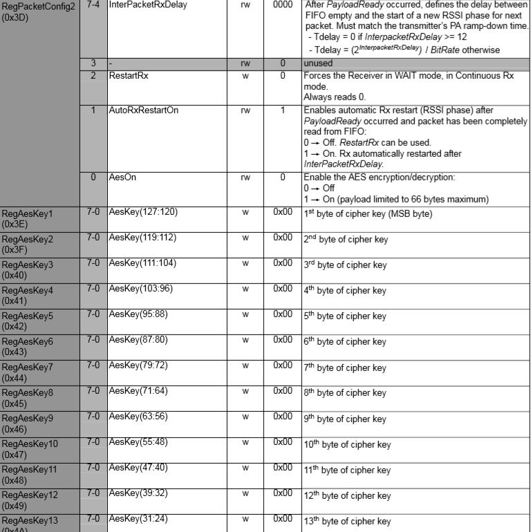
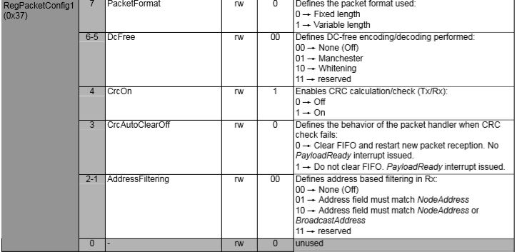
The RFM69CW/RFM69HCW modules (based on the Semtech SX1231/SX1231H) have built in support for addressing individual devices (register RegNodeAdrs 0x39) or broadcasting to groups of devices (register RegBroadcastAdrs 0x3A). In this test harness I’m exploring the RFM69 device support for these two different addressing modes which is configured in RegPacketConfig1 0x37.
RFM69 Address filtering options
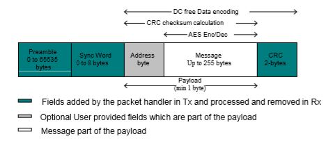
The fixed length packet format contains the following fields
Preamble (1010…)
Sync word (Network ID)
Optional Address byte (Node ID)
Message data
Optional 2-bytes CRC checksum
Fixed length packet format
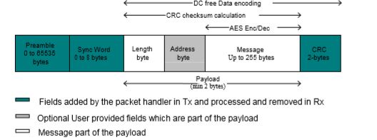
The variable length packet format contains the following fields
Preamble (1010…)
Sync word (Network ID)
Length byte
Optional Address byte (Node ID)
Message data
Optional 2-bytes CRC checksum
Variable length packet format
My first attempt at addressing was by modifying the payload (the extra space at the start of the payload was replaced by the target device address)
Initially it truncated messages because I neglected to include the byte with the length of the message in the length of the message. I also had to extend the timeout for sending a message a bit more than I expected for one extra byte.
bool RMRFM69::bSendMessage(byte address, byte msg[], byte length)
{
byte tmp;
 uint32_t overtime;
 word bittime;

 switch(COB)
	{
	case RFM65:									//only for Rx
	case RFM65C:
		return(false);
	case RFM69H:
	case RFM69HC:
 		vSpiWrite(((word)RegTestPa1<<8)+0x5D);		//for HighPower
	 	vSpiWrite(((word)RegTestPa2<<8)+0x7C);
		break;
	default:
	case RFM69:
	case RFM69C:
	 	vSpiWrite(((word)RegTestPa1<<8)+0x55);		//for NormalMode or RxMode
 		vSpiWrite(((word)RegTestPa2<<8)+0x70);
		break;
	}

 vSpiWrite(((word)RegDioMapping1<<8)+0x04);	//DIO0 PacketSend  / DIO1 FiflLevel / DIO2 Data /DIO3 FifoFull

 if(!FixedPktLength)
 	vSpiWrite(((word)RegFifo<<8)+length+1);
 vSpiWrite(((word)RegFifo<<8)+address);

 vSpiBurstWrite(RegFifo, msg, length);

 tmp = bSpiRead(RegOpMode);
 tmp&= MODE_MASK;
 tmp |= RADIO_TX;
 vSpiWrite(((word)RegOpMode<<8)+tmp);

 //�ȴ��������
 bittime  = SymbolTime/1000;		//unit: us
 overtime = SyncLength+PreambleLength+length+1;
 if(!FixedPktLength)				//SyncWord & PktLength & 2ByteCRC
    overtime += 1;
 if(!CrcDisable)
 	overtime += 2;
 overtime<<=3;					//8bit == 1byte
 overtime*= bittime;
 overtime/= 1000;				//unit: ms
 if(overtime==0)
 	overtime = 1;
 overtime += (overtime>>3);		//add 12.5% for ensure
 delay(overtime);			//
 for(tmp=0;tmp<1000;tmp++)		//about 50ms for overtime
 	{
 	if(digitalRead(_dio0Pin))
 		break;
 	delayMicroseconds(500);
 	}
 vGoStandby();
 if(tmp>=200)
 	return(false);
 else
 	return(true);
}
The Windows 10 IoT Core library interrupt handler needed some modification to display message only when the address matched and I also displayed the targeted address so I could check that device and broadcast addressing was working
/*
    Copyright ® 2019 July devMobile Software, All Rights Reserved

	 MIT License

	 Permission is hereby granted, free of charge, to any person obtaining a copy
	 of this software and associated documentation files (the "Software"), to deal
    in the Software without restriction, including without limitation the rights
	 to use, copy, modify, merge, publish, distribute, sublicense, and/or sell
	 copies of the Software, and to permit persons to whom the Software is
    furnished to do so, subject to the following conditions:

    The above copyright notice and this permission notice shall be included in all
	 copies or substantial portions of the Software.

    THE SOFTWARE IS PROVIDED "AS IS", WITHOUT WARRANTY OF ANY KIND, EXPRESS OR
	 IMPLIED, INCLUDING BUT NOT LIMITED TO THE WARRANTIES OF MERCHANTABILITY,
    FITNESS FOR A PARTICULAR PURPOSE AND NONINFRINGEMENT. IN NO EVENT SHALL THE
	 AUTHORS OR COPYRIGHT HOLDERS BE LIABLE FOR ANY CLAIM, DAMAGES OR OTHER
	 LIABILITY, WHETHER IN AN ACTION OF CONTRACT, TORT OR OTHERWISE, ARISING FROM,
    OUT OF OR IN CONNECTION WITH THE SOFTWARE OR THE USE OR OTHER DEALINGS IN THE
	 SOFTWARE

 */
namespace devMobile.IoT.Rfm69Hcw.Addressing
{
	using System;
	using System.Diagnostics;
	using System.Runtime.InteropServices.WindowsRuntime;
	using System.Text;
	using System.Threading.Tasks;
	using Windows.ApplicationModel.Background;
	using Windows.Devices.Gpio;
	using Windows.Devices.Spi;

	public sealed class Rfm69HcwDevice
	{
		private SpiDevice Rfm69Hcw;
		private GpioPin InterruptGpioPin = null;
		private const byte RegisterAddressReadMask = 0X7f;
		private const byte RegisterAddressWriteMask = 0x80;

		public Rfm69HcwDevice(int chipSelectPin, int resetPin, int interruptPin)
		{
			SpiController spiController = SpiController.GetDefaultAsync().AsTask().GetAwaiter().GetResult();
			var settings = new SpiConnectionSettings(chipSelectPin)
			{
				ClockFrequency = 500000,
				Mode = SpiMode.Mode0,
			};

			// Factory reset pin configuration
			GpioController gpioController = GpioController.GetDefault();
			GpioPin resetGpioPin = gpioController.OpenPin(resetPin);
			resetGpioPin.SetDriveMode(GpioPinDriveMode.Output);
			resetGpioPin.Write(GpioPinValue.High);
			Task.Delay(100);
			resetGpioPin.Write(GpioPinValue.Low);
			Task.Delay(10);

			// Interrupt pin for RX message & TX done notification
			InterruptGpioPin = gpioController.OpenPin(interruptPin);
			resetGpioPin.SetDriveMode(GpioPinDriveMode.Input);

			InterruptGpioPin.ValueChanged += InterruptGpioPin_ValueChanged;

			Rfm69Hcw = spiController.GetDevice(settings);
		}

		private void InterruptGpioPin_ValueChanged(GpioPin sender, GpioPinValueChangedEventArgs args)
		{
			if (args.Edge != GpioPinEdge.RisingEdge)
			{
				return;
			}

			byte irqFlags2 = this.RegisterReadByte(0x28); // RegIrqFlags2
			Debug.WriteLine("{0:HH:mm:ss.fff} RegIrqFlags2 {1}", DateTime.Now, Convert.ToString((byte)irqFlags2, 2).PadLeft(8, '0'));
			if ((irqFlags2 & 0b00000100) == 0b00000100)  // PayLoadReady set
			{
				byte irqFlags1 = this.RegisterReadByte(0x27); // RegIrqFlags1

				// Read the length of the buffer
				byte numberOfBytes = this.RegisterReadByte(0x0);

				Debug.WriteLine("{0:HH:mm:ss.fff} RegIrqFlags1 {1}", DateTime.Now, Convert.ToString((byte)irqFlags1, 2).PadLeft(8, '0'));
				if ((irqFlags1 & 0b00000001) == 0b00000001)  // SyncAddressMatch
				{
					byte address = this.RegisterReadByte(0x0);
					Debug.WriteLine("{0:HH:mm:ss.fff} Address 0X{1:X2} b{2}", DateTime.Now, address, Convert.ToString((byte)address, 2).PadLeft(8, '0'));
					numberOfBytes--;
				}

				// Allocate buffer for message
				byte[] messageBytes = new byte[numberOfBytes];

				for (int i = 0; i < numberOfBytes; i++)
				{
					messageBytes[i] = this.RegisterReadByte(0x00); // RegFifo
				}

				string messageText = UTF8Encoding.UTF8.GetString(messageBytes);
				Debug.WriteLine("{0:HH:mm:ss} Received:{1} byte message({2})", DateTime.Now, messageBytes.Length, messageText);
			}

			if ((irqFlags2 & 0b00001000) == 0b00001000)  // PacketSent set
			{
				this.RegisterWriteByte(0x01, 0b00010000); // RegOpMode set ReceiveMode
				Debug.WriteLine("{0:HH:mm:ss.fff} Transmit-Done", DateTime.Now);
			}
		}

		public Byte RegisterReadByte(byte address)
		{
			byte[] writeBuffer = new byte[] { address &= RegisterAddressReadMask };
			byte[] readBuffer = new byte[1];
			Debug.Assert(Rfm69Hcw != null);

			Rfm69Hcw.TransferSequential(writeBuffer, readBuffer);

			return readBuffer[0];
		}

		public byte[] RegisterRead(byte address, int length)
		{
			byte[] writeBuffer = new byte[] { address &= RegisterAddressReadMask };
			byte[] readBuffer = new byte[length];
			Debug.Assert(Rfm69Hcw != null);

			Rfm69Hcw.TransferSequential(writeBuffer, readBuffer);

			return readBuffer;
		}

		public void RegisterWriteByte(byte address, byte value)
		{
			byte[] writeBuffer = new byte[] { address |= RegisterAddressWriteMask, value };
			Debug.Assert(Rfm69Hcw != null);

			Rfm69Hcw.Write(writeBuffer);
		}

		public void RegisterWrite(byte address, [ReadOnlyArray()] byte[] bytes)
		{
			byte[] writeBuffer = new byte[1 + bytes.Length];
			Debug.Assert(Rfm69Hcw != null);

			Array.Copy(bytes, 0, writeBuffer, 1, bytes.Length);
			writeBuffer[0] = address |= RegisterAddressWriteMask;

			Rfm69Hcw.Write(writeBuffer);
		}

		public void RegisterDump()
		{
			Debug.WriteLine("Register dump");
			for (byte registerIndex = 0; registerIndex <= 0x3D; registerIndex++)
			{
				byte registerValue = this.RegisterReadByte(registerIndex);

				Debug.WriteLine("Register 0x{0:x2} - Value 0X{1:x2} - Bits {2}", registerIndex, registerValue, Convert.ToString(registerValue, 2).PadLeft(8, '0'));
			}
		}
	}

	public sealed class StartupTask : IBackgroundTask
	{
		private const int ChipSelectLine = 1;
		private const int ResetPin = 25;
		private const int InterruptPin = 22;
		private Rfm69HcwDevice rfm69Device = new Rfm69HcwDevice(ChipSelectLine, ResetPin, InterruptPin);

		const double RH_RF6M9HCW_FXOSC = 32000000.0;
		const double RH_RFM69HCW_FSTEP = RH_RF6M9HCW_FXOSC / 524288.0;

		public void Run(IBackgroundTaskInstance taskInstance)
		{
			//rfm69Device.RegisterDump();

			// regOpMode standby
			rfm69Device.RegisterWriteByte(0x01, 0b00000100);

			// BitRate MSB/LSB
			rfm69Device.RegisterWriteByte(0x03, 0x34);
			rfm69Device.RegisterWriteByte(0x04, 0x00);

			// Frequency deviation
			rfm69Device.RegisterWriteByte(0x05, 0x02);
			rfm69Device.RegisterWriteByte(0x06, 0x3d);

			// Calculate the frequency accoring to the datasheett
			byte[] bytes = BitConverter.GetBytes((uint)(915000000.0 / RH_RFM69HCW_FSTEP));
			Debug.WriteLine("Byte Hex 0x{0:x2} 0x{1:x2} 0x{2:x2} 0x{3:x2}", bytes[0], bytes[1], bytes[2], bytes[3]);
			rfm69Device.RegisterWriteByte(0x07, bytes[2]);
			rfm69Device.RegisterWriteByte(0x08, bytes[1]);
			rfm69Device.RegisterWriteByte(0x09, bytes[0]);

			// RegRxBW
			rfm69Device.RegisterWriteByte(0x19, 0x2a);

			// RegDioMapping1
			rfm69Device.RegisterWriteByte(0x26, 0x01);

			// Setup preamble length to 16 (default is 3) RegPreambleMsb RegPreambleLsb
			rfm69Device.RegisterWriteByte(0x2C, 0x0);
			rfm69Device.RegisterWriteByte(0x2D, 0x10);

			// RegSyncConfig Set the Sync length and byte values SyncOn + 3 custom sync bytes
			rfm69Device.RegisterWriteByte(0x2e, 0x90);

			// RegSyncValues1 thru RegSyncValues3
			rfm69Device.RegisterWriteByte(0x2f, 0xAA);
			rfm69Device.RegisterWriteByte(0x30, 0x2D);
			rfm69Device.RegisterWriteByte(0x31, 0xD4);

			// RegPacketConfig1 Variable length with CRC on
			//rfm69Device.RegisterWriteByte(0x37, 0x90);

			// RegPacketConfig1 Variable length with CRC on + NodeAddress
			//rfm69Device.RegisterWriteByte(0x37, 0x92);

			// RegPacketConfig1 Variable length with CRC on + NodeAddress & Broadcast Address
			rfm69Device.RegisterWriteByte(0x37, 0x94);

			// RegNodeAdrs
			rfm69Device.RegisterWriteByte(0x39, 0x99);

			// RegBroadcastAdrs
			rfm69Device.RegisterWriteByte(0x3A, 0x66);

			rfm69Device.RegisterDump();

			rfm69Device.RegisterWriteByte(0x01, 0b00010000); // RegOpMode set ReceiveMode

			while (true)
			{
				Debug.Write(".");

				Task.Delay(1000).Wait();
			}
		}
	}
}
The debug output window shows the flags and messages
The next steps will be getting the RFM69 message encryption going, then building a fully featured library based on the code in each of individual test harnesses.
I started by merging the transmit and receiveinterrupt samples, taking into account the simplexRFM69HCW radio link. I modified the code in the interrupt handler to process receive and transmit interrupts based on bit flags set in RegIrqFlags2.
The receive interrupt handler loads the inbound message (Need to set CRC checking flag) into a buffer for display. The transmit interrupt handler sets RegOpMode to receive mode and enables PayloadReady interrupts as soon as the outbound message had been sent.
/*
    Copyright ® 2019 July devMobile Software, All Rights Reserved

	 MIT License

	 Permission is hereby granted, free of charge, to any person obtaining a copy
	 of this software and associated documentation files (the "Software"), to deal
    in the Software without restriction, including without limitation the rights
	 to use, copy, modify, merge, publish, distribute, sublicense, and/or sell
	 copies of the Software, and to permit persons to whom the Software is
    furnished to do so, subject to the following conditions:

    The above copyright notice and this permission notice shall be included in all
	 copies or substantial portions of the Software.

    THE SOFTWARE IS PROVIDED "AS IS", WITHOUT WARRANTY OF ANY KIND, EXPRESS OR
	 IMPLIED, INCLUDING BUT NOT LIMITED TO THE WARRANTIES OF MERCHANTABILITY,
    FITNESS FOR A PARTICULAR PURPOSE AND NONINFRINGEMENT. IN NO EVENT SHALL THE
	 AUTHORS OR COPYRIGHT HOLDERS BE LIABLE FOR ANY CLAIM, DAMAGES OR OTHER
	 LIABILITY, WHETHER IN AN ACTION OF CONTRACT, TORT OR OTHERWISE, ARISING FROM,
    OUT OF OR IN CONNECTION WITH THE SOFTWARE OR THE USE OR OTHER DEALINGS IN THE
	 SOFTWARE

 */
namespace devMobile.IoT.Rfm69Hcw.ReceiveTransmitInterrupt
{
	using System;
	using System.Diagnostics;
	using System.Runtime.InteropServices.WindowsRuntime;
	using System.Text;
	using System.Threading.Tasks;
	using Windows.ApplicationModel.Background;
	using Windows.Devices.Gpio;
	using Windows.Devices.Spi;

	public sealed class Rfm69HcwDevice
	{
		private SpiDevice Rfm69Hcw;
		private GpioPin InterruptGpioPin = null;
		private const byte RegisterAddressReadMask = 0X7f;
		private const byte RegisterAddressWriteMask = 0x80;

		public Rfm69HcwDevice(int chipSelectPin, int resetPin, int interruptPin)
		{
			SpiController spiController = SpiController.GetDefaultAsync().AsTask().GetAwaiter().GetResult();
			var settings = new SpiConnectionSettings(chipSelectPin)
			{
				ClockFrequency = 500000,
				Mode = SpiMode.Mode0,
			};

			// Factory reset pin configuration
			GpioController gpioController = GpioController.GetDefault();
			GpioPin resetGpioPin = gpioController.OpenPin(resetPin);
			resetGpioPin.SetDriveMode(GpioPinDriveMode.Output);
			resetGpioPin.Write(GpioPinValue.High);
			Task.Delay(100);
			resetGpioPin.Write(GpioPinValue.Low);
			Task.Delay(10);

			// Interrupt pin for RX message & TX done notification
			InterruptGpioPin = gpioController.OpenPin(interruptPin);
			resetGpioPin.SetDriveMode(GpioPinDriveMode.Input);

			InterruptGpioPin.ValueChanged += InterruptGpioPin_ValueChanged;

			Rfm69Hcw = spiController.GetDevice(settings);
		}

		private void InterruptGpioPin_ValueChanged(GpioPin sender, GpioPinValueChangedEventArgs args)
		{
			if (args.Edge != GpioPinEdge.RisingEdge)
			{
				return;
			}

			byte irqFlags = this.RegisterReadByte(0x28); // RegIrqFlags2
			Debug.WriteLine("{0:HH:mm:ss.fff} RegIrqFlags {1}", DateTime.Now, Convert.ToString((byte)irqFlags, 2).PadLeft(8, '0'));
			if ((irqFlags & 0b00000100) == 0b00000100)  // PayLoadReady set
			{
				// Read the length of the buffer
				byte numberOfBytes = this.RegisterReadByte(0x0);

				// Allocate buffer for message
				byte[] messageBytes = new byte[numberOfBytes];

				for (int i = 0; i < numberOfBytes; i++)
				{
					messageBytes[i] = this.RegisterReadByte(0x00); // RegFifo
				}

				string messageText = UTF8Encoding.UTF8.GetString(messageBytes);
				Debug.WriteLine("{0:HH:mm:ss} Received {1} byte message {2}", DateTime.Now, messageBytes.Length, messageText);
			}

			if ((irqFlags & 0b00001000) == 0b00001000)  // PacketSent set
			{
				this.RegisterWriteByte(0x01, 0b00010000); // RegOpMode set ReceiveMode
				Debug.WriteLine("{0:HH:mm:ss.fff} Transmit-Done", DateTime.Now);
			}
		}

		public Byte RegisterReadByte(byte address)
		{
			byte[] writeBuffer = new byte[] { address &= RegisterAddressReadMask };
			byte[] readBuffer = new byte[1];
			Debug.Assert(Rfm69Hcw != null);

			Rfm69Hcw.TransferSequential(writeBuffer, readBuffer);

			return readBuffer[0];
		}

		public ushort RegisterReadWord(byte address)
		{
			byte[] writeBuffer = new byte[] { address &= RegisterAddressReadMask };
			byte[] readBuffer = new byte[2];
			Debug.Assert(Rfm69Hcw != null);

			Rfm69Hcw.TransferSequential(writeBuffer, readBuffer);

			return (ushort)(readBuffer[1] + (readBuffer[0] << 8));
		}

		public void RegisterWriteByte(byte address, byte value)
		{
			byte[] writeBuffer = new byte[] { address |= RegisterAddressWriteMask, value };
			Debug.Assert(Rfm69Hcw != null);

			Rfm69Hcw.Write(writeBuffer);
		}

		public void RegisterWriteWord(byte address, ushort value)
		{
			byte[] valueBytes = BitConverter.GetBytes(value);
			byte[] writeBuffer = new byte[] { address |= RegisterAddressWriteMask, valueBytes[0], valueBytes[1] };
			Debug.Assert(Rfm69Hcw != null);

			Rfm69Hcw.Write(writeBuffer);
		}

		public void RegisterDump()
		{
			Debug.WriteLine("Register dump");
			for (byte registerIndex = 0; registerIndex <= 0x3D; registerIndex++)
			{
				byte registerValue = this.RegisterReadByte(registerIndex);

				Debug.WriteLine("Register 0x{0:x2} - Value 0X{1:x2} - Bits {2}", registerIndex, registerValue, Convert.ToString(registerValue, 2).PadLeft(8, '0'));
			}
		}
	}


	public sealed class StartupTask : IBackgroundTask
	{
		private const int ChipSelectLine = 1;
		private const int ResetPin = 25;
		private const int InterruptPin = 22;
		private Rfm69HcwDevice rfm69Device = new Rfm69HcwDevice(ChipSelectLine, ResetPin, InterruptPin);

		const double RH_RF6M9HCW_FXOSC = 32000000.0;
		const double RH_RFM69HCW_FSTEP = RH_RF6M9HCW_FXOSC / 524288.0;

		public void Run(IBackgroundTaskInstance taskInstance)
		{
			//rfm69Device.RegisterDump();

			// regOpMode standby
			rfm69Device.RegisterWriteByte(0x01, 0b00000100);

			// BitRate MSB/LSB
			rfm69Device.RegisterWriteByte(0x03, 0x34);
			rfm69Device.RegisterWriteByte(0x04, 0x00);

			// Frequency deviation
			rfm69Device.RegisterWriteByte(0x05, 0x02);
			rfm69Device.RegisterWriteByte(0x06, 0x3d);

			// Calculate the frequency accoring to the datasheett
			byte[] bytes = BitConverter.GetBytes((uint)(915000000.0 / RH_RFM69HCW_FSTEP));
			Debug.WriteLine("Byte Hex 0x{0:x2} 0x{1:x2} 0x{2:x2} 0x{3:x2}", bytes[0], bytes[1], bytes[2], bytes[3]);
			rfm69Device.RegisterWriteByte(0x07, bytes[2]);
			rfm69Device.RegisterWriteByte(0x08, bytes[1]);
			rfm69Device.RegisterWriteByte(0x09, bytes[0]);

			// RegRxBW
			rfm69Device.RegisterWriteByte(0x19, 0x2a);

			// RegDioMapping1
			rfm69Device.RegisterWriteByte(0x26, 0x01);

			// Setup preamble length to 16 (default is 3) RegPreambleMsb RegPreambleLsb
			rfm69Device.RegisterWriteByte(0x2C, 0x0);
			rfm69Device.RegisterWriteByte(0x2D, 0x10);

			// RegSyncConfig Set the Sync length and byte values SyncOn + 3 custom sync bytes
			rfm69Device.RegisterWriteByte(0x2e, 0x90);

			// RegSyncValues1 thru RegSyncValues3
			rfm69Device.RegisterWriteByte(0x2f, 0xAA);
			rfm69Device.RegisterWriteByte(0x30, 0x2D);
			rfm69Device.RegisterWriteByte(0x31, 0xD4);

			// RegPacketConfig1 Variable length with CRC on
			rfm69Device.RegisterWriteByte(0x37, 0x90);

			rfm69Device.RegisterDump();

			while (true)
			{
				// Standby mode while loading message into FIFO
				rfm69Device.RegisterWriteByte(0x01, 0b00000100);

				byte[] messageBuffer = UTF8Encoding.UTF8.GetBytes("hello world " + DateTime.Now.ToLongTimeString());
				rfm69Device.RegisterWriteByte(0x0, (byte)messageBuffer.Length);
				rfm69Device.RegisterWrite(0x0, messageBuffer);

				// Transmit mode once FIFO loaded
				rfm69Device.RegisterWriteByte(0x01, 0b00001100);

				Debug.WriteLine("{0:HH:mm:ss.fff} Send-Done", DateTime.Now);

				Task.Delay(5000).Wait();
			}
		}
	}
}
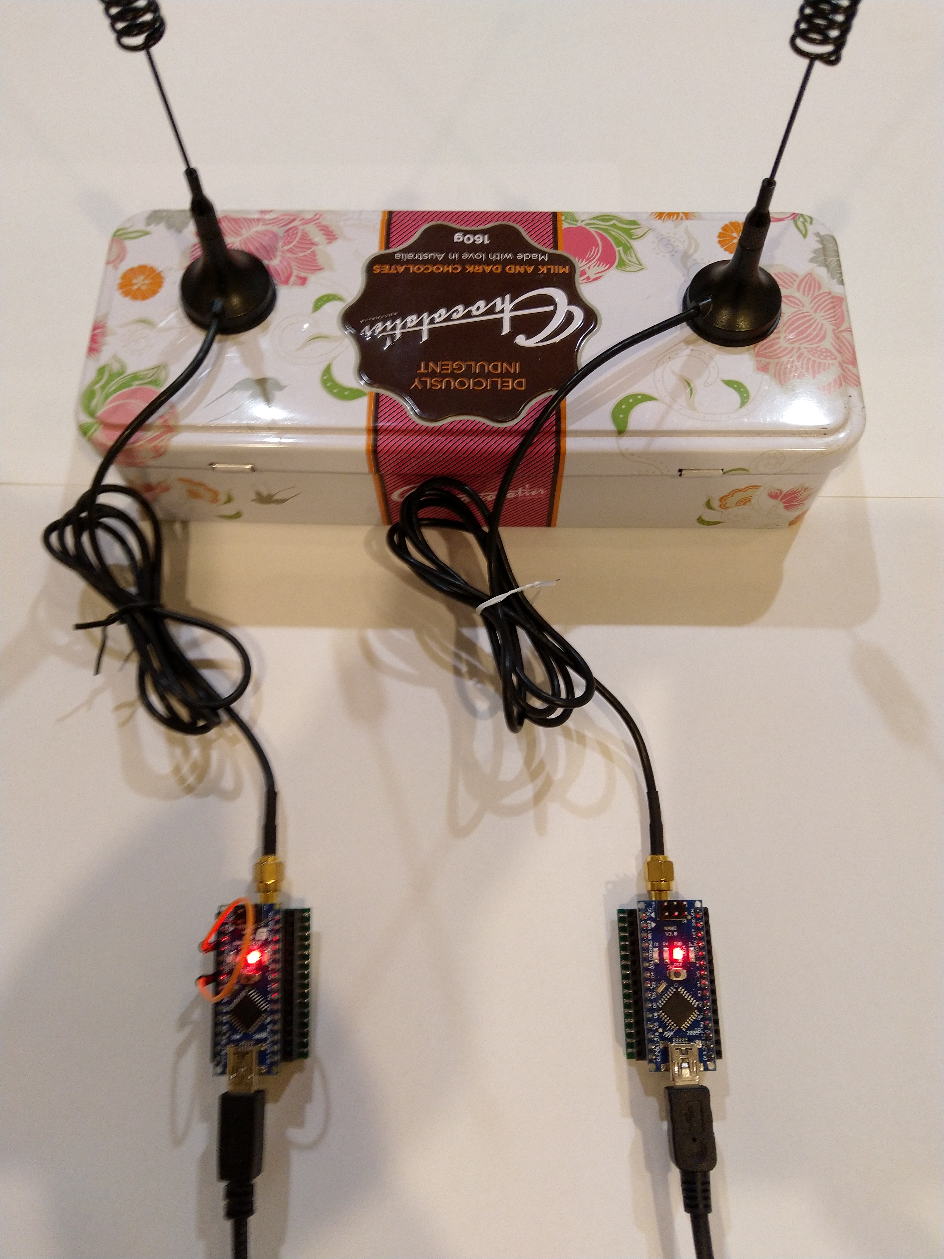
Arduino based transmit and receive test rig
I used the same Arduino devices and code as my receive and transmit samples. After sorting out the timing for enabling receive mode on the Windows 10IoT Core the transmission and receiving of packets was reliable (as long as two devices weren’t transmitting at the same time).
Byte Hex 0x00 0xc0 0xe4 0x00
Register dump
Register 0x00 - Value 0X00 - Bits 00000000
Register 0x01 - Value 0X04 - Bits 00000100
Register 0x02 - Value 0X00 - Bits 00000000
…
Register 0x3b - Value 0X00 - Bits 00000000
Register 0x3c - Value 0X0f - Bits 00001111
Register 0x3d - Value 0X02 - Bits 00000010
20:20:14.952 Send-Done
20:20:15.146 RegIrqFlags 00001000
20:20:15.160 Transmit-Done
20:20:15.298 RegIrqFlags 01000110
20:20:15 Received 14 byte message Hello world:89
20:20:17.429 RegIrqFlags 01000110
20:20:17 Received 14 byte message Hello world:90
The thread 0x1658 has exited with code 0 (0x0).
The thread 0x15cc has exited with code 0 (0x0).
20:20:19.560 RegIrqFlags 01000110
20:20:19 Received 14 byte message Hello world:91
20:20:20.031 Send-Done
20:20:20.178 RegIrqFlags 00001000
20:20:20.194 Transmit-Done
The above trace is from the Windows 10 IoT Core device as it transmits and receives messages.
The above trace is from the Arduino device configured to receive messages and it is receiving messages from the Windows 10 IoT Core device and the other Arduino.