Random wanderings through Microsoft Azure esp. PaaS plumbing, the IoT bits, AI on Micro controllers, AI on Edge Devices, .NET nanoFramework, .NET Core on *nix and ML.NET+ONNX
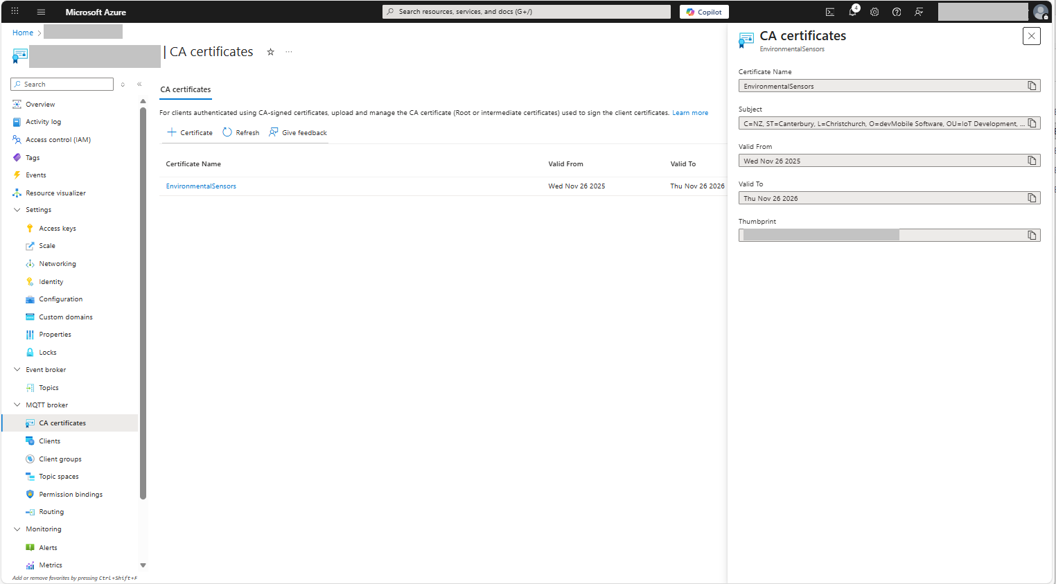
For a non-trivial system there should be a number of intermediate certificates. I have tried creating intermediate certificates for a device type, geography, application, customer and combinations of these. The first couple of times got it wrong so start with a field trial so that it isn’t so painful to go back and fix. (beware the sunk cost fallacy)
I found creating an intermediate certificate that could sign device certificates required a conf file for the basicConstraints and keyUsage configuration.
critical-The extension must be understood and processed by any application validating the certificate. If the application does not understand it, the certificate must be rejected.
CA:TRUE-This certificate is allowed to act as a Certificate Authority (CA), meaning it can sign other certificates.
pathlen:0-This CA can only issue end-entity (leaf) certificates and cannot issue further intermediate CA certificates.
keyCertSig- The certificate can be used to sign other certificates (i.e., it’s a CA certificate).
For production systems putting some thought into the Common name(CN), Organizational unit name(OU), Organization name(O), locality name(L), state or province name(S) and Country name(C)
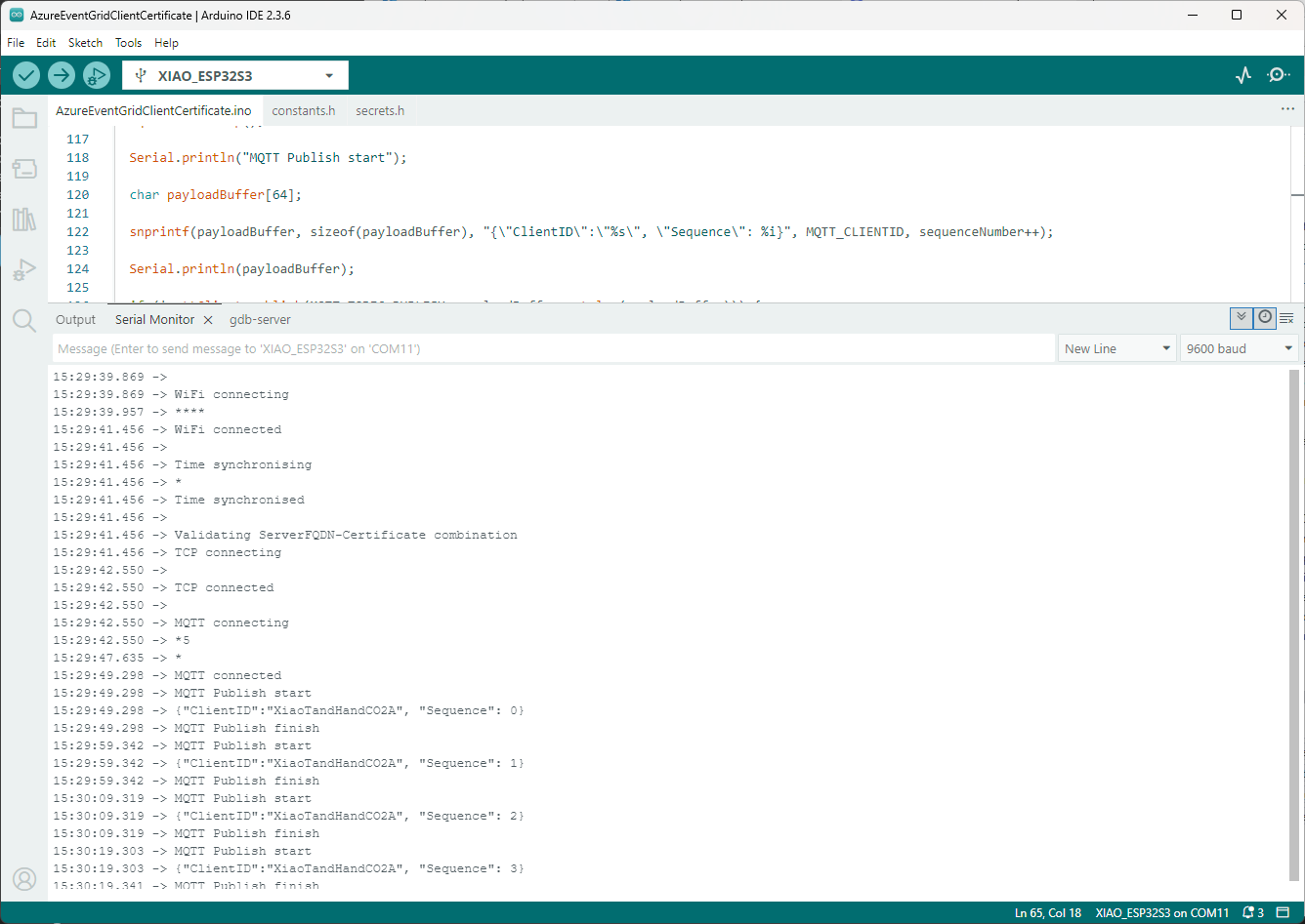
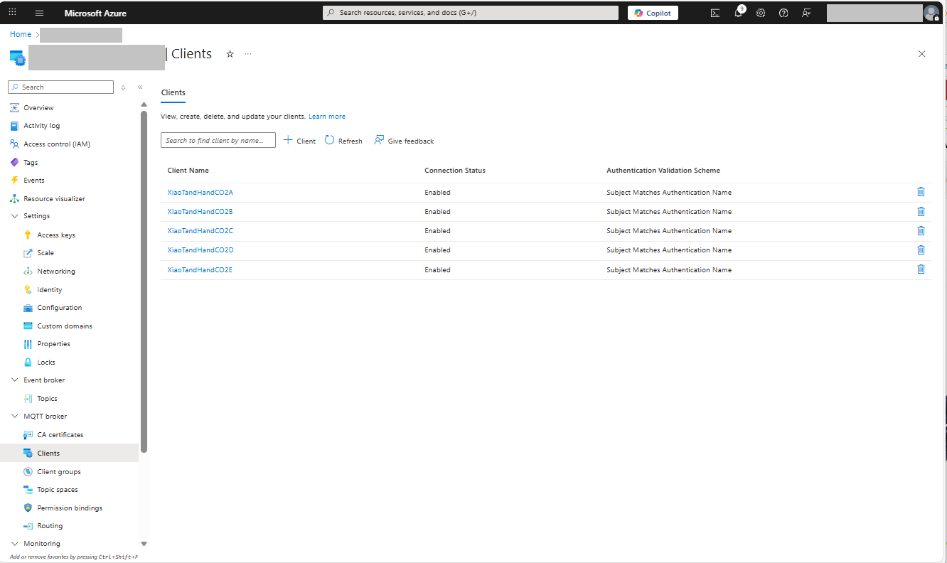
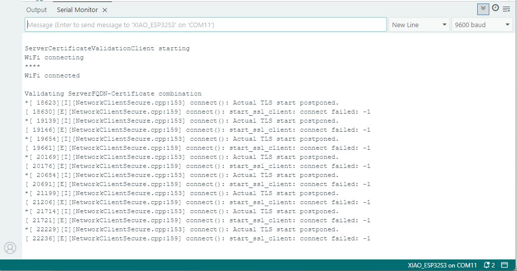
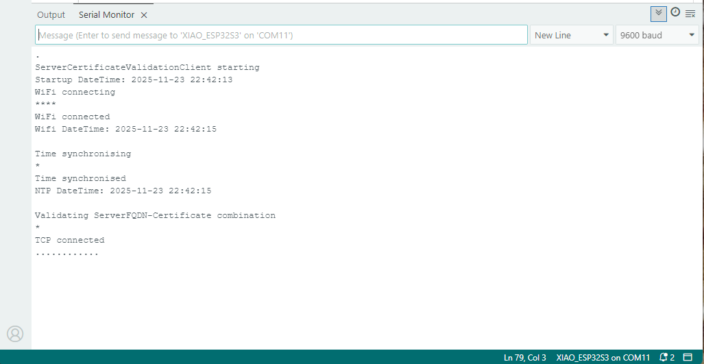
Establishing a connection to the Azure Event Grid MQTT broker often failed which surprised me. Initially I didn’t have any retry logic which meant I wasted quite a bit of time trying to debug failed connections
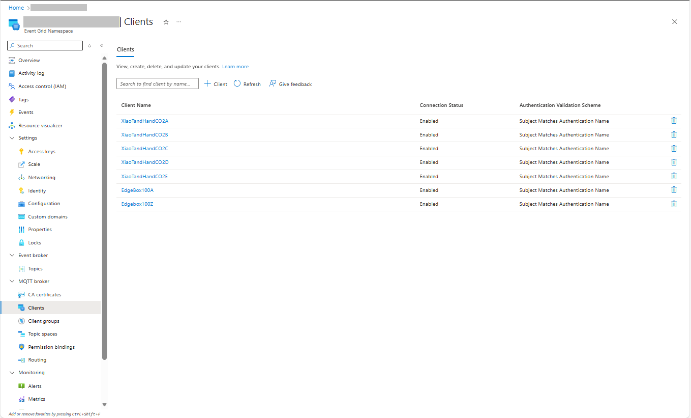
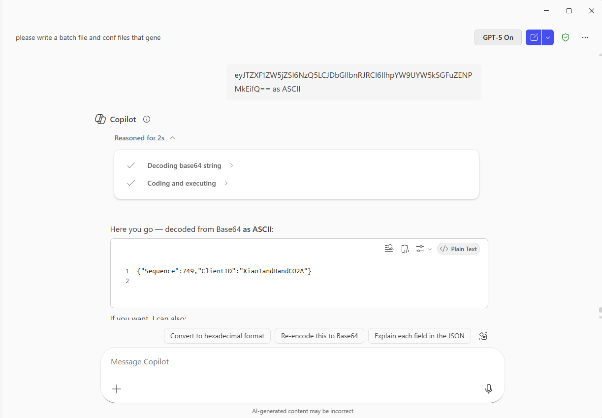
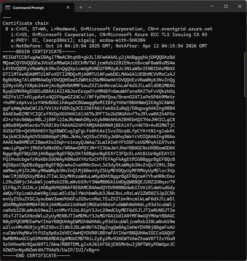
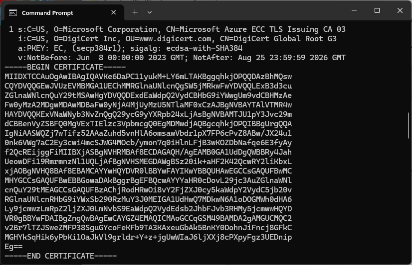
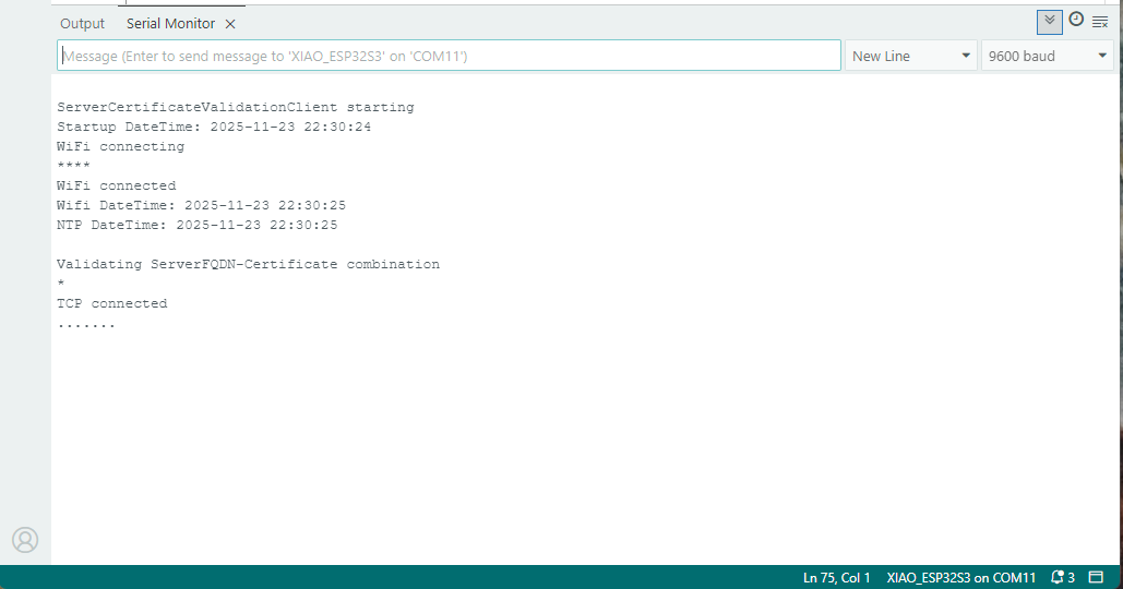
Over the last couple of weekends I had been trying to get a repeatable process for extracting the X509 certificate information in the correct structure so my Arduino application could connect to Azure Event Grid. The first step was to get the certificate chain for my Azure Event Grid MQTT Broker with openssl
The CN: CN=DigiCert Global Root G3 and the wildcard CN=*.eventgrid.azure.net certificates were “concatenated” in the constants header file which is included in the main program file. The format of the certificate chain is described in the comments. Avoid blank lines, “rogue” spaces or other formatting as these may cause the WiFiClientSecureMbed TLS implementation to fail.
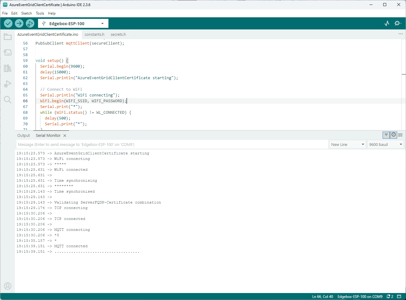
After a hard reset the WiFiClientSecure connect failed because the device time had not been initialised so the device/server time offset was too large (see rfc9325)
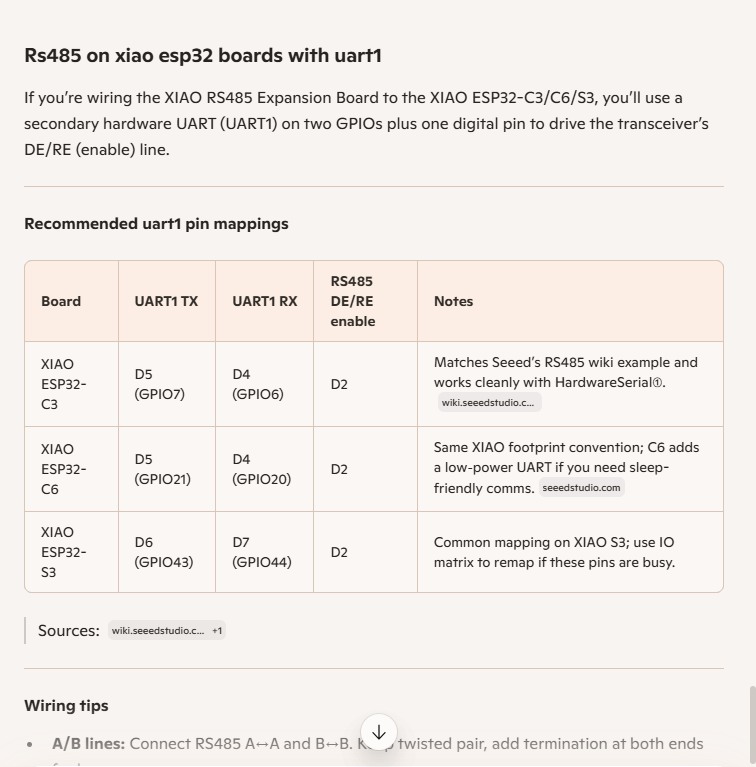
I then did some digging looked at schematics and figured out the port mappings were different. This took a while so I tried Microsoft Copilot
I then updated the port assigned for my RS485Sender application
#include <HardwareSerial.h>

HardwareSerial RS485(1);

#define enable_pin D2

void setup() {
  Serial.begin(9600);  // Initialize the hardware serial with a baud rate of 115200
  delay(5000);

  Serial.println("RS485 Sender");

  // Wait for the hardware serial to be ready
  while (!Serial)
    ;
  Serial.println("!Serial done");

  //mySerial.begin(115200, SERIAL_8N1, 7, 6); // RX=D4(GPIO6), TX=D5(GPIO7) Doesn't work
  RS485.begin(115200, SERIAL_8N1, 6, 5);

  // Wait for the hardware serial to be ready
  while (!RS485)
    ;
  Serial.println("!RS485 done ");

  pinMode(enable_pin, OUTPUT);     // Set the enable pin as an output
  digitalWrite(enable_pin, HIGH);  // Set the enable pin to high
}

void loop() {
  if (Serial.available()) {
    String inputData = Serial.readStringUntil('\n');  // Read the data from the hardware serial until a newline character

    // If the received data is not empty
    if (inputData.length() > 0) {
      Serial.println("Send successfully");  // Print a success message
      RS485.println(inputData);             // Send the received data to the hardware serial
    }
  }
}
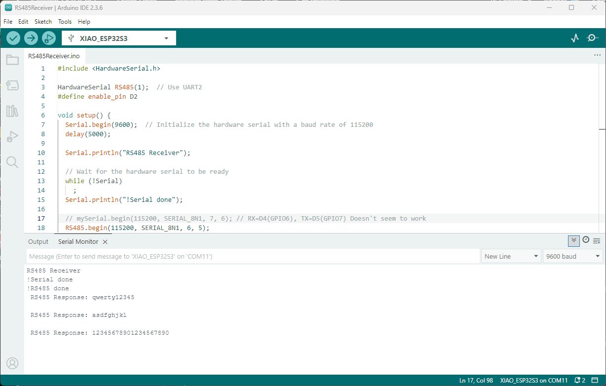
I then updated the port assigned for my RS485Receiver application
#include <HardwareSerial.h>

HardwareSerial RS485(1);  // Use UART2
#define enable_pin D2

void setup() {
  Serial.begin(9600);  // Initialize the hardware serial with a baud rate of 115200
  delay(5000);

  Serial.println("RS485 Receiver");

  // Wait for the hardware serial to be ready
  while (!Serial)
    ;
  Serial.println("!Serial done");

  // mySerial.begin(115200, SERIAL_8N1, 7, 6); // RX=D4(GPIO6), TX=D5(GPIO7) Doesn't seem to work
  RS485.begin(115200, SERIAL_8N1, 6, 5);

    // Wait for the hardware serial to be ready
  while (!RS485)
    ;
  Serial.println("!RS485 done ");

  pinMode(enable_pin, OUTPUT);    // Set the enable pin as an output
  digitalWrite(enable_pin, LOW);  // Set the enable pin to low
}

void loop() {
  // Check if there is data available from the hardware serial
  int x = RS485.available();

  if (x) {
    String response = RS485.readString();

    Serial.println(" RS485 Response: " + response);
  }

  delay(1000);
}
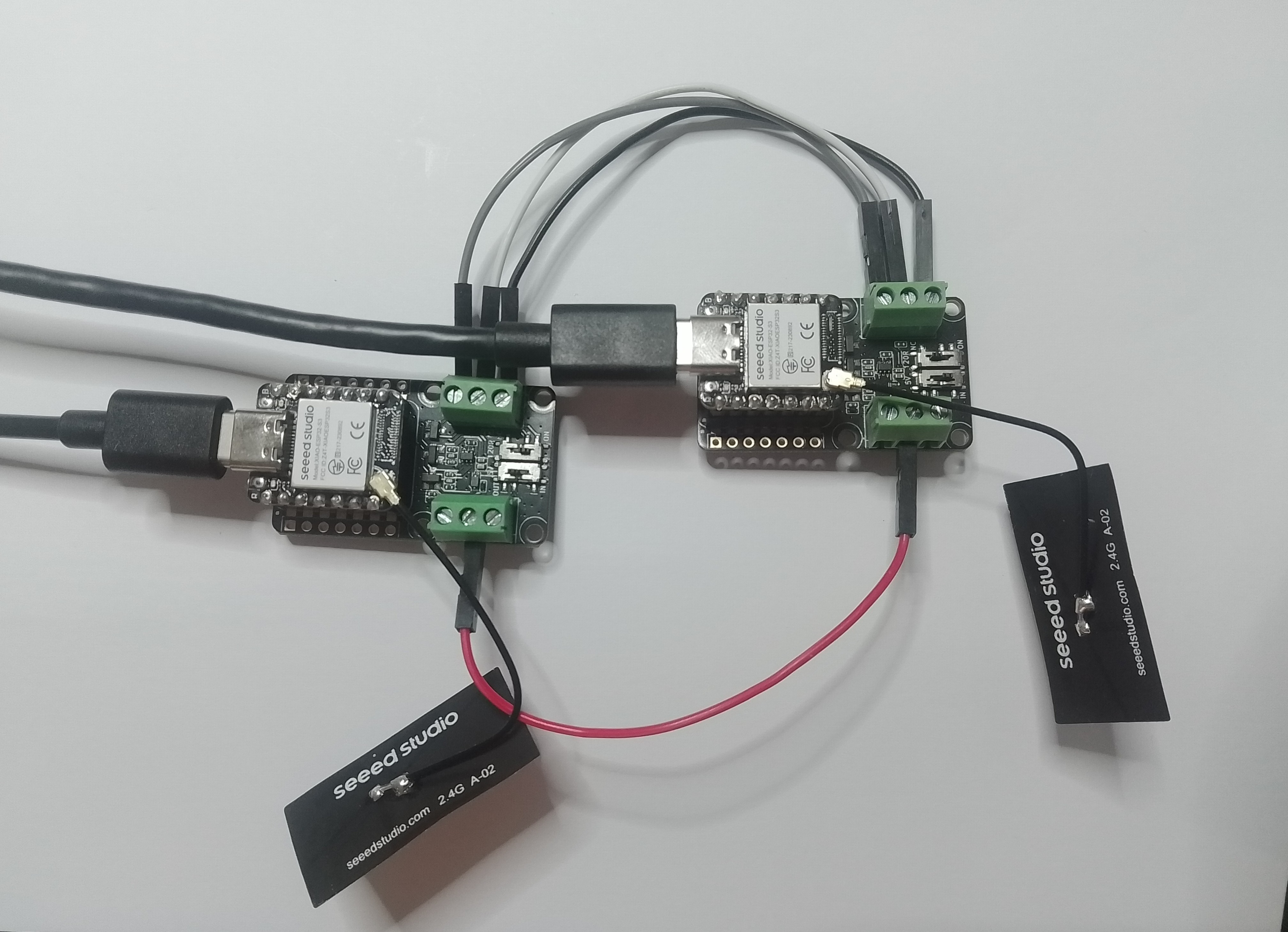
Getting my test harness RS485Sender and RS485Receiver applications (inspired by Seeedstudio wiki) took quite a bit longer than expected. Using Copilot worked better than expected but I think that might be because after doing some research my prompts were better.
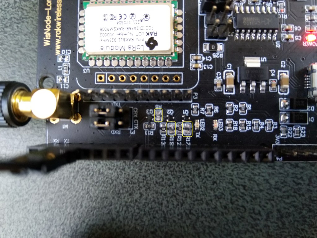
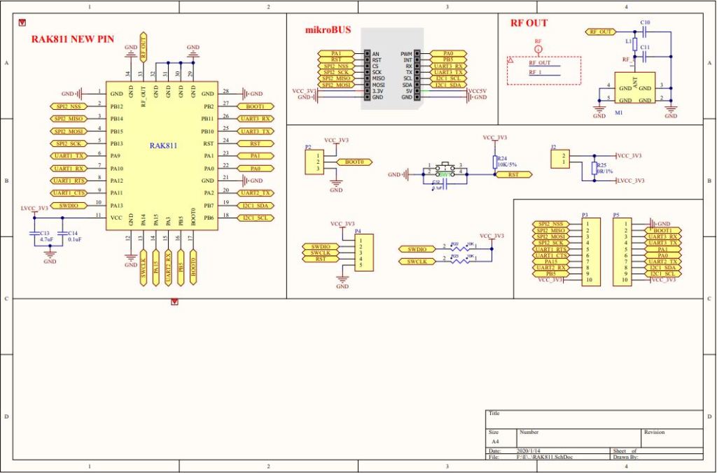
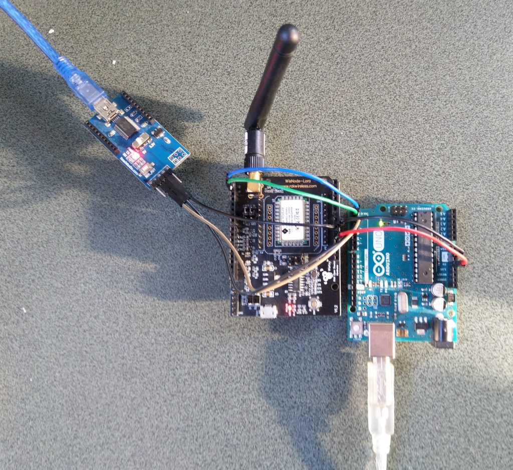
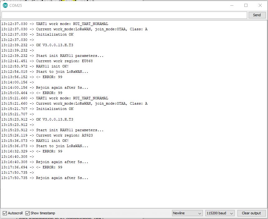
I wanted the RAK811 LPWAN Evaluation Board(EVB) -AS923 to work with selection of my Arduino and nanoFramework devices. The first decision was which of the hardware serial port (D0,D1) or the software serial port (D10,D11) should be connected to P1?
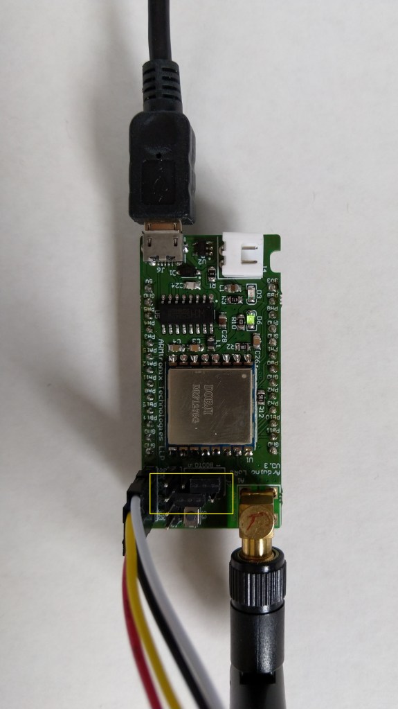
To use the EVB with my STM32F691DISCOVERY board running the nanoFramework (COM5 on the hardware serial port pins D0,D1) I removed R17&R19.
After some tinkering, I found that R8 which is connected to the RAK811 module reset had to be cut as well for the shield to work on my Arduino Uno R3 and STM32F691DISCOVERY devices.
RAK811 EVB with R17,R19 & R8 cut
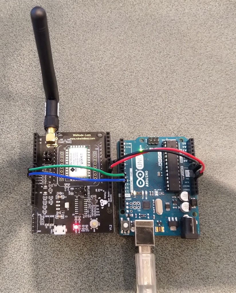
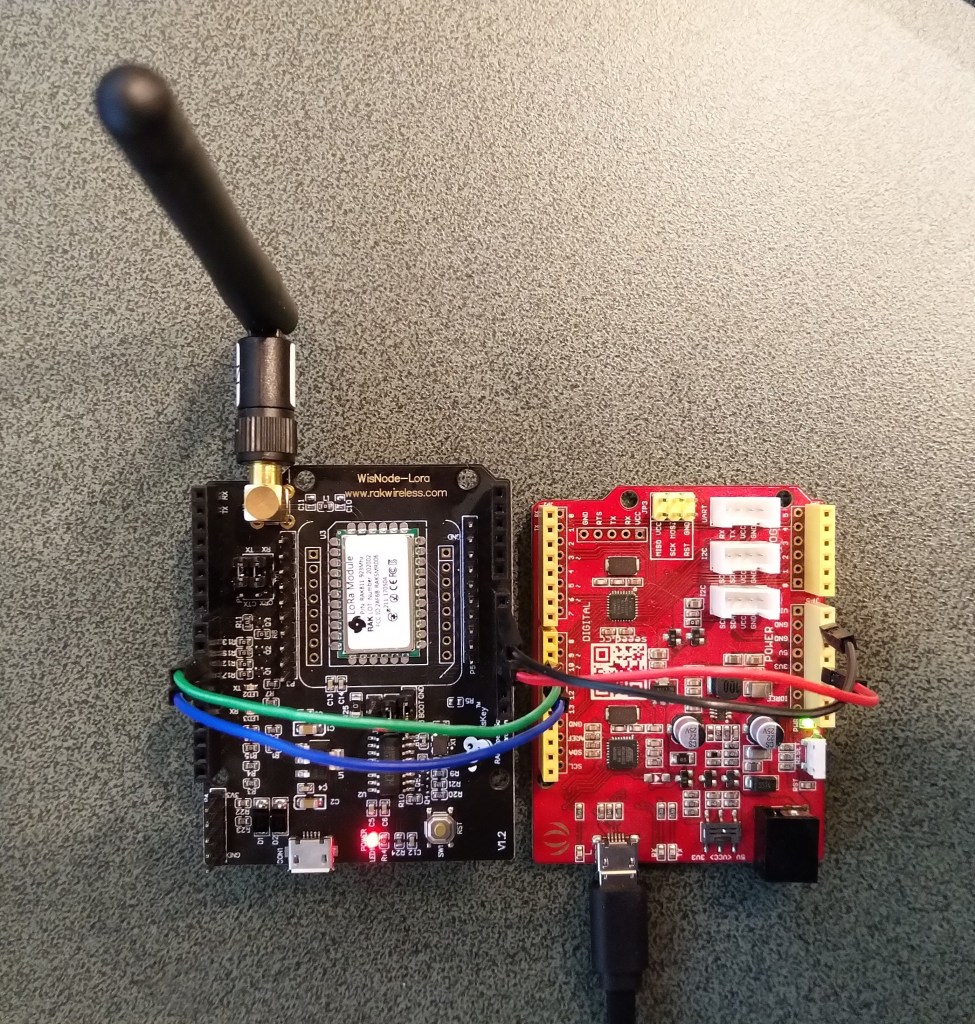
I can still run the Arduino Uno R3 and RAK811 EVB in the original configuration with a couple of jumper leads
RAK811 on Arduino with Serial connected to D10,D1 a SoftwareSerial port
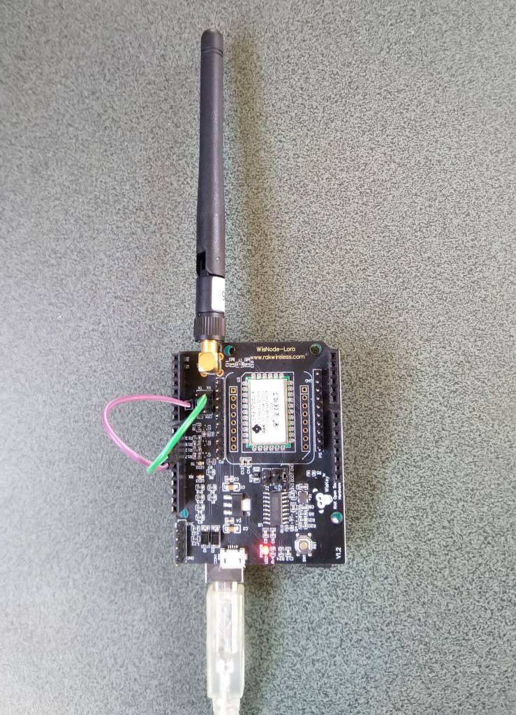
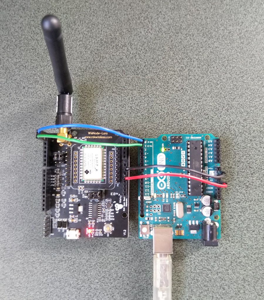
For devices where I needed D10,D11 for a Serial Peripheral Interface(SPI) I could use an FTDI board and a couple of other pins (in this case D2,D3) for serial logging.
RAK811 on Arduino with Serial connected to D2,D2 a SoftwareSerial port
After debugging some code I also replaced the small jumpers on P1 with a couple of jumper leads so it was less fiddly to swap from downloading to debugging.
Just over a week ago I purchased a RAK811 LPWAN Evaluation Board -AS923 and now I want to trial it with selection of devices and configurations.
Initially I didn’t want to modify the shield by removing resistors as I only have one, and I’m not certain what device(s) it will be used with. The initial hardware configuration required jumpers for the serial port, ground and 5V power.
Arduino Uno R3 and RAK811 LPWAN Evaluation board 5V config
After looking at the schematic it should be possible to use the shield with a 3v3 device.
RAK 811 EVB schematic pg1RAK 811 EVB schematic pg2
I confirmed this with a Seeeduino V4.2 devices set to 3v3, by putting a jumper on J1 and shifting the jumper wire from the 5V to the 3V3 pin.
Seeeduino V4 and RAK811 LPWAN Evaluation board 3V3 config
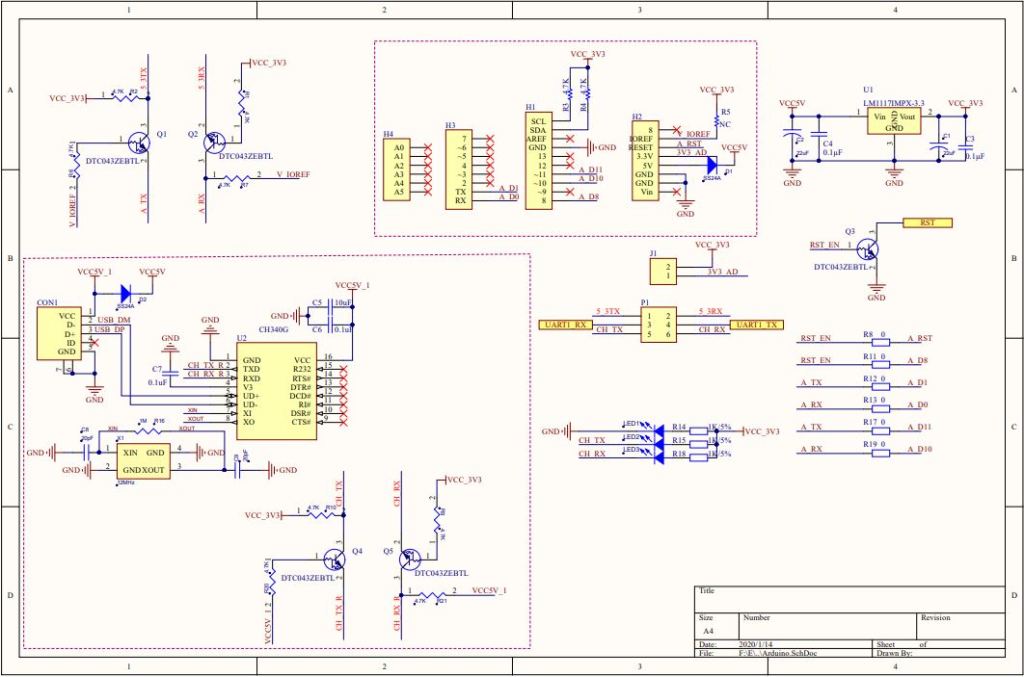
The next step was to see how I could get the RAK shield working on other devices without jumpers. On Arduino Uno R3 devices D0&D1 are the hardware(HW) serial port which are used for uploading sketches, and diagnostic logging.
The shield also connects the module serial port to D0&D1 to D10&D11, so by removing R17&R19 the shield should work on a device This would also allow the use of the Serial Peripheral Interface(SPI) port for other applications.
Using the HW Serial port but without any logging.
Unplugging the jumpers to upload was painful but the lack of logging made it really hard to debug my code.
To get around this I configured a SoftwareSerial port on D2&D3 for logging.
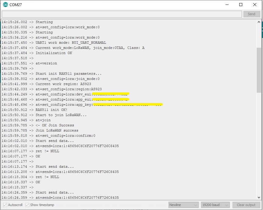
/********************************************************
* This demo is only supported after RUI firmware version 3.0.0.13.X on RAK811
* Master Board Uart Receive buffer size at least 128 bytes.
********************************************************/
//#define SERIAL_BUFFER_SIZE 128
//#define SERIAL_TX_BUFFER_SIZE 64
//#define SERIAL_RX_BUFFER_SIZE 128
//#define _SS_MAX_RX_BUFF 128
#include "RAK811.h"
#include "SoftwareSerial.h"
#define WORK_MODE LoRaWAN // LoRaWAN or LoRaP2P
#define JOIN_MODE OTAA // OTAA or ABP
#if JOIN_MODE == OTAA
String DevEui = "..."; // From TTN
String AppEui = "...";
String AppKey = "...";
#else JOIN_MODE == ABP
String NwkSKey = "...";
String AppSKey = "...";
String DevAddr = "...";
#endif
#define TXpin 3 // Set the virtual serial port pins
#define RXpin 2
SoftwareSerial DebugSerial(RXpin,TXpin); // Declare a virtual serial port for debugging
#define ATSerial Serial
char buffer[]= "48656C6C6F20776F726C6435";
bool InitLoRaWAN(void);
RAK811 RAKLoRa(ATSerial,DebugSerial);
void setup() {
DebugSerial.begin(19200);
DebugSerial.println(F("Starting"));
while(DebugSerial.available())
{
DebugSerial.read();
}
ATSerial.begin(9600); //set ATSerial baudrate:This baud rate has to be consistent with the baud rate of the WisNode device.
while(ATSerial.available())
{
ATSerial.read();
}
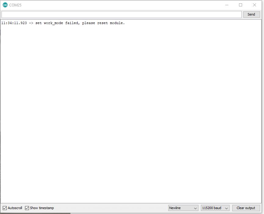
if(!RAKLoRa.rk_setWorkingMode(0)) //set WisNode work_mode to LoRaWAN.
{
DebugSerial.println(F("set work_mode failed, please reset module."));
while(1);
}
RAKLoRa.rk_getVersion(); //get RAK811 firmware version
DebugSerial.println(RAKLoRa.rk_recvData()); //print version number
DebugSerial.println(F("Start init RAK811 parameters..."));
if (!InitLoRaWAN()) //init LoRaWAN
{
DebugSerial.println(F("Init error,please reset module."));
while(1);
}
DebugSerial.println(F("Start to join LoRaWAN..."));
while(!RAKLoRa.rk_joinLoRaNetwork(60)) //Joining LoRaNetwork timeout 60s
{
DebugSerial.println();
DebugSerial.println(F("Rejoin again after 5s..."));
delay(5000);
}
DebugSerial.println(F("Join LoRaWAN success"));
if(!RAKLoRa.rk_isConfirm(0)) //set LoRa data send package type:0->unconfirm, 1->confirm
{
DebugSerial.println(F("LoRa data send package set error,please reset module."));
while(1);
}
}
bool InitLoRaWAN(void)
{
if(RAKLoRa.rk_setJoinMode(JOIN_MODE)) //set join_mode:OTAA
{
if(RAKLoRa.rk_setRegion(0)) //set region EU868
{
if (RAKLoRa.rk_initOTAA(DevEui, AppEui, AppKey))
{
DebugSerial.println(F("RAK811 init OK!"));
return true;
}
}
}
return false;
}
void loop()
{
DebugSerial.println(F("Start send data..."));
if (RAKLoRa.rk_sendData(1, buffer))
{
//for (unsigned long start = millis(); millis() - start < 300000L;)
for (unsigned long start = millis(); millis() - start < 10000L;)
{
String ret = RAKLoRa.rk_recvData();
if(ret != NULL)
{
DebugSerial.println("ret != NULL");
DebugSerial.println(ret);
}
if((ret.indexOf("OK")>0)||(ret.indexOf("ERROR")>0))
{
DebugSerial.println(F("Go to Sleep."));
RAKLoRa.rk_sleep(1); //Set RAK811 enter sleep mode
delay(10000); //delay 10s
RAKLoRa.rk_sleep(0); //Wakeup RAK811 from sleep mode
break;
}
}
}
}
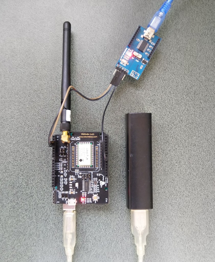
I used an FTDI module I had lying around to connect the diagnostic logging serial port on the test rig to my development box.
Using the HW Serial port but with logging.
Now I only had to unplug the jumpers for D0&D1 and change ports in the Arduino IDE. One port for debugging the other for downloading.
Depending on the application I may remove R8 so I can manually reset the shield.
The evaluation board was in its own box along with a USB cable, some spare PCB jumpers, some jumper leads and an antenna labeled with the frequency band which was thoughtful.
Arduino Uno R3 and RAK811 LPWAN Evaluation board 5V config
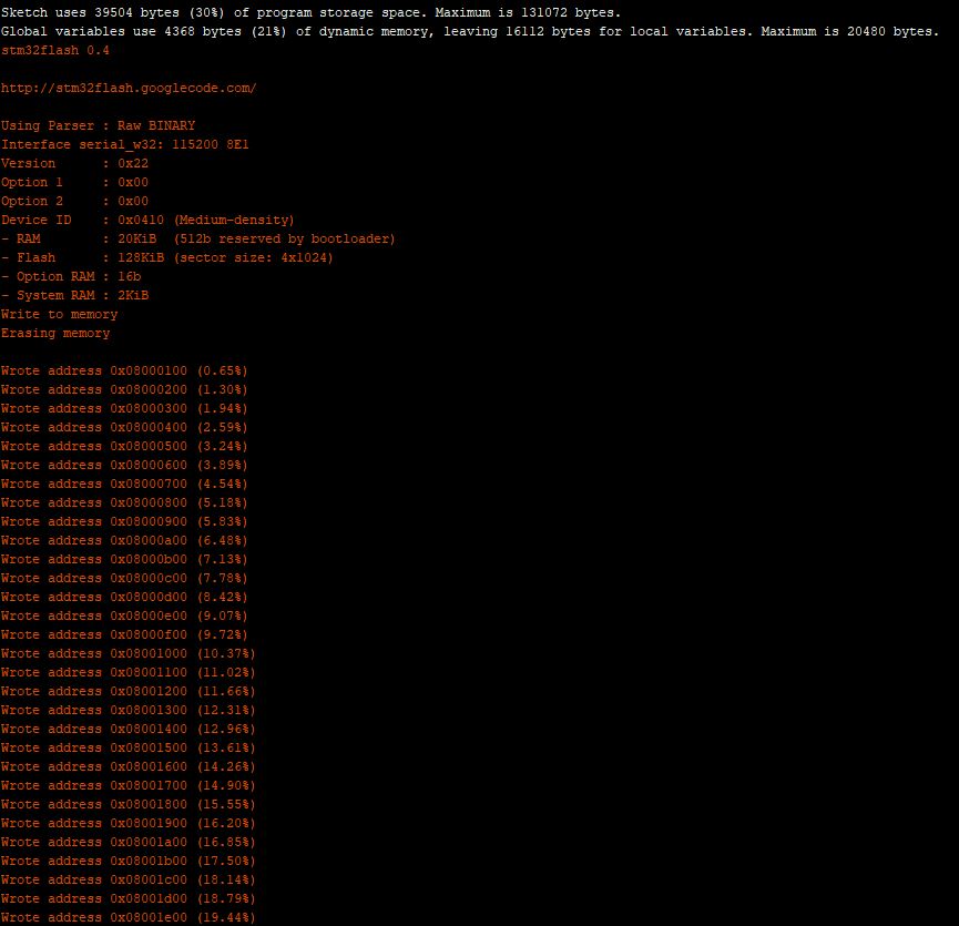
I downloaded the specified library from the RAK Wireless Github repository extracted the contents and copied the V1.3 directory into the libraries folder of my Arduino IDE install.
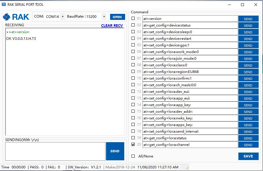
I updated the module software to the latest using the tools provided in the github download and checked this with the RAK Serial Port tool over the Universal Serial Bus(USB) connection (make sure the jumpers next to the antenna connection are set correctly)
I then had a look at the Arduino library code and enabled some of the commented out diagnostic println statements. At the time it did seem odd there were no responses from the module.
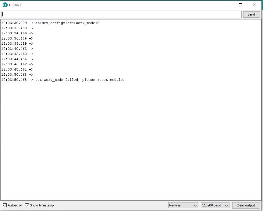
Arduino monitor output showing rk_setWorkingMode failing with debugging
I had noticed some odd characters in the RAK Serial Port Tool while checking version numbers etc.
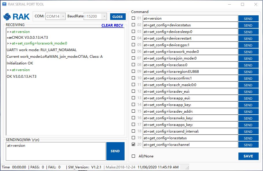
Setting work Mode with RAK Serial Port Tool
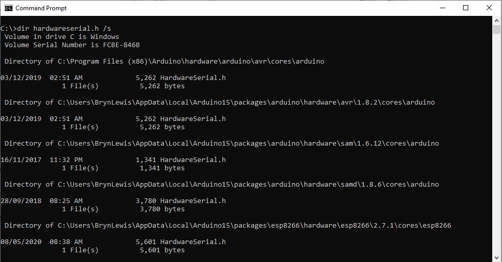
It looked like maybe the serial port was having some issues, so I double checked my modification of the HardwareSerial.h file and began to wonder (as the binary size wasn’t changing) if I had the right file. After some research I found there are several copies of that file and I wasn’t modifying the correct one.
Multiple locations of HardwareSerial.h
Then I realised that the port sending AT Commands to the module was actually a SoftwareSerial port not a hardware one. I then tried changing the size of the software serial buffers but still was having problems.
Arduino tool with default buffer sizes (833 bytes)Arduino tool with non-default buffer sizes (961 bytes)
I then tried recompiling with different settings to see if the serial port issues would stop. The global variables size changed which showed I had the right files/settings but the code still didn’t work.
Going back over my settings I tried the command used in the rk_setWorkingMode call in the RAK Serial Port Tool and it worked.
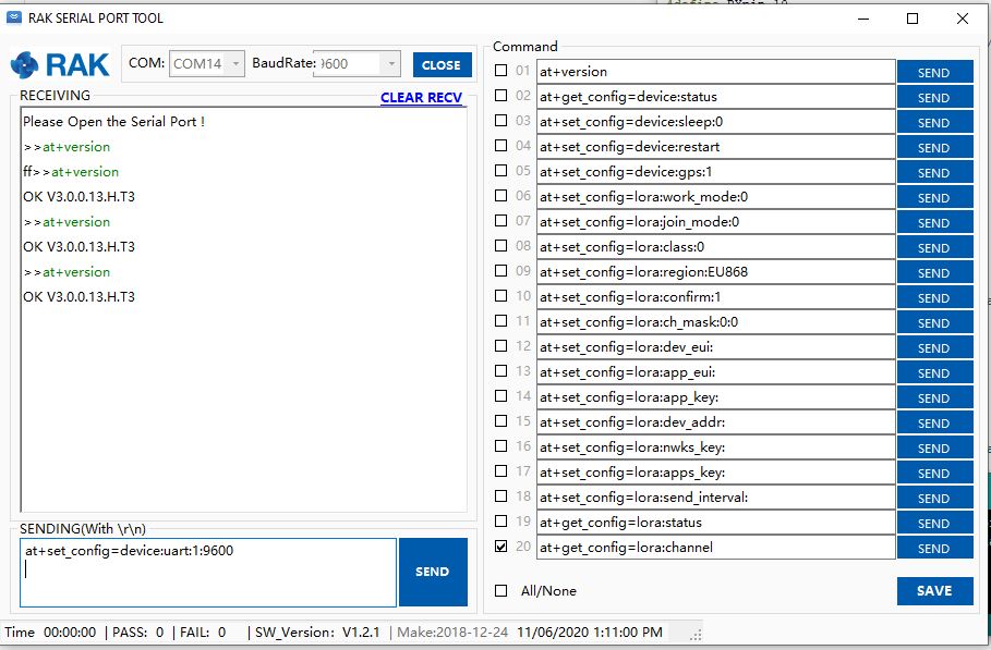
I then then went for a walk and when I came back I realised the module speed was set to 115200 baud by default (which it is). I then used at+set_config=device:uart:1:9600 (don’t forget to press <enter> at end of the line) to set baud rate to match the code.
Setting device to 9600 baud
I then changed the jumpers and ran the software again…
So, it looks like the RAK811 module was set to 115200 baud (web based setup instructions), but the later library versions were 9600 baud, but the instructions didn’t mention the need to change the speed with the RAK Serial port tool.
Image of code and setup from RAK instructions
Now that my device is trying to connect to a network I need to configure the LoRaWAN network settings. I’m going to use the RAK7246G LPWAN Developer Gateway and the nationwide LoRaWAN network operated by Spark in New Zealand.
Grove – 4 pin Female Jumper to Grove 4 pin Conversion Cable USD3.90
Armtronix device with Seeedstudio temperature & humidity sensor
I used a modified version of my Arduino client code which worked after I got the pins sorted and the female jumper sockets in the right order.
/*
  Copyright ® 2019 December devMobile Software, All Rights Reserved

  THIS CODE AND INFORMATION IS PROVIDED "AS IS" WITHOUT WARRANTY OF ANY
  KIND, EITHER EXPRESSED OR IMPLIED, INCLUDING BUT NOT LIMITED TO THE
  IMPLIED WARRANTIES OF MERCHANTABILITY AND/OR FITNESS FOR A PARTICULAR
  PURPOSE.

  You can do what you want with this code, acknowledgment would be nice.

  http://www.devmobile.co.nz

*/
#include <stdlib.h>
#include <LoRa.h>
#include <TH02_dev.h>

//#define DEBUG
//#define DEBUG_TELEMETRY
//#define DEBUG_LORA

// LoRa field gateway configuration (these settings must match your field gateway)
const char FieldGatewayAddress[] = {"LoRaIoT1"};
const char DeviceAddress[] = {"ArmTronix01"};
const float FieldGatewayFrequency =  915000000.0;
const byte FieldGatewaySyncWord = 0x12 ;

// Payload configuration
const int ChipSelectPin = PA4;
const int InterruptPin = PA11;
const int ResetPin = PC13;

// LoRa radio payload configuration
const byte SensorIdValueSeperator = ' ' ;
const byte SensorReadingSeperator = ',' ;
const int LoopSleepDelaySeconds = 30 ;

const byte PayloadSizeMaximum = 64 ;
byte payload[PayloadSizeMaximum];
byte payloadLength = 0 ;


void setup()
{
  Serial.begin(9600);
#ifdef DEBUG
  while (!Serial);
#endif
  Serial.println("Setup called");

  Serial.println("LoRa setup start");

  // override the default chip select and reset pins
  LoRa.setPins(ChipSelectPin, ResetPin, InterruptPin);
  if (!LoRa.begin(FieldGatewayFrequency))
  {
    Serial.println("LoRa begin failed");
    while (true); // Drop into endless loop requiring restart
  }

  // Need to do this so field gateways pays attention to messsages from this device
  LoRa.enableCrc();
  LoRa.setSyncWord(FieldGatewaySyncWord);

#ifdef DEBUG_LORA
  LoRa.dumpRegisters(Serial);
#endif
  Serial.println("LoRa Setup done.");

  // Configure the Seeedstudio TH02 temperature & humidity sensor
  Serial.println("TH02 setup start");
  TH02.begin();
  delay(100);
  Serial.println("TH02 setup done");

  PayloadHeader((byte*)FieldGatewayAddress,strlen(FieldGatewayAddress), (byte*)DeviceAddress, strlen(DeviceAddress));

  Serial.println("Setup done");
  Serial.println();
}


void loop()
{
  float temperature ;
  float humidity ;

  Serial.println("Loop called");

  PayloadReset();

  // Read the temperature & humidity & battery voltage values then display nicely
  temperature = TH02.ReadTemperature();
  Serial.print("T:");
  Serial.print( temperature, 1 ) ;
  Serial.println( "C " ) ;

  PayloadAdd( "T", temperature, 1);

  humidity = TH02.ReadHumidity();
  Serial.print("H:");
  Serial.print( humidity, 0 ) ;
  Serial.println( "% " ) ;

  PayloadAdd( "H", humidity, 0) ;

#ifdef DEBUG_TELEMETRY
  Serial.print( "RFM9X/SX127X Payload len:");
  Serial.print( payloadLength );
  Serial.println( " bytes" );
#endif

  LoRa.beginPacket();
  LoRa.write( payload, payloadLength );
  LoRa.endPacket();

  Serial.println("Loop done");
  Serial.println();
  delay(LoopSleepDelaySeconds * 1000l);
}


void PayloadHeader( byte *to, byte toAddressLength, byte *from, byte fromAddressLength)
{
  byte addressesLength = toAddressLength + fromAddressLength ;

#ifdef DEBUG_TELEMETRY
  Serial.print("PayloadHeader- ");
  Serial.print( "To len:");
  Serial.print( toAddressLength );
  Serial.print( " From len:");
  Serial.print( fromAddressLength );
  Serial.print( " Header len:");
  Serial.print( addressesLength );
  Serial.println( );
#endif

  payloadLength = 0 ;

  // prepare the payload header with "To" Address length (top nibble) and "From" address length (bottom nibble)
  payload[payloadLength] = (toAddressLength << 4) | fromAddressLength ;
  payloadLength += 1;

  // Copy the "To" address into payload
  memcpy(&payload[payloadLength], to, toAddressLength);
  payloadLength += toAddressLength ;

  // Copy the "From" into payload
  memcpy(&payload[payloadLength], from, fromAddressLength);
  payloadLength += fromAddressLength ;
}


void PayloadAdd( const char *sensorId, float value, byte decimalPlaces)
{
  byte sensorIdLength = strlen( sensorId ) ;

#ifdef DEBUG_TELEMETRY
  Serial.print("PayloadAdd-float ");
  Serial.print( "SensorId:");
  Serial.print( sensorId );
  Serial.print( " Len:");
  Serial.print( sensorIdLength );
  Serial.print( " Value:");
  Serial.print( value, decimalPlaces );
  Serial.print( " payloadLen:");
  Serial.print( payloadLength);
#endif

  memcpy( &payload[payloadLength], sensorId,  sensorIdLength) ;
  payloadLength += sensorIdLength ;
  payload[ payloadLength] = SensorIdValueSeperator;
  payloadLength += 1 ;
  payloadLength += strlen( dtostrf(value, -1, decimalPlaces, (char *)&payload[payloadLength]));
  payload[ payloadLength] = SensorReadingSeperator;
  payloadLength += 1 ;

#ifdef DEBUG_TELEMETRY
  Serial.print( " payloadLen:");
  Serial.println( payloadLength);
#endif
}


void PayloadAdd( const char *sensorId, int value )
{
  byte sensorIdLength = strlen( sensorId ) ;

#ifdef DEBUG_TELEMETRY
  Serial.print("PayloadAdd-int ");
  Serial.print( "SensorId:");
  Serial.print( sensorId );
  Serial.print( " Len:");
  Serial.print( sensorIdLength );
  Serial.print( " Value:");
  Serial.print( value );
  Serial.print( " payloadLen:");
  Serial.print( payloadLength);
#endif

  memcpy( &payload[payloadLength], sensorId,  sensorIdLength) ;
  payloadLength += sensorIdLength ;
  payload[ payloadLength] = SensorIdValueSeperator;
  payloadLength += 1 ;
  payloadLength += strlen( itoa( value,(char *)&payload[payloadLength],10));
  payload[ payloadLength] = SensorReadingSeperator;
  payloadLength += 1 ;

#ifdef DEBUG_TELEMETRY
  Serial.print( " payloadLen:");
  Serial.println( payloadLength);
#endif
}


void PayloadAdd( const char *sensorId, unsigned int value )
{
  byte sensorIdLength = strlen( sensorId ) ;

#ifdef DEBUG_TELEMETRY
  Serial.print("PayloadAdd-unsigned int ");
  Serial.print( "SensorId:");
  Serial.print( sensorId );
  Serial.print( " Len:");
  Serial.print( sensorIdLength );
  Serial.print( " Value:");
  Serial.print( value );
  Serial.print( " payloadLen:");
  Serial.print( payloadLength);
#endif

  memcpy( &payload[payloadLength], sensorId,  sensorIdLength) ;
  payloadLength += sensorIdLength ;
  payload[ payloadLength] = SensorIdValueSeperator;
  payloadLength += 1 ;
  payloadLength += strlen( utoa( value,(char *)&payload[payloadLength],10));
  payload[ payloadLength] = SensorReadingSeperator;
  payloadLength += 1 ;

#ifdef DEBUG_TELEMETRY
  Serial.print( " payloadLen:");
  Serial.println( payloadLength);
#endif
}


void PayloadReset()
{
  byte fromAddressLength = payload[0] & 0xf ;
  byte toAddressLength = payload[0] >> 4 ;
  byte addressesLength = toAddressLength + fromAddressLength ;

  payloadLength = addressesLength + 1;

#ifdef DEBUG_TELEMETRY
  Serial.print("PayloadReset- ");
  Serial.print( "To len:");
  Serial.print( toAddressLength );
  Serial.print( " From len:");
  Serial.print( fromAddressLength );
  Serial.print( " Header len:");
  Serial.println( addressesLength );
#endif
}
To get the application to download I had to configure the board in the Arduino IDE
Then change the jumpers
Initially I had some problems deploying my software because I hadn’t followed the instructions (the wiki everyone referred to appeared to be offline) and run the installation batch file (New dev machine since my previous maple based project).
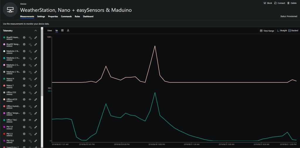
I configured the device to upload to my Azure IoT Hub/Azure IoT Central gateway and it has been running reliably for a couple of days.
Azure IoT Central temperature and humidity values
Initially I had some configuration problems but I contacted Armtronix support and they promptly provided a couple of updated links for product and device documentation.
Sample hardwareAzure IoT Central data visualisation
The Maduino device in the picture is a custom version with an onboard Microchip ATSHA204 crypto and authentication chip (currently only use for the unique 72 bit serial number) and a voltage divider connected to the analog pin A6 to monitor the battery voltage.
There are compile time options ATSHA204 & BATTERY_VOLTAGE_MONITOR which can be used to selectively enable this functionality.
I use the Arduino lowpower library to aggressively sleep the device between measurements
// Adjust the delay so period is close to desired sec as possible, first do 8sec chunks.
  int delayCounter = SensorUploadDelay / 8 ;
  for( int i = 0 ; i < delayCounter ; i++ )
  {
     LowPower.powerDown(SLEEP_8S, ADC_OFF, BOD_OFF);
  }

  // Then to 4 sec chunk
  delayCounter =  ( SensorUploadDelay % 8 ) / 4;
  for( int i = 0 ; i < delayCounter ; i++ )
  {
     LowPower.powerDown(SLEEP_4S, ADC_OFF, BOD_OFF);
  }

  // Then to 2 sec chunk
  delayCounter =  ( SensorUploadDelay % 4 ) / 2 ;
  for( int i = 0 ; i < delayCounter ; i++ )
  {
     LowPower.powerDown(SLEEP_2S, ADC_OFF, BOD_OFF);
  }

  // Then to 1 sec chunk
  delayCounter =  ( SensorUploadDelay % 2 ) ;
  for( int i = 0 ; i < delayCounter ; i++ )
  {
     LowPower.powerDown(SLEEP_1S, ADC_OFF, BOD_OFF);
  }
}
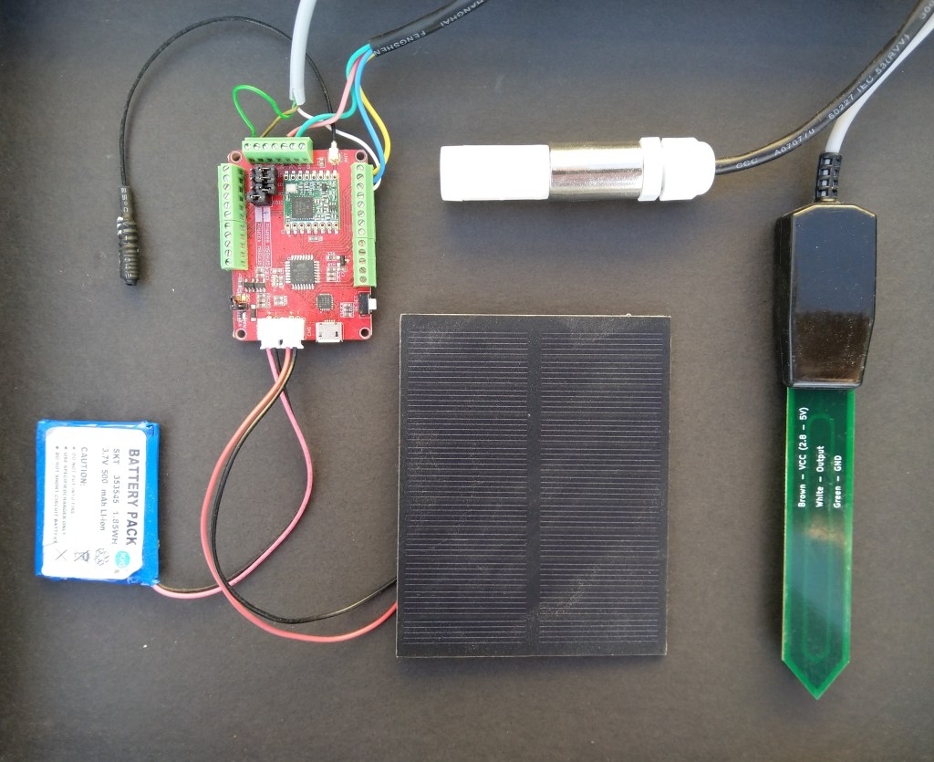
I use a spare digital PIN for powering the soil moisture probe so it can be powered down when not in use. I have included a short delay after powering up the device to allow the reading to settle.
  // Turn on soil mosture sensor, take reading then turn off to save power
  digitalWrite(SoilMoistureSensorEnablePin, HIGH);
  delay(SoilMoistureSensorEnableDelay);
  int soilMoistureADCValue = analogRead(SoilMoistureSensorPin);
  digitalWrite(SoilMoistureSensorEnablePin, LOW);
  int soilMoisture = map(soilMoistureADCValue,SoilMoistureSensorMinimum,SoilMoistureSensorMaximum, SoilMoistureValueMinimum, SoilMoistureValueMaximum);
  PayloadAdd( "s", soilMoisture, false);
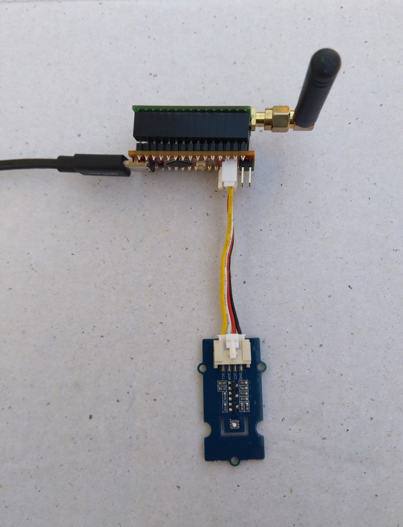
Seeeduino Nano easySensors shield and Grove VOC & eCO2 Sensor
Seeeduino Nano devices have a single on-board I2C socket which meant I didn’t need a Grove Shield for Arduino Nano which reduced the size and cost of the sensor node.
My first attempt failed with an issues accessing an Analog port to read the serial number from the Microchip ATSHA204 security chip. After looking at the Seeed SGP30 library source code (based on Sensiron samples) I think the my Nano device was running out of memory. I then searched for other Arduino compatible SGP30 libraries and rebuilt he application with the one from Sparkfun,
/*
  Copyright ® 2019 August devMobile Software, All Rights Reserved

  THIS CODE AND INFORMATION IS PROVIDED "AS IS" WITHOUT WARRANTY OF ANY
  KIND, EITHER EXPRESSED OR IMPLIED, INCLUDING BUT NOT LIMITED TO THE
  IMPLIED WARRANTIES OF MERCHANTABILITY AND/OR FITNESS FOR A PARTICULAR
  PURPOSE.

  You can do what you want with this code, acknowledgment would be nice.
  http://www.devmobile.co.nz

  Seeedstudio Grove - VOC and eCO2 Gas Sensor (SGP30)
  https://www.seeedstudio.com/Grove-VOC-and-eCO2-Gas-Sensor-SGP30-p-3071.html

  Seeeduino Nano
  https://www.seeedstudio.com/Seeeduino-Nano-p-4111.html

  Polycarbonate enclosure approx 3.5" x 4.5"
    2 x Cable glands
    1 x Grommet to seal SMA antenna connector
    3M command adhesive strips to hold battery & device in place

*/
#include <stdlib.h>
#include "SparkFun_SGP30_Arduino_Library.h"
#include <LoRa.h>
#include <sha204_library.h>

//#define DEBUG
//#define DEBUG_TELEMETRY
//#define DEBUG_LORA
#define DEBUG_VOC_AND_CO2

#define UNITS_VOC "ppb"
#define UNITS_CO2 "ppm"

// LoRa field gateway configuration (these settings must match your field gateway)
const byte DeviceAddressMaximumLength = 15 ;
const char FieldGatewayAddress[] = {"LoRaIoT1"};
const float FieldGatewayFrequency =  915000000.0;
const byte FieldGatewaySyncWord = 0x12 ;

// Payload configuration
const int ChipSelectPin = 10;
const int ResetPin = 9;
const int InterruptPin = 2;

// LoRa radio payload configuration
const byte SensorIdValueSeperator = ' ' ;
const byte SensorReadingSeperator = ',' ;
const unsigned long SensorUploadDelay = 60000;

// ATSHA204 secure authentication, validation with crypto and hashing (currently only using for unique serial number)
const byte Atsha204Port = A3;
atsha204Class sha204(Atsha204Port);
const byte DeviceSerialNumberLength = 9 ;
byte deviceSerialNumber[DeviceSerialNumberLength] = {""};

SGP30 mySensor; //create an object of the SGP30 class

const byte PayloadSizeMaximum = 64 ;
byte payload[PayloadSizeMaximum];
byte payloadLength = 0 ;


void setup()
{
  Serial.begin(9600);

#ifdef DEBUG
  while (!Serial);
#endif

  Serial.println("Setup called");

  Serial.print("Field gateway:");
  Serial.print(FieldGatewayAddress ) ;
  Serial.print(" Frequency:");
  Serial.print( FieldGatewayFrequency,0 ) ;
  Serial.print("MHz SyncWord:");
  Serial.print( FieldGatewaySyncWord ) ;
  Serial.println();

   // Retrieve the serial number then display it nicely
  if(sha204.getSerialNumber(deviceSerialNumber))
  {
    Serial.println("sha204.getSerialNumber failed");
    while (true); // Drop into endless loop requiring restart
  }

  Serial.print("SNo:");
  DisplayHex( deviceSerialNumber, DeviceSerialNumberLength);
  Serial.println();

  Serial.println("LoRa setup start");

  // override the default chip select and reset pins
  LoRa.setPins(ChipSelectPin, ResetPin, InterruptPin);
  if (!LoRa.begin(FieldGatewayFrequency))
  {
    Serial.println("LoRa begin failed");
    while (true); // Drop into endless loop requiring restart
  }

  // Need to do this so field gateway pays attention to messsages from this device
  LoRa.enableCrc();
  LoRa.setSyncWord(FieldGatewaySyncWord);

#ifdef DEBUG_LORA
  LoRa.dumpRegisters(Serial);
#endif
  Serial.println("LoRa Setup done.");

  // Configure the DF Robot SHT20, temperature & humidity sensor
  Serial.println("SGP30 setup start");
  Wire.begin();
  if(mySensor.begin() == false)
  {
    Serial.println("SQP-30 initialisation failed");
    while (true); // Drop into endless loop requiring restart
  }
  mySensor.initAirQuality();
  delay(1000);
  Serial.println("SGP30 setup done");

  PayloadHeader((byte *)FieldGatewayAddress,strlen(FieldGatewayAddress), deviceSerialNumber, DeviceSerialNumberLength);

  Serial.println("Setup done");
  Serial.println();
}


void loop()
{
  unsigned long currentMilliseconds = millis();

  Serial.println("Loop called");

  mySensor.measureAirQuality();

  PayloadReset();

  PayloadAdd( "v", mySensor.TVOC, false);

  PayloadAdd( "c", mySensor.CO2, false);

  #ifdef DEBUG_VOC_AND_CO2
    Serial.print("VoC:");
    Serial.print( mySensor.TVOC ) ;
    Serial.print( UNITS_VOC ) ;
    Serial.print(" Co2:");
    Serial.print( mySensor.CO2 ) ;
    Serial.println( UNITS_CO2 ) ;
  #endif

  #ifdef DEBUG_TELEMETRY
    Serial.println();
    Serial.print("RFM9X/SX127X Payload length:");
    Serial.print(payloadLength);
    Serial.println(" bytes");
  #endif

  LoRa.beginPacket();
  LoRa.write(payload, payloadLength);
  LoRa.endPacket();

  Serial.println("Loop done");
  Serial.println();

  delay(SensorUploadDelay - (millis() - currentMilliseconds ));
}


void PayloadHeader( const byte *to, byte toAddressLength, const byte *from, byte fromAddressLength)
{
  byte addressesLength = toAddressLength + fromAddressLength ;

  payloadLength = 0 ;

  // prepare the payload header with "To" Address length (top nibble) and "From" address length (bottom nibble)

  payload[payloadLength] = (toAddressLength << 4) | fromAddressLength ;
  payloadLength += 1;

  // Copy the "To" address into payload
  memcpy(&payload[payloadLength], to, toAddressLength);
  payloadLength += toAddressLength ;

  // Copy the "From" into payload
  memcpy(&payload[payloadLength], from, fromAddressLength);
  payloadLength += fromAddressLength ;
}


void PayloadAdd( const char *sensorId, float value, byte decimalPlaces, bool last)
{
  byte sensorIdLength = strlen( sensorId ) ;

  memcpy( &payload[payloadLength], sensorId,  sensorIdLength) ;
  payloadLength += sensorIdLength ;
  payload[ payloadLength] = SensorIdValueSeperator;
  payloadLength += 1 ;
  payloadLength += strlen( dtostrf(value, -1, decimalPlaces, (char *)&payload[payloadLength]));
  if (!last)
  {
    payload[ payloadLength] = SensorReadingSeperator;
    payloadLength += 1 ;
  }

#ifdef DEBUG_TELEMETRY
  Serial.print("PayloadAdd float-payloadLength:");
  Serial.print( payloadLength);
  Serial.println( );
#endif
}


void PayloadAdd( char *sensorId, int value, bool last )
{
  byte sensorIdLength = strlen(sensorId) ;

  memcpy(&payload[payloadLength], sensorId,  sensorIdLength) ;
  payloadLength += sensorIdLength ;
  payload[ payloadLength] = SensorIdValueSeperator;
  payloadLength += 1 ;
  payloadLength += strlen(itoa( value,(char *)&payload[payloadLength],10));
  if (!last)
  {
    payload[ payloadLength] = SensorReadingSeperator;
    payloadLength += 1 ;
  }

#ifdef DEBUG_TELEMETRY
  Serial.print("PayloadAdd int-payloadLength:" );
  Serial.print(payloadLength);
  Serial.println( );
#endif
}


void PayloadAdd( char *sensorId, unsigned int value, bool last )
{
  byte sensorIdLength = strlen(sensorId) ;

  memcpy(&payload[payloadLength], sensorId,  sensorIdLength) ;
  payloadLength += sensorIdLength ;
  payload[ payloadLength] = SensorIdValueSeperator;
  payloadLength += 1 ;
  payloadLength += strlen(utoa( value,(char *)&payload[payloadLength],10));
  if (!last)
  {
    payload[ payloadLength] = SensorReadingSeperator;
    payloadLength += 1 ;
  }

#ifdef DEBUG_TELEMETRY
  Serial.print("PayloadAdd uint-payloadLength:");
  Serial.print(payloadLength);
  Serial.println( );
#endif
}


void PayloadReset()
{
  byte fromAddressLength = payload[0] & 0xf ;
  byte toAddressLength = payload[0] >> 4 ;

  payloadLength = toAddressLength + fromAddressLength + 1;
}


void DisplayHex( byte *byteArray, byte length)
{
  for (int i = 0; i < length ; i++)
  {
    // Add a leading zero
    if ( byteArray[i] < 16)
    {
      Serial.print("0");
    }
    Serial.print(byteArray[i], HEX);
    if ( i < (length-1)) // Don't put a - after last digit
    {
      Serial.print("-");
    }
  }
}
To configure the device in Azure IoT Central (similar process for Adafruit.IO, working on support for losant, and ubidots) I copied the SNo: from the Arduino development tool logging window and appended c for the CO2 parts per million (ppm), v for VOC parts per billion (ppb) unique serial number from the ATSHA204A chip. (N.B. pay attention to the case of the field names they are case sensitive)
Azure IoT Central configuration
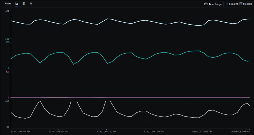
Overall the performance of the VoC sensor data is looking pretty positive, the eCO2 readings need some further investigation as they track the VOC levels. The large spike in the graph below is me putting an open vivid marker on my desk near the sensor.