Random wanderings through Microsoft Azure esp. PaaS plumbing, the IoT bits, AI on Micro controllers, AI on Edge Devices, .NET nanoFramework, .NET Core on *nix and ML.NET+ONNX
namespace devMobile.IoT.myriotaAzureIoTConnector.myriota.UplinkWebhook.Models
{
    public class UplinkPayloadWebDto
    {
        public string EndpointRef { get; set; }
        public long Timestamp { get; set; }
        public string Data { get; set; } // Embedded JSON ?
        public string Id { get; set; }
        public string CertificateUrl { get; set; }
        public string Signature { get; set; }
    }
}
The UplinkWebhook controller “automagically” deserialises the message, then in code the embedded JSON is deserialised and “unpacked”, finally the processed message is inserted into an Azure Storage queue.
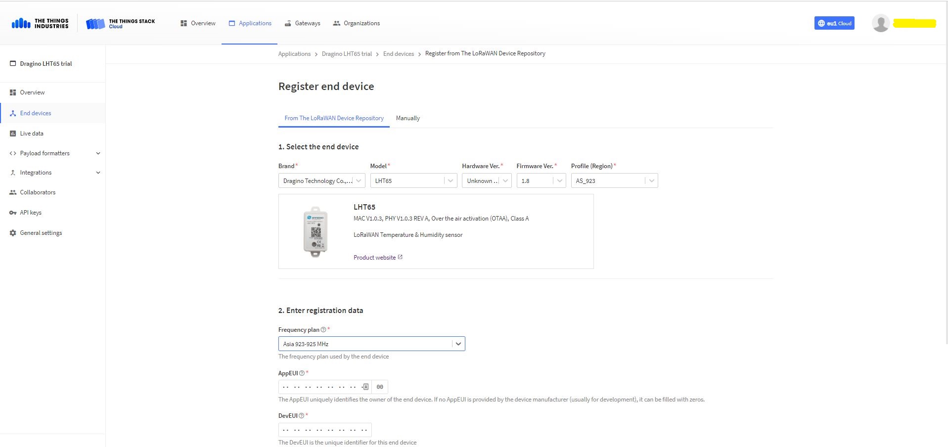
For a couple of weeks Myriota Developer Toolkit has been sitting under my desk and today I got some time to setup a device, register it, then upload some data.
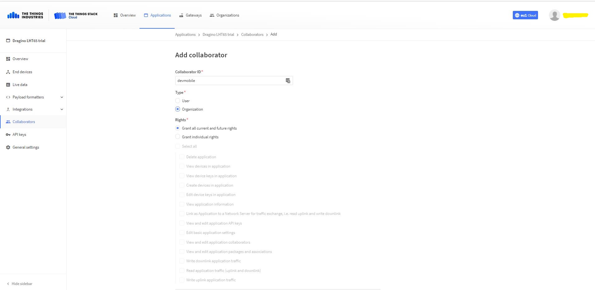
Adding devMobile as a collaborator on the new application
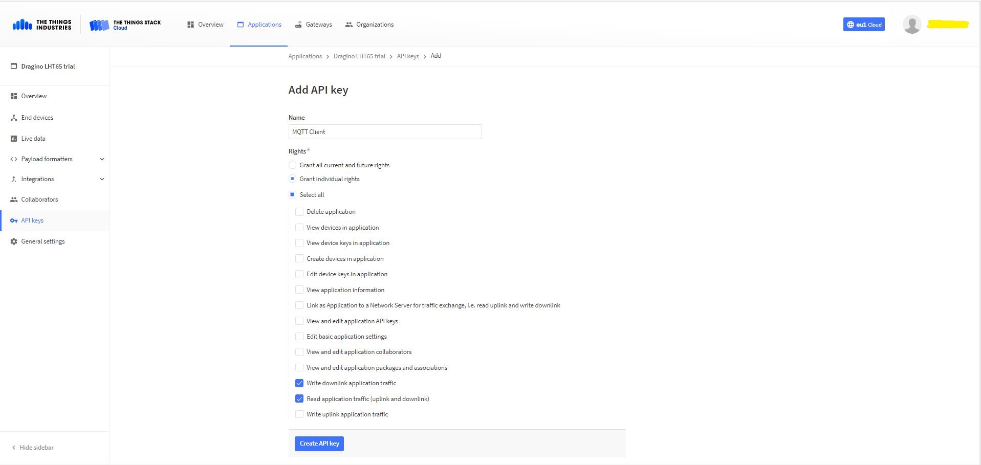
TTI Application API Key configuration
The new Application API Key used by the MQTTnetmanaged client only needs to have write downlink and read uplink traffic enabled.
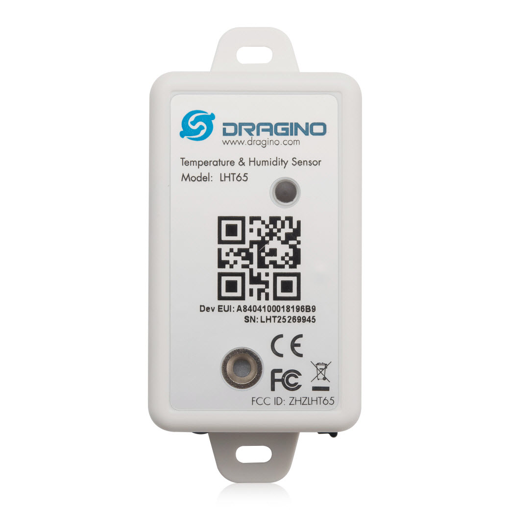
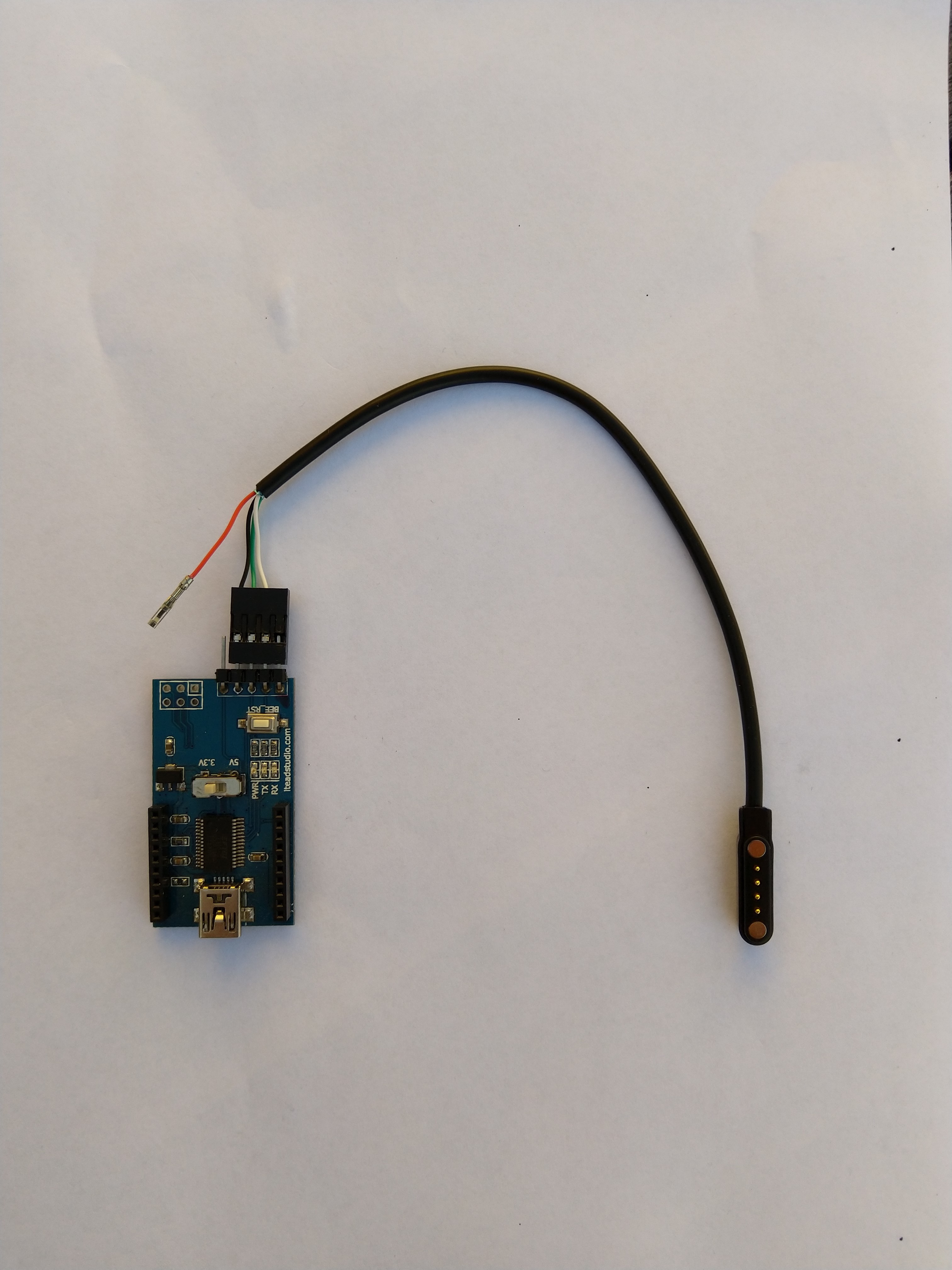
FTDI Adapter and modified LHT64 cable
So I could reliably connect to my LHT65 devices to configure them I modified a programming cable so I could use it with a spare FTDI adaptor without jumper wires. Todo this I used a small jewelers screwdriver to “pop” out the VCC cable and move the transmit data line.
After entering the device password and checking the firmware version I used the AT+CFG command to display the device settings
AT+CFG: Print all configurations

[334428]***** UpLinkCounter= 0 *****
[334430]TX on freq 923200000 Hz at DR 2
[334804]txDone
[339807]RX on freq 923200000 Hz at DR 2
[339868]rxTimeOut
[340807]RX on freq 923200000 Hz at DR 2
[340868]rxTimeOut

Correct Password

Stop Tx events,Please wait for all configurations to print
Printf all config...
AT+DEUI=a8 .. .. .. .. .. .. d6
AT+DADDR=01......D6

AT+APPKEY=9d .. .. .. .. .. .. .. .. .. .. .. .. .. .. 2e
AT+NWKSKEY=f6 .. .. .. .. .. .. .. .. .. .. .. .. .. .. 69
AT+APPSKEY=4c 35 .. .. .. .. .. .. .. .. .. .. .. .. .. 3d
AT+APPEUI=a0 .. .. .. .. .. .. 00
AT+ADR=1
AT+TXP=0
AT+DR=0
AT+DCS=0
AT+PNM=1
AT+RX2FQ=923200000
AT+RX2DR=2
AT+RX1DL=1000
AT+RX2DL=2000
AT+JN1DL=5000
AT+JN2DL=6000
AT+NJM=1
AT+NWKID=00 00 00 00
AT+FCU=0
AT+FCD=0
AT+CLASS=A
AT+NJS=0
AT+RECVB=0:
AT+RECV=0:
AT+VER=v1.7 AS923

AT+CFM=0
AT+CFS=0
AT+SNR=0
AT+RSSI=0
AT+TDC=1200000
AT+PORT=2
AT+PWORD=123456
AT+CHS=0
AT+DATE=21/3/26 07:49:15
AT+SLEEP=0
AT+EXT=4,2
AT+RTP=20
AT+BAT=3120
AT+WMOD=0
AT+ARTEMP=-40,125
AT+CITEMP=1
Start Tx events OK


[399287]***** UpLinkCounter= 0 *****

[399289]TX on freq 923400000 Hz at DR 2

[399663]txDone

[404666]RX on freq 923400000 Hz at DR 2

[404726]rxTimeOut

[405666]RX on freq 923200000 Hz at DR 2

[405726]rxTimeOut
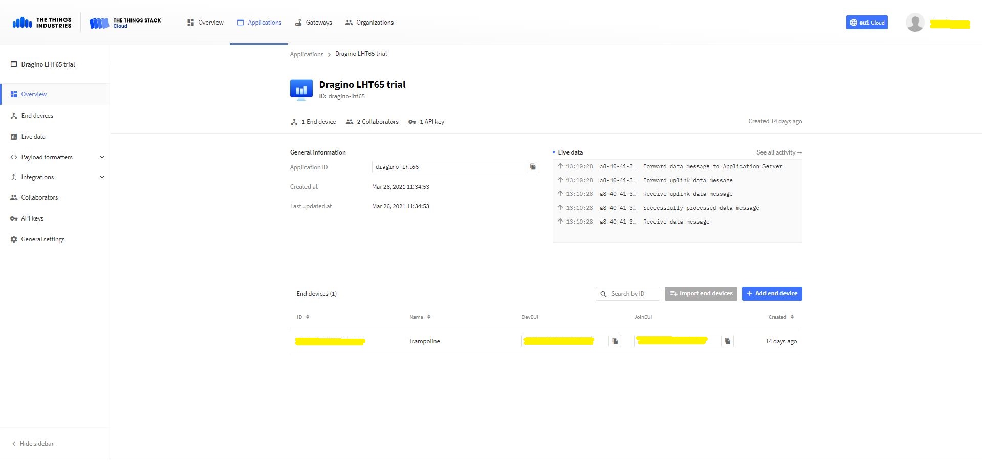
The Dragino LHT65 uses the DeviceEUI as the DeviceID which meant I had todo more redaction in my TTI/TTN and Azure Application Insights screen captures. The rules around the re-use of EndDevice ID were a pain in the arse(PITA) in my development focused tenant.
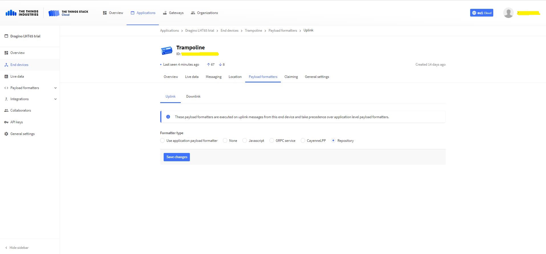
Dragino LHT 65 Device uplink payload formatter
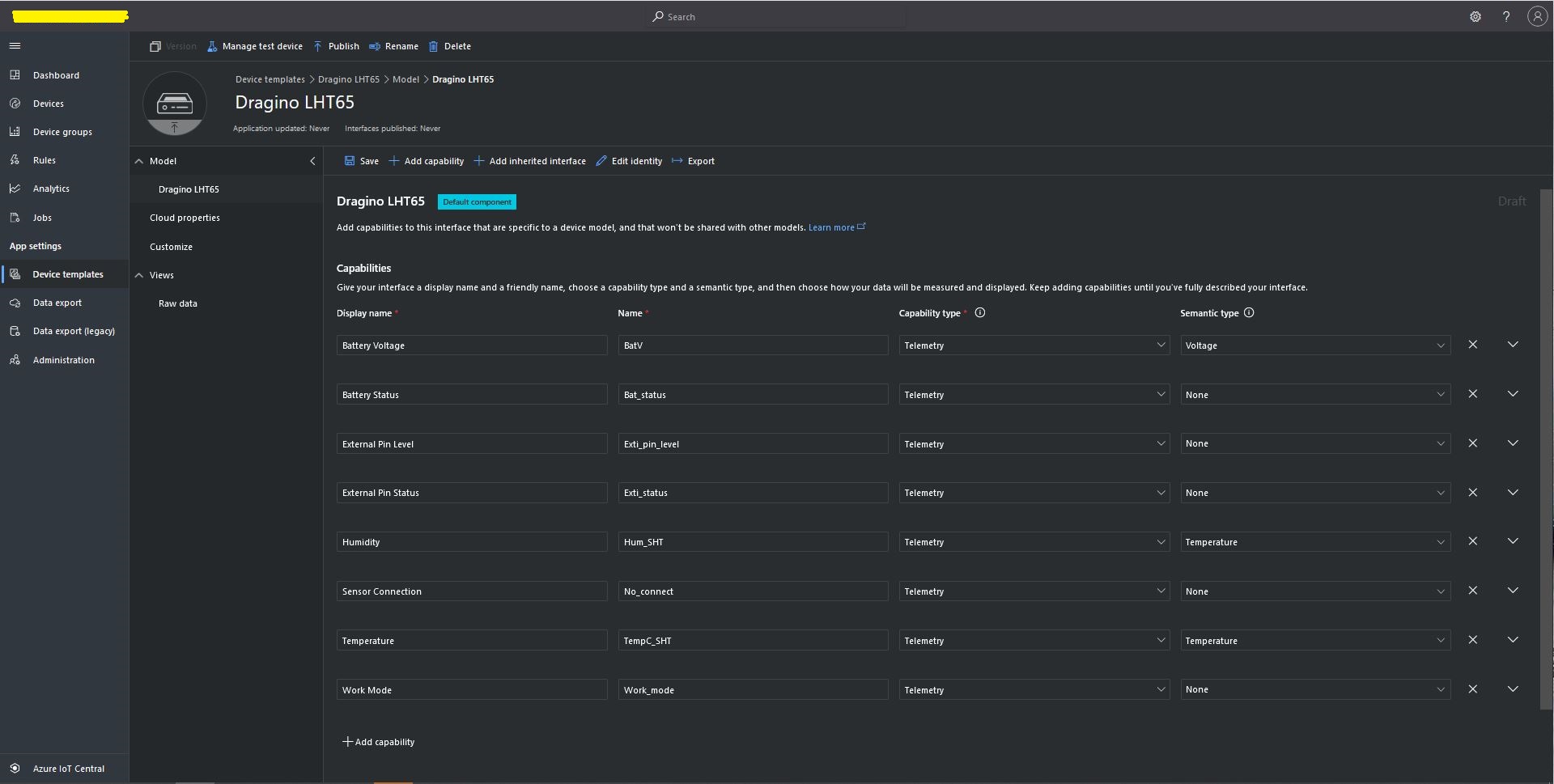
The connector supports both uplink and downlink messages with JSON encoded payloads. The Dragino LHT65 has a vendor supplied formatter which is automatically configured when an EndDevice is created. The EndDevice formatter configuration can also be overridden at the Application level in the app.settings.json file.
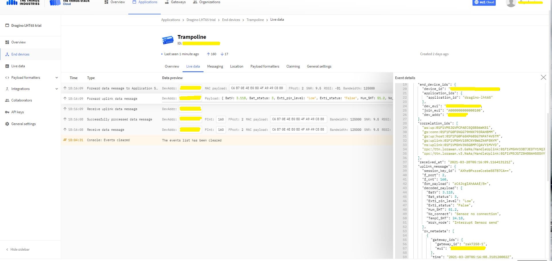
Device Live Data Uplink Data Payload
Once an EndDevice is configured in TTI/TTN I usually use the “Live data Uplink Payload” to work out the decoded payload JSON property names and data types.
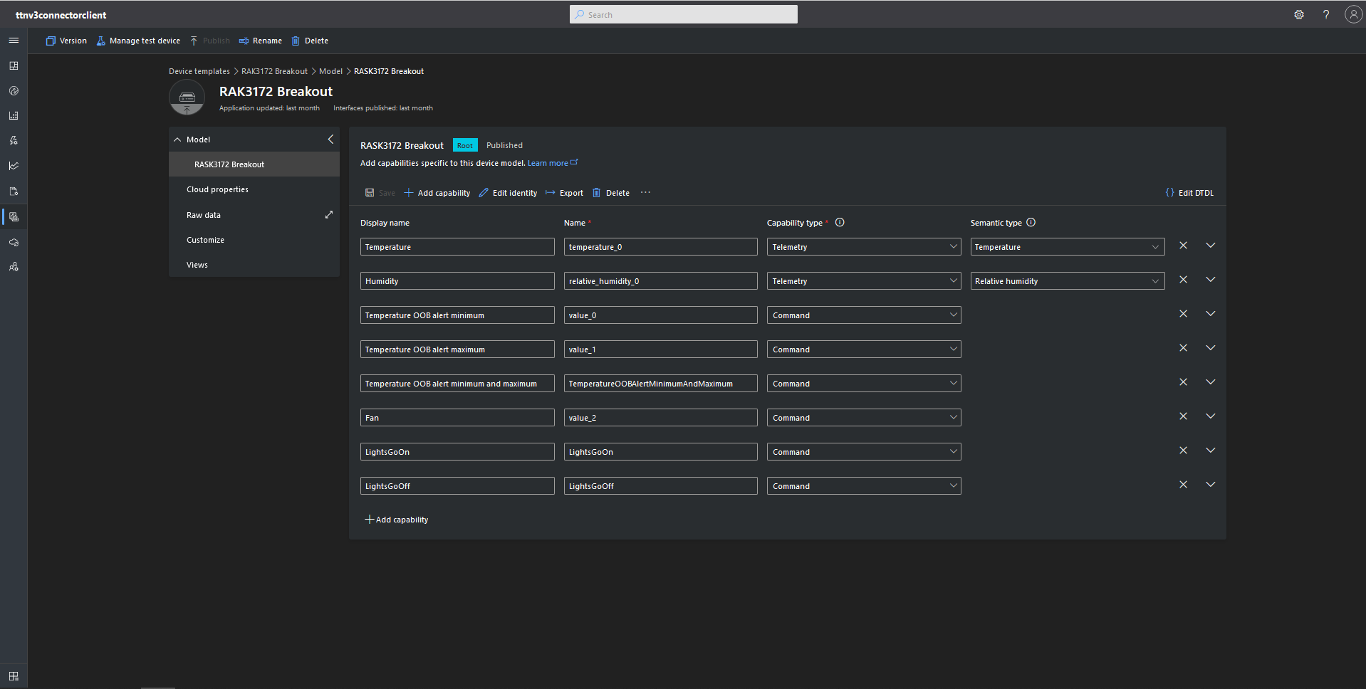
LHT65 Uplink only Azure IoT Central Device Template
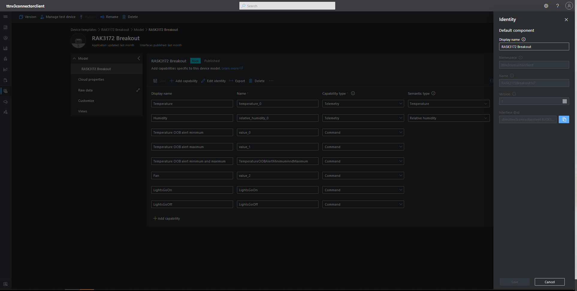
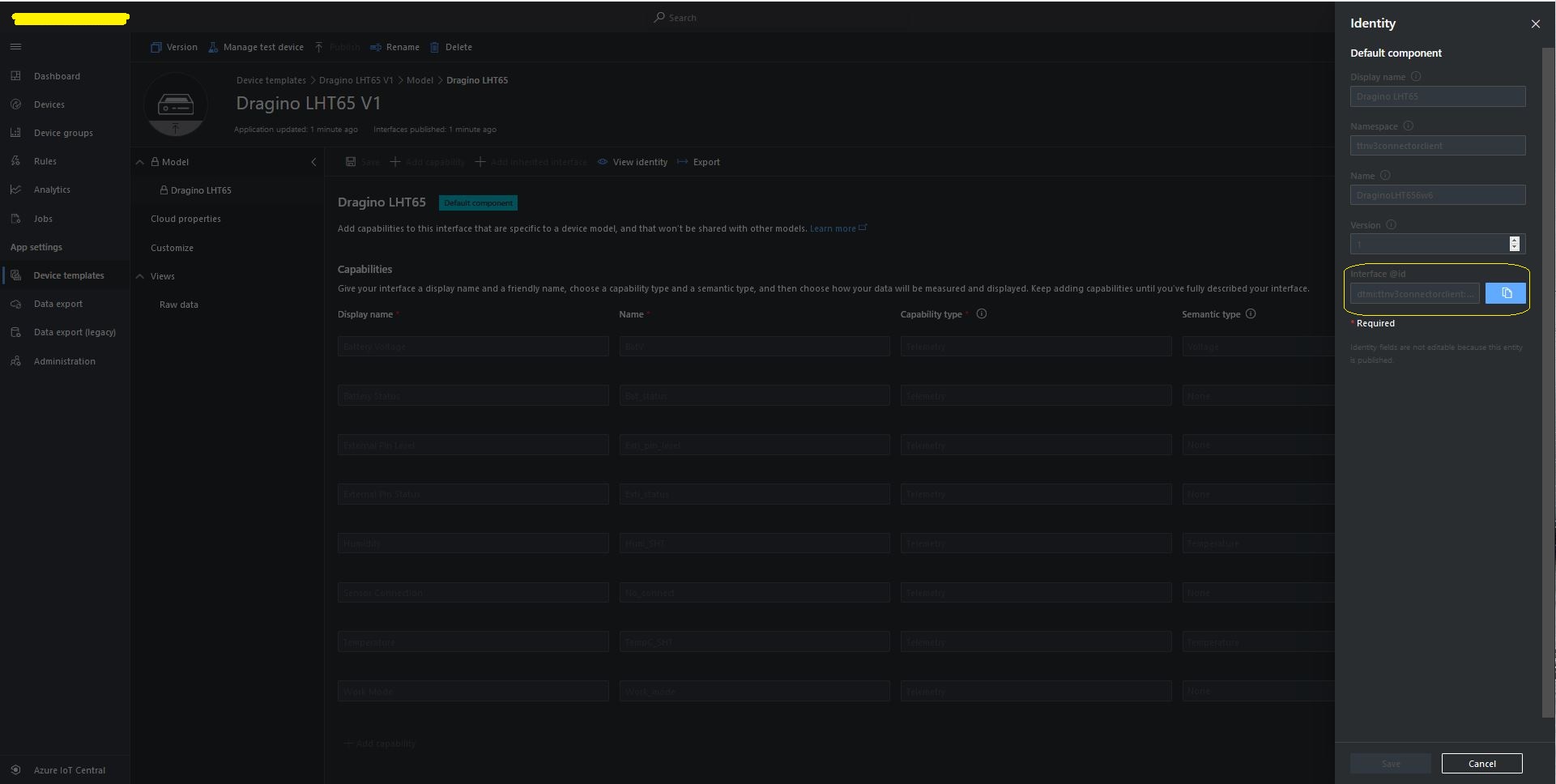
LHT65 Device Template View Identity
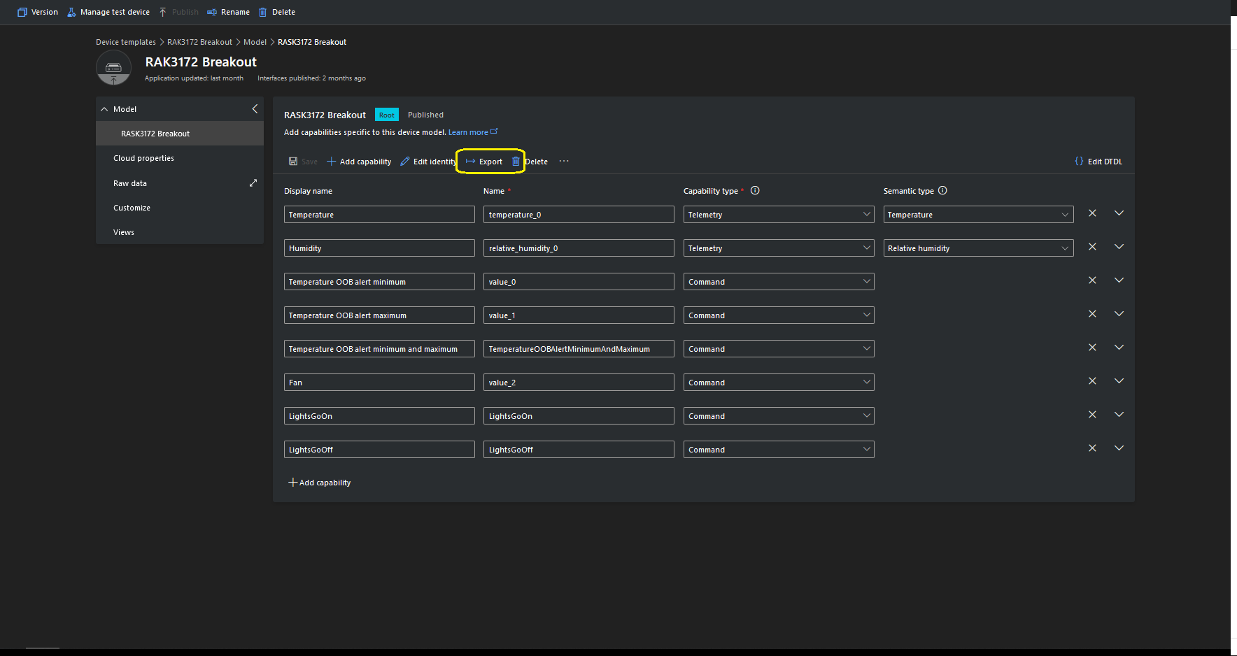
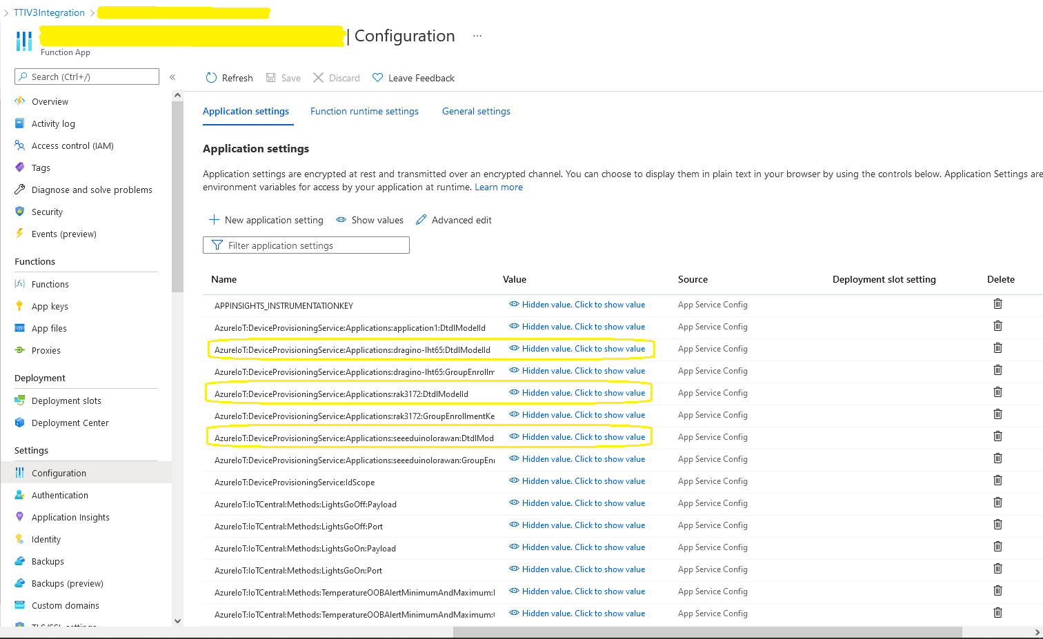
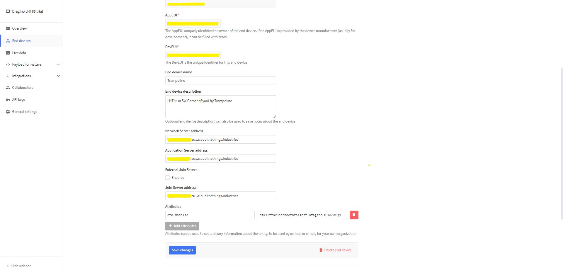
For Azure IoT Central “automagic” provisioning the DTDLModelId has to be copied from the Azure IoT Central Template into the TTI/TTN EndDevice or app.settings.json file application configuration.
LHT65 Device Template copy DTDL @ID
TTI EndDevice configuring the DTDLV2 @ID at the device level
Configuring the DTDLV2 @ID at the TTI application level in the app.settings.json file
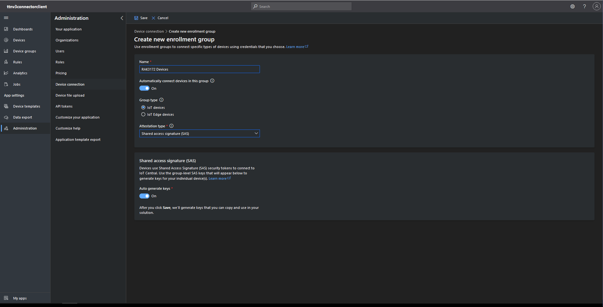
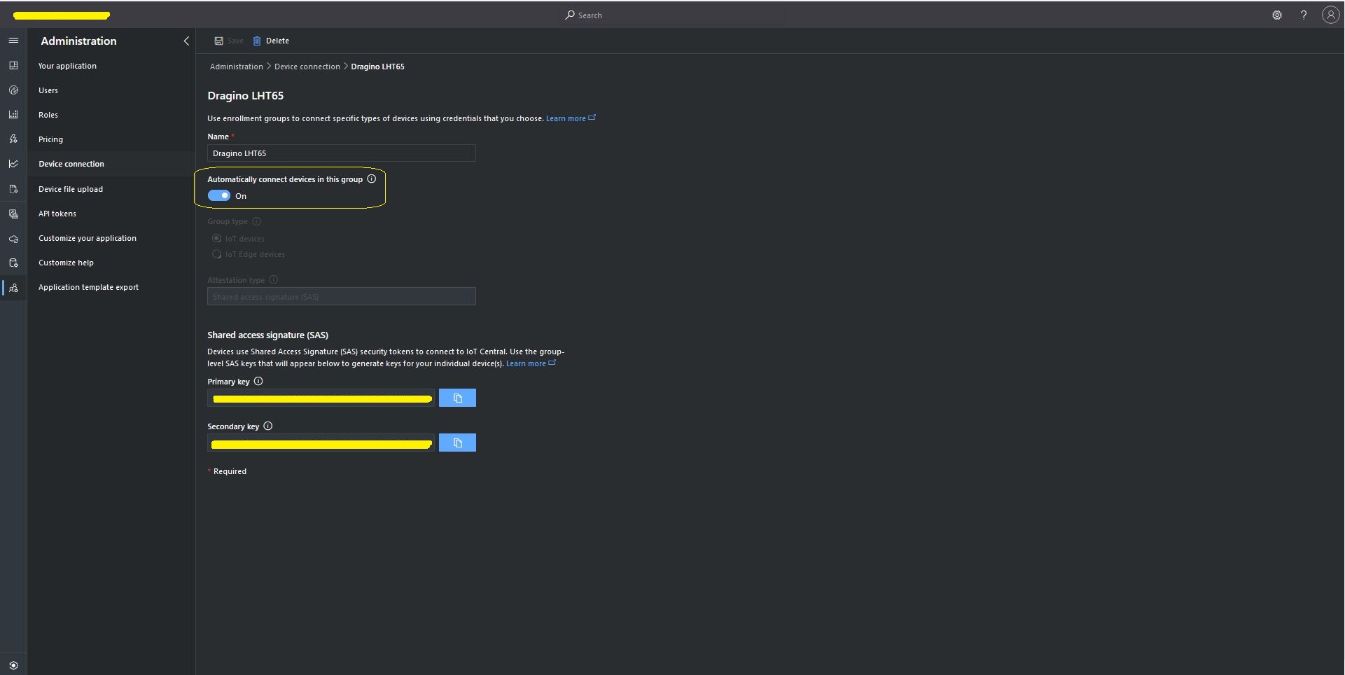
The Azure Device Provisioning Service(DPS) is configured at the TTI application level in the app.settings.json file. The IDScope and one of the Primary or Secondary Shared Access Signature(SAS) keys should be copied into DeviceProvisioningServiceSettings of an Application in the app.settings.json file. I usually set the “Automatically connect devices in this group” flag as part of the “automagic” provisioning process.
Azure IoT Central Group Enrollment Key
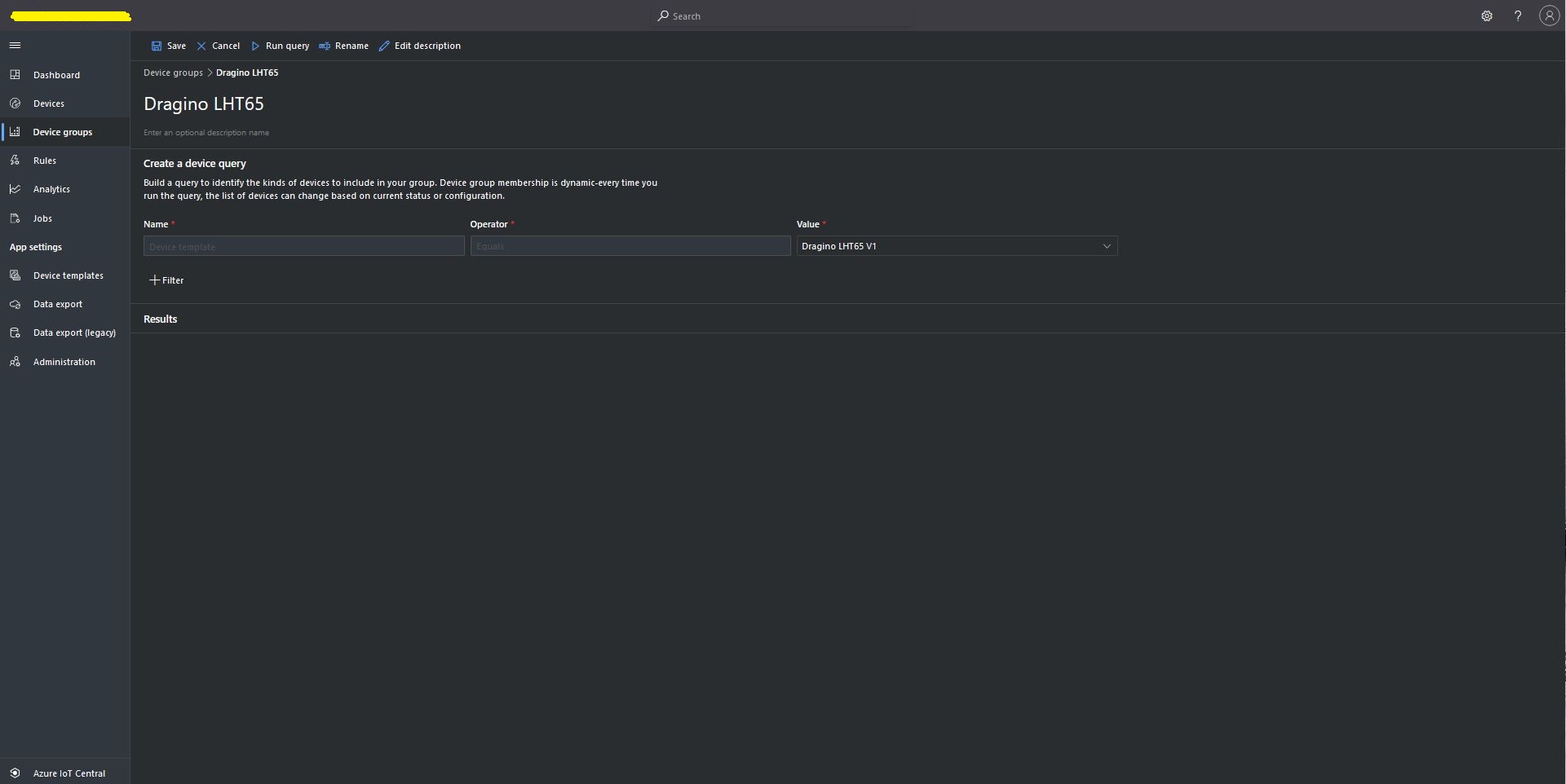
Then device templates need to be mapped to an Enrollment Group then Device Group.
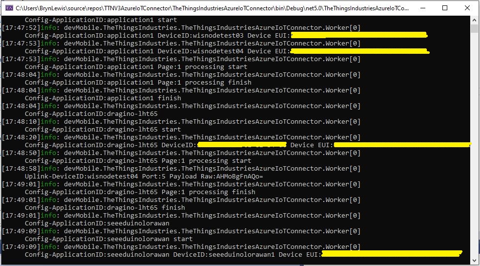
For testing the connector application can be run locally with diagnostic information displayed in the application console window as it “automagically’ provisions devices and uploads telemetry data.
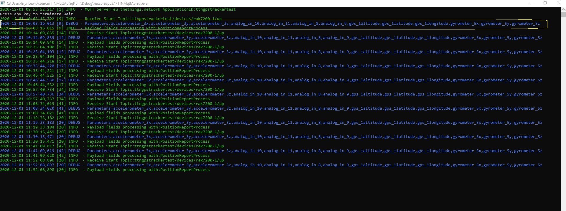
Connector application Diagnostics
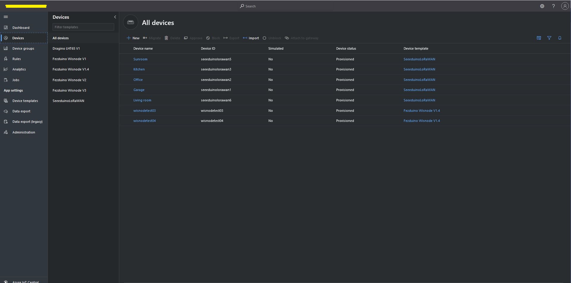
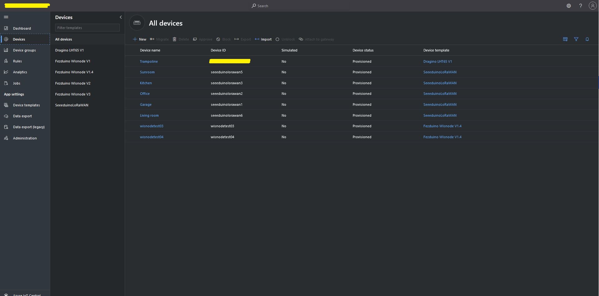
Azure IoT Central Device list before my LHT65 device is “automagically” provisioned
Azure IoT Central Device list after my LHT65 device is “automagically” provisioned
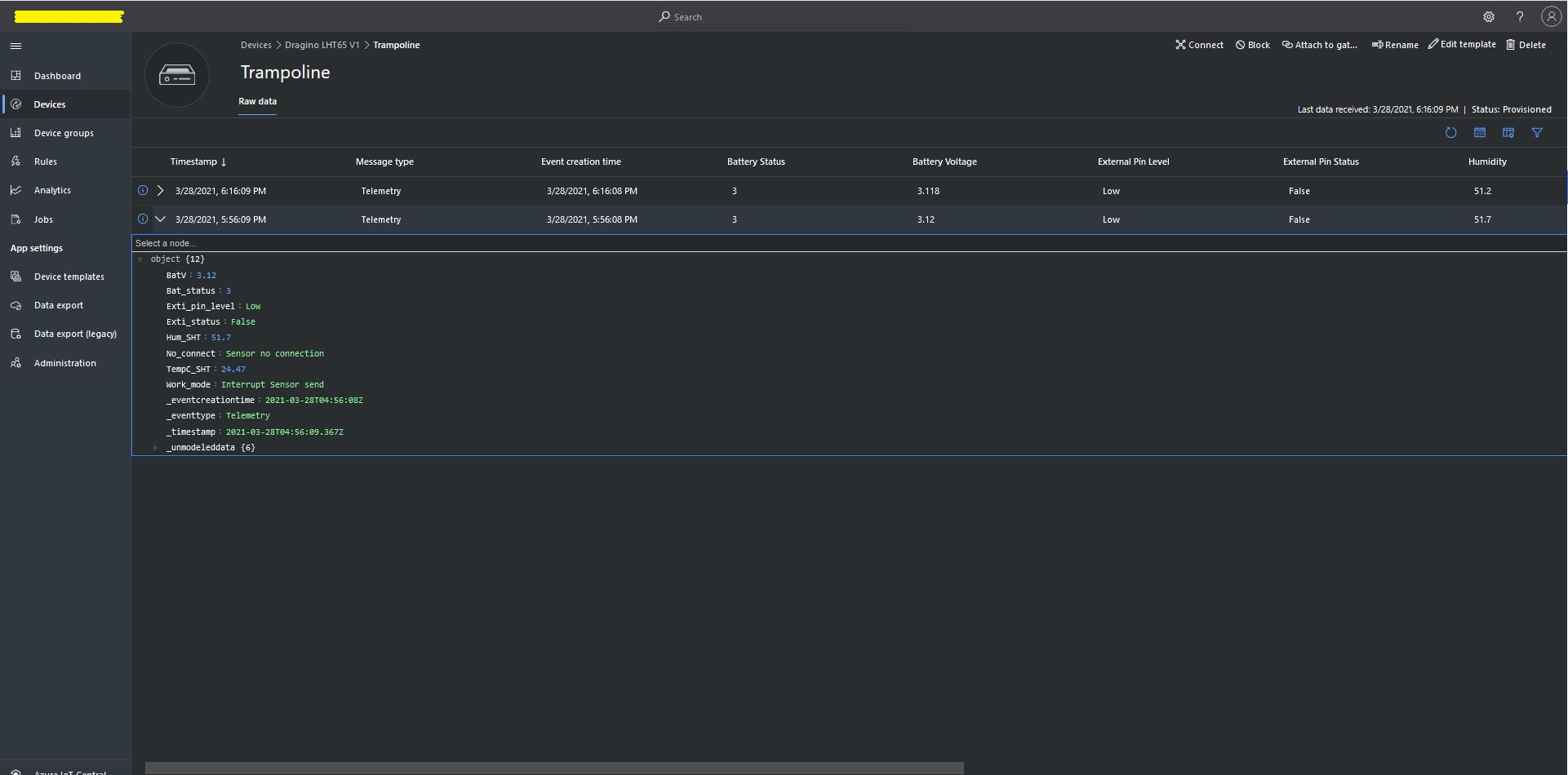
One a device has been provisioned I check on the raw data display that all the fields I configured have been mapped correctly.
Azure IoT Central raw data display
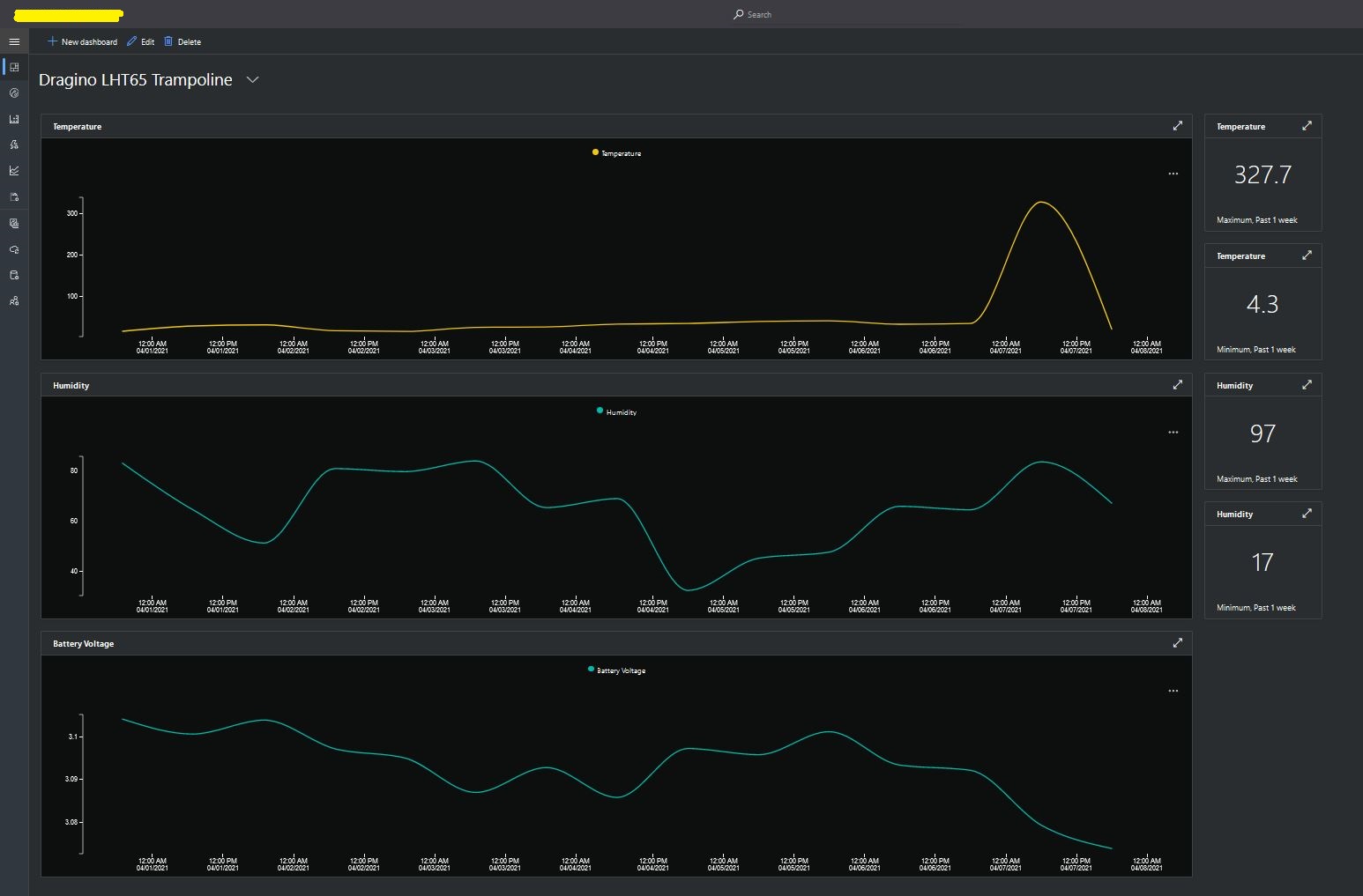
I then created a dashboard to display the telemetry data from the LHT65 sensors.
Azure IoT Central dashboard displaying LHT65 temperature, humidity and battery voltage graphs.
The dashboard also has a few KPI displays which highlighted an issue which occurs a couple of times a month with the LHT65 onboard temperature sensor values (327.7°). I have connected Dragino technical support and have also been unable to find a way to remove the current an/or filter out future aberrant values.
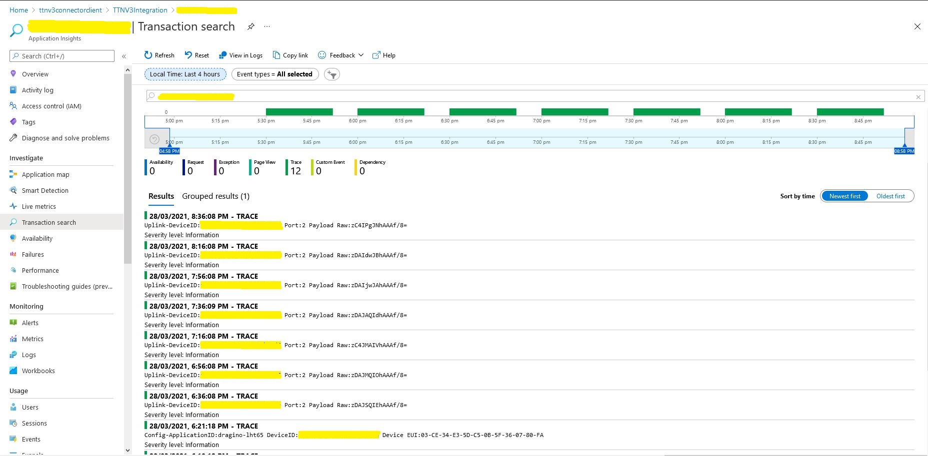
Azure Application Insights logging
I also noticed that the formatting of the DeviceEUI values in the Application Insights logging was incorrect after trying to search for one of my Seeedstudio LoRaWAN device with its DeviceEUI.
This code was written to solve a problem I had debugging and testing an application which processed data from sensors attached to The Things Network(TTN) and I figured others might find it useful.
As part of my series of TTN projects I wanted to verify that the data from a number of LoRaWAN sensors connected to TTN was reasonable and complete. I’m familiar with Microsoft SQL Server so I built a .Net Core console application which uses the TTN Message Queue Telemetry Transport(MQTT) Data API (so it can run alongside my existing TTN integration) to receive messages from the all devices in a TTN application and store them in a database for post processing.
The console application uses MQTTNet to connect to TTN MQTT Data API. It subscribes to an application device uplink topic, then uses a combination of Stackoverflow Dapper with Microsoft SQL Server tables and stored procedures to store the device data points. I re-generated the classes I had used in my other projects, added any obvious missing fields and fine tuned the data types by delving into the TTN V2GO code.
The core of the application is in the MQTTNet application message received handler.
private static void MqttClient_ApplicationMessageReceived(MqttApplicationMessageReceivedEventArgs e)
{
   PayloadUplinkV2 payload;

   log.InfoFormat($"Receive Start Topic:{e.ApplicationMessage.Topic}");

   string connectionString = configuration.GetSection("TTNDatabase").Value;

   try
   {
      payload = JsonConvert.DeserializeObject<PayloadUplinkV2>(e.ApplicationMessage.ConvertPayloadToString());
   }
   catch (Exception ex)
   {
      log.Error("DeserializeObject failed", ex);
      return;
   }

   try
   {
      if (payload.PayloadFields != null)
      {
         var parameters = new DynamicParameters();

         EnumerateChildren(parameters, payload.PayloadFields);

         log.Debug($"Parameters:{parameters.ParameterNames.Aggregate((i, j) => i + ',' + j)}");

         foreach (string storedProcedure in storedProcedureMappings.Keys)
         {
            if (Enumerable.SequenceEqual(parameters.ParameterNames, storedProcedureMappings[storedProcedure].Split(',', StringSplitOptions.RemoveEmptyEntries), StringComparer.InvariantCultureIgnoreCase))
            {
               log.Info($"Payload fields processing with:{storedProcedure}");

               using (SqlConnection db = new SqlConnection(connectionString))
               {
                  parameters.Add("@ReceivedAtUtc", payload.Metadata.ReceivedAtUtc);
                  parameters.Add("@DeviceID", payload.DeviceId);
                  parameters.Add("@DeviceEui", payload.DeviceEui);
                  parameters.Add("@ApplicationID", payload.ApplicationId);
                  parameters.Add("@IsConfirmed", payload.IsConfirmed);
                  parameters.Add("@IsRetry", payload.IsRetry);
                  parameters.Add("@Port", payload.Port);

                  db.Execute(sql: storedProcedure, param: parameters, commandType: CommandType.StoredProcedure);
               }
            }
         }
      }
      else
      {
         foreach (string storedProcedure in storedProcedureMappings.Keys)
         {
            if (string.Compare(storedProcedureMappings[storedProcedure], "payload_raw", true) == 0)
            {
               log.Info($"Payload raw processing with:{storedProcedure}");

               using (SqlConnection db = new SqlConnection(connectionString))
               {
                  var parameters = new DynamicParameters();

                  parameters.Add("@ReceivedAtUtc", payload.Metadata.ReceivedAtUtc);
                  parameters.Add("@DeviceID", payload.DeviceId);
                  parameters.Add("@DeviceEui", payload.DeviceEui);
                  parameters.Add("@ApplicationID", payload.ApplicationId);
                  parameters.Add("@IsConfirmed", payload.IsConfirmed);
                  parameters.Add("@IsRetry", payload.IsRetry);
                  parameters.Add("@Port", payload.Port);
                  parameters.Add("@Payload", payload.PayloadRaw);

                  db.Execute(sql: storedProcedure, param: parameters, commandType: CommandType.StoredProcedure);
               }
            }
         }
      }
   }
   catch (Exception ex)
   {
      log.Error("Message processing failed", ex);
   }
}
For messages with payload fields the code attempts to match the list of field names (there maybe more than one match) with the parameter list for stored procedures in the AppSettings.json file. The Enumerable.SequenceEqual uses a case insensitive comparison but order is important. I did consider sorting the two lists of parameters but wasn’t certain the added complexity was worth it.
I created a database table to store the temperature and humidity values.
CREATE TABLE [dbo].[EnvironmentalSensorReport](
	[WeatherSensorReportUID] [UNIQUEIDENTIFIER] NOT NULL,
	[ReceivedAtUtC] [DATETIME] NOT NULL,
	[DeviceID] [NVARCHAR](32) NOT NULL,
	[DeviceEui] [NVARCHAR](32) NOT NULL,
	[ApplicationID] [NVARCHAR](32) NOT NULL,
	[IsConfirmed] [BIT] NOT NULL,
	[IsRetry] [BIT] NOT NULL,
	[Port] [SMALLINT] NOT NULL,
	[Temperature] [FLOAT] NOT NULL,
	[Humidity] [FLOAT] NOT NULL,
CONSTRAINT [PK_EnvironmentalSensorReport] PRIMARY KEY CLUSTERED
(
	[WeatherSensorReportUID] ASC
)WITH (PAD_INDEX = OFF, STATISTICS_NORECOMPUTE = OFF, IGNORE_DUP_KEY = OFF, ALLOW_ROW_LOCKS = ON, ALLOW_PAGE_LOCKS = ON) ON [PRIMARY]
) ON [PRIMARY]
GO

ALTER TABLE [dbo].[EnvironmentalSensorReport] ADD  CONSTRAINT [DF_EnvironmentalSensorReport_EnvironmentalSensorReporttUID]  DEFAULT (NEWID()) FOR [WeatherSensorReportUID]
GO
The stored procedure must have the parameters @ReceivedAtUtc, @DeviceID, @DeviceEui, @ApplicationID, @IsRetry, @IsConfirmed and @Port. In this example the payload specific fields generated by the Low Power Protocol(LPP) decoder are @Temperature_0 and @relative_humidity_0
CREATE PROCEDURE [dbo].[EnvironmentalSensorProcess]
   @ReceivedAtUtc AS DATETIME,
   @DeviceID AS NVARCHAR(32),
   @DeviceEui AS NVARCHAR(32),
   @ApplicationID AS NVARCHAR(32),
   @IsRetry AS BIT,
   @IsConfirmed AS BIT,
   @Port AS SMALLINT,
   @Temperature_0 AS FLOAT,
   @relative_humidity_0 AS FLOAT
AS
BEGIN
   SET NOCOUNT ON;

   INSERT INTO [dbo].[EnvironmentalSensorReport]
           ([PositionReportUID]
	   .[ReceivedAtUtc]
           ,[DeviceID]
           ,[DeviceEui]
           ,[ApplicationID]
           ,[IsConfirmed]
           ,[IsRetry]
           ,[Port]
	   ,Temperature
	   ,Humidity)
   VALUES
   (
      @ReceivedAtUtc,
      @DeviceID,
      @DeviceEui,
      @ApplicationID,
      @IsConfirmed,
      @IsRetry,
      @port,
      @Temperature_0,
      @relative_humidity_0)
END
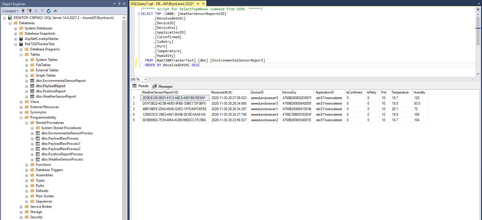
Environmental sensor data displayed in SQL Server Management Studio(SSMS)
To store more complex nest payload fields (e.g. latitude, longitude and altitude values), I flattened the the hierarchy.
private static void EnumerateChildren(DynamicParameters parameters, JToken token, string prefix ="")
{
   if (token is JProperty)
      if (token.First is JValue)
      {
         JProperty property = (JProperty)token;
         parameters.Add($"@{prefix}{property.Name}", property.Value.ToString());
      }
      else
      {
         JProperty property = (JProperty)token;
         prefix += property.Name;
      }

   foreach (JToken token2 in token.Children())
   {
      EnumerateChildren(parameters,token2, prefix);
   }
}
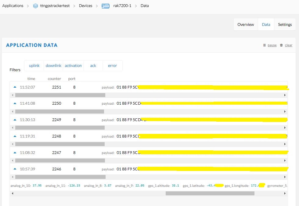
Unpacked LPP payload from GPS tracker displayed in TTN application data viewFlattened location, acceleration and rotation information
CREATE TABLE [dbo].[PositionReport](
      [PositionReportUID] [UNIQUEIDENTIFIER] NOT NULL,
      [ReceivedAtUtC] [DATETIME] NOT NULL,
      [DeviceID] [NVARCHAR](32) NOT NULL,
      [DeviceEui] [NVARCHAR](32) NOT NULL,
      [ApplicationID] [NVARCHAR](32) NOT NULL,
      [IsConfirmed] [BIT] NOT NULL,
      [IsRetry] [BIT] NOT NULL,
      [Port] [SMALLINT] NOT NULL,
      [Latitude] [FLOAT] NOT NULL,
      [Longitude] [FLOAT] NOT NULL,
      [Altitude] [FLOAT] NOT NULL,
 CONSTRAINT [PK_PositionReport] PRIMARY KEY CLUSTERED
(
	[PositionReportUID] ASC
)WITH (PAD_INDEX = OFF, STATISTICS_NORECOMPUTE = OFF, IGNORE_DUP_KEY = OFF, ALLOW_ROW_LOCKS = ON, ALLOW_PAGE_LOCKS = ON) ON [PRIMARY]
) ON [PRIMARY]
GO
I created a database table to store values of only the fields I cared about.
CREATE PROCEDURE [dbo].[PositionReportProcess]
      @ReceivedAtUtc AS DATETIME,
      @DeviceID AS NVARCHAR(32),
      @DeviceEui AS NVARCHAR(32),
      @ApplicationID AS NVARCHAR(32),
      @IsRetry AS Bit,
      @IsConfirmed AS BIT,
      @Port AS SMALLINT,
      @accelerometer_3x AS FLOAT,
      @accelerometer_3y AS FLOAT,
      @accelerometer_3z AS FLOAT,
      @analog_in_8 AS FLOAT,
      @analog_in_9 AS FLOAT,
      @analog_in_10 AS FLOAT,
      @analog_in_11 AS FLOAT,
      @gps_1Latitude AS FLOAT,
      @gps_1Longitude AS FLOAT,
      @gps_1Altitude AS FLOAT,
      @gyrometer_5x  AS FLOAT,
      @gyrometer_5y  AS FLOAT,
      @gyrometer_5z  AS FLOAT
AS
BEGIN
   SET NOCOUNT ON;

   INSERT INTO [dbo].[PositionReport]
      ([PositionReportUID]
      .[ReceivedAtUtc]
      ,[DeviceID]
      ,[DeviceEui]
      ,[ApplicationID]
      ,[IsConfirmed]
      ,[IsRetry]
      ,[Port]
      ,Latitude
      ,Longitude
      ,Altitude)
   VALUES
   (
      @ReceivedAtUtc,
      @DeviceID,
      @DeviceEui,
      @ApplicationID,
      @IsConfirmed,
      @IsRetry,
      @port,
      @gps_1Latitude,
      @gps_1Longitude,
      @gps_1Altitude)
END
The stored procedure for storing the GPS tracker payload has to have parameters matching each payload field but some of the fields are not used.
Location data displayed in SQL Server Management Studio(SSMS)
For uplink messages with no payload fields the message processor looks for a stored procedure with a single parameter called “payload_raw”.(there maybe more than one match)
CREATE TABLE [dbo].[PayloadReport](
      [PayloadReportUID] [UNIQUEIDENTIFIER] NOT NULL,
      [ReceivedAtUtC] [DATETIME] NOT NULL,
      [DeviceID] [NVARCHAR](32) NOT NULL,
      [DeviceEui] [NVARCHAR](32) NOT NULL,
      [ApplicationID] [NVARCHAR](32) NOT NULL,
      [IsConfirmed] [BIT] NOT NULL,
      [IsRetry] [BIT] NOT NULL,
      [Port] [SMALLINT] NOT NULL,
      [Payload] [NVARCHAR](128) NOT NULL,
CONSTRAINT [PK_PayloadReport] PRIMARY KEY CLUSTERED
(
      [PayloadReportUID] ASC
)WITH (PAD_INDEX = OFF, STATISTICS_NORECOMPUTE = OFF, IGNORE_DUP_KEY = OFF, ALLOW_ROW_LOCKS = ON, ALLOW_PAGE_LOCKS = ON) ON [PRIMARY]
) ON [PRIMARY]
GO

ALTER TABLE [dbo].[PayloadReport] ADD  CONSTRAINT [DF_PayloadReport_PositionReportUID]  DEFAULT (NEWID()) FOR [PayloadReportUID]
GO
ALTER PROCEDURE [dbo].[PayloadRawProcess]
      @ReceivedAtUtc AS DATETIME,
      @DeviceID AS NVARCHAR(32),
      @DeviceEui AS NVARCHAR(32),
      @ApplicationID AS NVARCHAR(32),
      @IsRetry AS Bit,
      @IsConfirmed AS BIT,
      @Port AS SMALLINT,
      @Payload AS NVARCHAR(128)
AS
BEGIN
      SET NOCOUNT ON;

      INSERT INTO [dbo].[PayloadReport]
         ([PositionReportUID]
         .[ReceivedAtUtc]
         ,[DeviceID]
         ,[DeviceEui]
         ,[ApplicationID]
         ,[IsConfirmed]
         ,[IsRetry]
         ,[Port]
         ,[Payload])
     VALUES(@ReceivedAtUtc,
         @DeviceID,
         @DeviceEui,
         @ApplicationID,
         @IsConfirmed,
         @IsRetry,
         @port,
         @Payload)
END
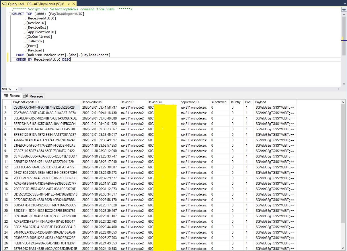
Raw payload data displayed in SQL Server Management Studio(SSMS)
Initially the application just used Console.Writeline for logging, then I added Log4Net because it would be useful to persist information about failures and so I could copy n paste parameter lists to the appSettings.json file.
The first step was to confirm the transmission of messages with polled completion confirmation was working as expected.
class Program
{
static void Main()
{
#if TINYCLR_V2_SC20100DEV
Rfm9XDevice rfm9XDevice = new Rfm9XDevice(SC20100.SpiBus.Spi3, SC20100.GpioPin.PA13, SC20100.GpioPin.PA14);
#endif
#if TINYCLR_V2_FEZDUINO
Rfm9XDevice rfm9XDevice = new Rfm9XDevice(SC20100.SpiBus.Spi6, SC20100.GpioPin.PB1, SC20100.GpioPin.PA15);
#endif
int SendCount = 0;
// Put device into LoRa + Sleep mode
rfm9XDevice.RegisterWriteByte(0x01, 0b10000000); // RegOpMode
// Set the frequency to 915MHz
byte[] frequencyWriteBytes = { 0xE4, 0xC0, 0x00 }; // RegFrMsb, RegFrMid, RegFrLsb
rfm9XDevice.RegisterWrite(0x06, frequencyWriteBytes);
// More power PA Boost
rfm9XDevice.RegisterWriteByte(0x09, 0b10000000); // RegPaConfig
rfm9XDevice.RegisterDump();
while (true)
{
rfm9XDevice.RegisterWriteByte(0x0E, 0x0); // RegFifoTxBaseAddress
// Set the Register Fifo address pointer
rfm9XDevice.RegisterWriteByte(0x0D, 0x0); // RegFifoAddrPtr
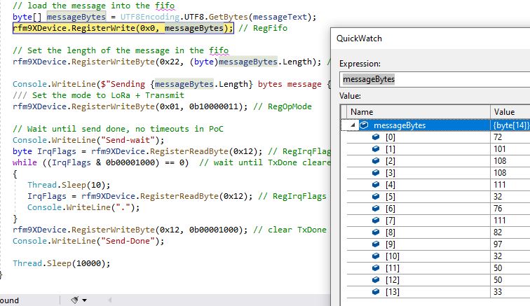
string messageText = $"Hello LoRa {SendCount += 1}!";
// load the message into the fifo
byte[] messageBytes = UTF8Encoding.UTF8.GetBytes(messageText);
rfm9XDevice.RegisterWrite(0x0, messageBytes); // RegFifo
// Set the length of the message in the fifo
rfm9XDevice.RegisterWriteByte(0x22, (byte)messageBytes.Length); // RegPayloadLength
Debug.WriteLine($"Sending {messageBytes.Length} bytes message {messageText}");
/// Set the mode to LoRa + Transmit
rfm9XDevice.RegisterWriteByte(0x01, 0b10000011); // RegOpMode
// Wait until send done, no timeouts in PoC
Debug.WriteLine("Send-wait");
byte IrqFlags = rfm9XDevice.RegisterReadByte(0x12); // RegIrqFlags
while ((IrqFlags & 0b00001000) == 0) // wait until TxDone cleared
{
Thread.Sleep(10);
IrqFlags = rfm9XDevice.RegisterReadByte(0x12); // RegIrqFlags
Debug.WriteLine(".");
}
rfm9XDevice.RegisterWriteByte(0x12, 0b00001000); // clear TxDone bit
Debug.WriteLine("Send-Done");
Thread.Sleep(30000);
}
}
}
The diagnostic output shows messages being sent and on another device I could see the messages arriving. I do wonder why the first message often takes so long to send?
Register dump
Register 0x00 - Value 0Xc3
Register 0x01 - Value 0X80
Register 0x02 - Value 0X1a
Register 0x03 - Value 0X0b
Register 0x04 - Value 0X00
Register 0x05 - Value 0X52
Register 0x06 - Value 0Xe4
Register 0x07 - Value 0Xc0
Register 0x08 - Value 0X00
Register 0x09 - Value 0X80
Register 0x0a - Value 0X09
Register 0x0b - Value 0X2b
Register 0x0c - Value 0X20
Register 0x0d - Value 0X01
Register 0x0e - Value 0X80
Register 0x0f - Value 0X00
Register 0x10 - Value 0X00
Register 0x11 - Value 0X00
Register 0x12 - Value 0X00
Register 0x13 - Value 0X00
Register 0x14 - Value 0X00
Register 0x15 - Value 0X00
Register 0x16 - Value 0X00
Register 0x17 - Value 0X00
Register 0x18 - Value 0X10
Register 0x19 - Value 0X00
Register 0x1a - Value 0X00
Register 0x1b - Value 0X00
Register 0x1c - Value 0X00
Register 0x1d - Value 0X72
Register 0x1e - Value 0X70
Register 0x1f - Value 0X64
Register 0x20 - Value 0X00
Register 0x21 - Value 0X08
Register 0x22 - Value 0X01
Register 0x23 - Value 0Xff
Register 0x24 - Value 0X00
Register 0x25 - Value 0X00
Register 0x26 - Value 0X04
Register 0x27 - Value 0X00
Register 0x28 - Value 0X00
Register 0x29 - Value 0X00
Register 0x2a - Value 0X00
Register 0x2b - Value 0X00
Register 0x2c - Value 0X00
Register 0x2d - Value 0X50
Register 0x2e - Value 0X14
Register 0x2f - Value 0X45
Register 0x30 - Value 0X55
Register 0x31 - Value 0Xc3
Register 0x32 - Value 0X05
Register 0x33 - Value 0X27
Register 0x34 - Value 0X1c
Register 0x35 - Value 0X0a
Register 0x36 - Value 0X03
Register 0x37 - Value 0X0a
Register 0x38 - Value 0X42
Register 0x39 - Value 0X12
Register 0x3a - Value 0X49
Register 0x3b - Value 0X1d
Register 0x3c - Value 0X00
Register 0x3d - Value 0Xaf
Register 0x3e - Value 0X00
Register 0x3f - Value 0X00
Register 0x40 - Value 0X00
Register 0x41 - Value 0X00
Register 0x42 - Value 0X12
Sending 13 bytes message Hello LoRa 1!
Send-wait
.
.
.
.
.
Send-Done
Sending 13 bytes message Hello LoRa 2!
Send-wait
Send-Done
Sending 13 bytes message Hello LoRa 3!
Send-wait
Send-Done
Sending 13 bytes message Hello LoRa 4!
Send-wait
Send-Done
Sending 13 bytes message Hello LoRa 5!
Send-wait
Send-Done
Sending 13 bytes message Hello LoRa 6!
Send-wait
Send-Done
The second step was to confirm the polled reception of messages was working as expected.
   class Program
   {
      static void Main()
      {
#if TINYCLR_V2_SC20100DEV
         Rfm9XDevice rfm9XDevice = new Rfm9XDevice(SC20100.SpiBus.Spi3, SC20100.GpioPin.PA13, SC20100.GpioPin.PA14);
#endif
#if TINYCLR_V2_FEZDUINO
         Rfm9XDevice rfm9XDevice = new Rfm9XDevice(SC20100.SpiBus.Spi6, SC20100.GpioPin.PB1, SC20100.GpioPin.PA15);
#endif


         // Put device into LoRa + Sleep mode
         rfm9XDevice.RegisterWriteByte(0x01, 0b10000000); // RegOpMode

         // Set the frequency to 915MHz
         byte[] frequencyWriteBytes = { 0xE4, 0xC0, 0x00 }; // RegFrMsb, RegFrMid, RegFrLsb
         rfm9XDevice.RegisterWrite(0x06, frequencyWriteBytes);

         rfm9XDevice.RegisterWriteByte(0x0F, 0x0); // RegFifoRxBaseAddress

         rfm9XDevice.RegisterWriteByte(0x01, 0b10000101); // RegOpMode set LoRa & RxContinuous

         while (true)
         {
            // Wait until a packet is received, no timeouts in PoC
            Debug.WriteLine("Receive-Wait");
            byte irqFlags = rfm9XDevice.RegisterReadByte(0x12); // RegIrqFlags
            while ((irqFlags & 0b01000000) == 0)  // wait until RxDone cleared
            {
               Thread.Sleep(100);
               irqFlags = rfm9XDevice.RegisterReadByte(0x12); // RegIrqFlags
               //Debug.Write(".");
            }
            Debug.WriteLine("");
            Debug.WriteLine($"RegIrqFlags 0X{irqFlags:X2}");
            Debug.WriteLine("Receive-Message");
            byte currentFifoAddress = rfm9XDevice.RegisterReadByte(0x10); // RegFifiRxCurrent
            rfm9XDevice.RegisterWriteByte(0x0d, currentFifoAddress); // RegFifoAddrPtr

            byte numberOfBytes = rfm9XDevice.RegisterReadByte(0x13); // RegRxNbBytes

            byte[] messageBytes = rfm9XDevice.RegisterRead(0x00, numberOfBytes); // RegFifo

            rfm9XDevice.RegisterWriteByte(0x0d, 0);
            rfm9XDevice.RegisterWriteByte(0x12, 0b11111111); // RegIrqFlags clear all the bits

            string messageText = UTF8Encoding.UTF8.GetString(messageBytes);
            Debug.WriteLine($"Received {messageBytes.Length} byte message {messageText}");

            Debug.WriteLine("Receive-Done");
         }
      }
   }
The diagnostic output shows messages being received from one of my other devices.
The thread ” (0x2) has exited with code 0 (0x0). Receive-Wait
Need to be careful not to push the Dragino shield in too far as a couple of the pins (one is not connected and the other is IOREF) will contact the Micro SD card slot. (I have put a strip of Duct tape on the top of the Micro SD card socket)
Fezduino pin clearance
The first step was to get basic connectivity sorted. I opened the RFM9XLoRa-TinyCLR repository and modified the Serial Peripheral Interface(SPI) and chip select(CS) settings of the ShieldSPI project, then updated the NuGet packages (public feed rather than my local preview files).
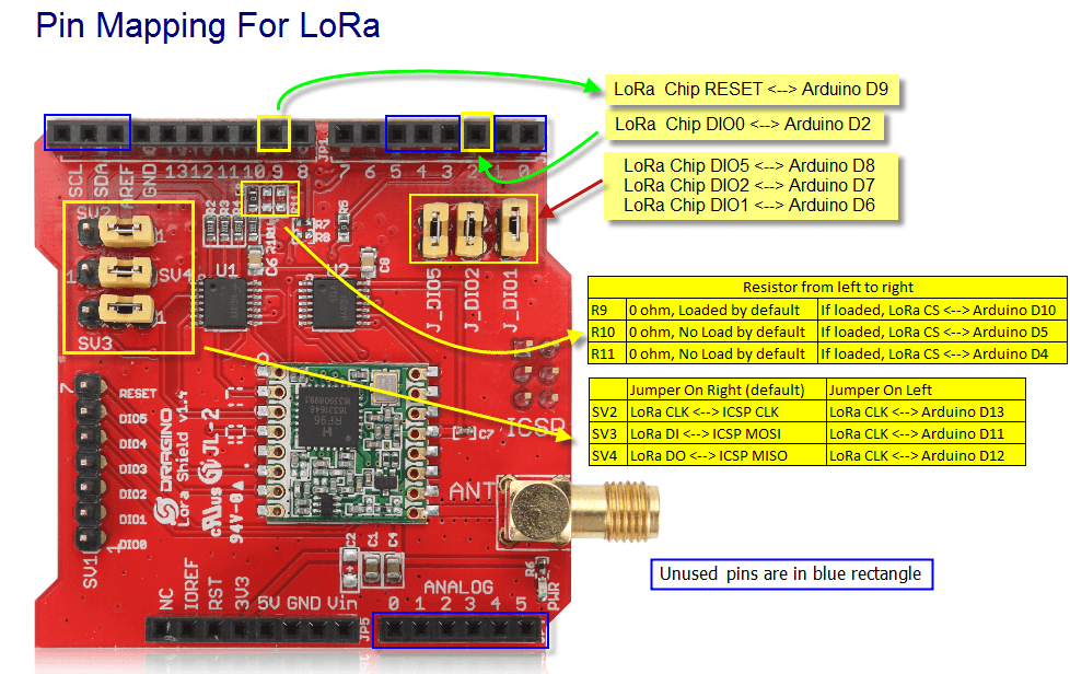
Dragino LoRa Shield for Arduino pins
I have left the TinyCLR V1 configuration in for backward compatibility
When I ran the application in Visual Studio I could reliably read the RegVersion register.
The thread '<No Name>' (0x2) has exited with code 0 (0x0).
Value = 0x00-12
Value = 0x00-12
Value = 0x00-12
Value = 0x00-12
Value = 0x00-12
Value = 0x00-12
The program '[5] TinyCLR application: Managed' has exited with code 0 (0x0).
The next step was to modify the RegisterScan project to check I could read all the SX127X configuration registers.
  class Program
   {
      static void Main()
      {
#if TINYCLR_V2_SC20100DEV
         Rfm9XDevice rfm9XDevice = new Rfm9XDevice(SC20100.SpiBus.Spi3, SC20100.GpioPin.PA13);
#endif
#if TINYCLR_V2_FEZDUINO
         Rfm9XDevice rfm9XDevice = new Rfm9XDevice(SC20100.SpiBus.Spi6, SC20100.GpioPin.PB1);
#endif

         while (true)
         {
            for (byte registerIndex = 0; registerIndex <= 0x42; registerIndex++)
            {
               byte registerValue = rfm9XDevice.RegisterReadByte(registerIndex);

               Debug.WriteLine($"Register 0x{registerIndex:x2} - Value 0X{registerValue:x2}");
            }
            Debug.WriteLine("");

            Thread.Sleep(10000);
         }
      }
   }
When I ran the application in Visual Studio I could reliably read the registers 0x00 through 0x42.
The thread '<No Name>' (0x2) has exited with code 0 (0x0).
Register 0x00 - Value 0X00
Register 0x01 - Value 0X09
Register 0x02 - Value 0X1a
Register 0x03 - Value 0X0b
Register 0x04 - Value 0X00
Register 0x05 - Value 0X52
Register 0x06 - Value 0X6c
Register 0x07 - Value 0X80
Register 0x08 - Value 0X00
Register 0x09 - Value 0X4f
Register 0x0a - Value 0X09
Register 0x0b - Value 0X2b
Register 0x0c - Value 0X20
Register 0x0d - Value 0X08
Register 0x0e - Value 0X02
Register 0x0f - Value 0X0a
Register 0x10 - Value 0Xff
Register 0x11 - Value 0X71
Register 0x12 - Value 0X15
Register 0x13 - Value 0X0b
Register 0x14 - Value 0X28
Register 0x15 - Value 0X0c
Register 0x16 - Value 0X12
Register 0x17 - Value 0X47
Register 0x18 - Value 0X32
Register 0x19 - Value 0X3e
Register 0x1a - Value 0X00
Register 0x1b - Value 0X00
Register 0x1c - Value 0X00
Register 0x1d - Value 0X00
Register 0x1e - Value 0X00
Register 0x1f - Value 0X40
Register 0x20 - Value 0X00
Register 0x21 - Value 0X00
Register 0x22 - Value 0X00
Register 0x23 - Value 0X00
Register 0x24 - Value 0X05
Register 0x25 - Value 0X00
Register 0x26 - Value 0X03
Register 0x27 - Value 0X93
Register 0x28 - Value 0X55
Register 0x29 - Value 0X55
Register 0x2a - Value 0X55
Register 0x2b - Value 0X55
Register 0x2c - Value 0X55
Register 0x2d - Value 0X55
Register 0x2e - Value 0X55
Register 0x2f - Value 0X55
Register 0x30 - Value 0X90
Register 0x31 - Value 0X40
Register 0x32 - Value 0X40
Register 0x33 - Value 0X00
Register 0x34 - Value 0X00
Register 0x35 - Value 0X0f
Register 0x36 - Value 0X00
Register 0x37 - Value 0X00
Register 0x38 - Value 0X00
Register 0x39 - Value 0Xf5
Register 0x3a - Value 0X20
Register 0x3b - Value 0X82
Register 0x3c - Value 0Xfb
Register 0x3d - Value 0X02
Register 0x3e - Value 0X80
Register 0x3f - Value 0X40
Register 0x40 - Value 0X00
Register 0x41 - Value 0X00
Register 0x42 - Value 0X12
The next step was to modify the RegisterReadAndWrite project to check I could read and write the SX127X configuration registers.
     class Program
   {
      static void Main()
      {
#if TINYCLR_V2_SC20100DEV
         Rfm9XDevice rfm9XDevice = new Rfm9XDevice(SC20100.SpiBus.Spi3, SC20100.GpioPin.PA13, SC20100.GpioPin.PA14);
#endif
#if TINYCLR_V2_FEZDUINO
         Rfm9XDevice rfm9XDevice = new Rfm9XDevice(SC20100.SpiBus.Spi6, SC20100.GpioPin.PB1, SC20100.GpioPin.PA15);
#endif

         rfm9XDevice.RegisterDump();

         while (true)
         {
            Debug.WriteLine("Read RegOpMode (read byte)");
            Byte regOpMode1 = rfm9XDevice.RegisterReadByte(0x1);
            Debug.WriteLine($"RegOpMode 0x{regOpMode1:x2}");

            Debug.WriteLine("Set LoRa mode and sleep mode (write byte)");
            rfm9XDevice.RegisterWriteByte(0x01, 0b10000000);

            Debug.WriteLine("Read RegOpMode (read byte)");
            Byte regOpMode2 = rfm9XDevice.RegisterReadByte(0x1);
            Debug.WriteLine($"RegOpMode 0x{regOpMode2:x2}");

            Debug.WriteLine("Read the preamble (read word)");
            ushort preamble = rfm9XDevice.RegisterReadWord(0x20);
            Debug.WriteLine($"Preamble 0x{preamble:x2}");

            Debug.WriteLine("Set the preamble to 0x80 (write word)");
            rfm9XDevice.RegisterWriteWord(0x20, 0x80);

            Debug.WriteLine("Read the center frequency (read byte array)");
            byte[] frequencyReadBytes = rfm9XDevice.RegisterRead(0x06, 3);
            Debug.WriteLine($"Frequency Msb 0x{frequencyReadBytes[0]:x2} Mid 0x{frequencyReadBytes[1]:x2} Lsb 0x{frequencyReadBytes[2]:x2}");

            Debug.WriteLine("Set the center frequency to 915MHz (write byte array)");
            byte[] frequencyWriteBytes = { 0xE4, 0xC0, 0x00 };
            rfm9XDevice.RegisterWrite(0x06, frequencyWriteBytes);

            rfm9XDevice.RegisterDump();

            Thread.Sleep(30000);
         }
      }
When I ran the application in Visual Studio I could read and write register values.
The thread '<No Name>' (0x2) has exited with code 0 (0x0).
Register dump
Register 0x00 - Value 0X00
Register 0x01 - Value 0X09
Register 0x02 - Value 0X1a
Register 0x03 - Value 0X0b
Register 0x04 - Value 0X00
Register 0x05 - Value 0X52
Register 0x06 - Value 0X6c
Register 0x07 - Value 0X80
Register 0x08 - Value 0X00
Register 0x09 - Value 0X4f
Register 0x0a - Value 0X09
Register 0x0b - Value 0X2b
Register 0x0c - Value 0X20
Register 0x0d - Value 0X08
Register 0x0e - Value 0X02
Register 0x0f - Value 0X0a
Register 0x10 - Value 0Xff
Register 0x11 - Value 0X71
Register 0x12 - Value 0X15
Register 0x13 - Value 0X0b
Register 0x14 - Value 0X28
Register 0x15 - Value 0X0c
Register 0x16 - Value 0X12
Register 0x17 - Value 0X47
Register 0x18 - Value 0X32
Register 0x19 - Value 0X3e
Register 0x1a - Value 0X00
Register 0x1b - Value 0X00
Register 0x1c - Value 0X00
Register 0x1d - Value 0X00
Register 0x1e - Value 0X00
Register 0x1f - Value 0X40
Register 0x20 - Value 0X00
Register 0x21 - Value 0X00
Register 0x22 - Value 0X00
Register 0x23 - Value 0X00
Register 0x24 - Value 0X05
Register 0x25 - Value 0X00
Register 0x26 - Value 0X03
Register 0x27 - Value 0X93
Register 0x28 - Value 0X55
Register 0x29 - Value 0X55
Register 0x2a - Value 0X55
Register 0x2b - Value 0X55
Register 0x2c - Value 0X55
Register 0x2d - Value 0X55
Register 0x2e - Value 0X55
Register 0x2f - Value 0X55
Register 0x30 - Value 0X90
Register 0x31 - Value 0X40
Register 0x32 - Value 0X40
Register 0x33 - Value 0X00
Register 0x34 - Value 0X00
Register 0x35 - Value 0X0f
Register 0x36 - Value 0X00
Register 0x37 - Value 0X00
Register 0x38 - Value 0X00
Register 0x39 - Value 0Xf5
Register 0x3a - Value 0X20
Register 0x3b - Value 0X82
Register 0x3c - Value 0Xfa
Register 0x3d - Value 0X02
Register 0x3e - Value 0X80
Register 0x3f - Value 0X40
Register 0x40 - Value 0X00
Register 0x41 - Value 0X00
Register 0x42 - Value 0X12
Read RegOpMode (read byte)
RegOpMode 0x09
Set LoRa mode and sleep mode (write byte)
Read RegOpMode (read byte)
RegOpMode 0x80
Read the preamble (read word)
Preamble 0x08
Set the preamble to 0x80 (write word)
Read the center frequency (read byte array)
Frequency Msb 0x6c Mid 0x80 Lsb 0x00
Set the center frequency to 915MHz (write byte array)
Register dump
Register 0x00 - Value 0Xc3
Register 0x01 - Value 0X80
Register 0x02 - Value 0X1a
Register 0x03 - Value 0X0b
Register 0x04 - Value 0X00
Register 0x05 - Value 0X52
Register 0x06 - Value 0Xe4
Register 0x07 - Value 0Xc0
Register 0x08 - Value 0X00
Register 0x09 - Value 0X4f
Register 0x0a - Value 0X09
Register 0x0b - Value 0X2b
Register 0x0c - Value 0X20
Register 0x0d - Value 0X01
Register 0x0e - Value 0X80
Register 0x0f - Value 0X00
Register 0x10 - Value 0X00
Register 0x11 - Value 0X00
Register 0x12 - Value 0X00
Register 0x13 - Value 0X00
Register 0x14 - Value 0X00
Register 0x15 - Value 0X00
Register 0x16 - Value 0X00
Register 0x17 - Value 0X00
Register 0x18 - Value 0X10
Register 0x19 - Value 0X00
Register 0x1a - Value 0X00
Register 0x1b - Value 0X00
Register 0x1c - Value 0X00
Register 0x1d - Value 0X72
Register 0x1e - Value 0X70
Register 0x1f - Value 0X64
Register 0x20 - Value 0X80
Register 0x21 - Value 0X00
Register 0x22 - Value 0X01
Register 0x23 - Value 0Xff
Register 0x24 - Value 0X00
Register 0x25 - Value 0X00
Register 0x26 - Value 0X04
Register 0x27 - Value 0X00
Register 0x28 - Value 0X00
Register 0x29 - Value 0X00
Register 0x2a - Value 0X00
Register 0x2b - Value 0X00
Register 0x2c - Value 0X00
Register 0x2d - Value 0X50
Register 0x2e - Value 0X14
Register 0x2f - Value 0X45
Register 0x30 - Value 0X55
Register 0x31 - Value 0Xc3
Register 0x32 - Value 0X05
Register 0x33 - Value 0X27
Register 0x34 - Value 0X1c
Register 0x35 - Value 0X0a
Register 0x36 - Value 0X03
Register 0x37 - Value 0X0a
Register 0x38 - Value 0X42
Register 0x39 - Value 0X12
Register 0x3a - Value 0X49
Register 0x3b - Value 0X1d
Register 0x3c - Value 0X00
Register 0x3d - Value 0Xaf
Register 0x3e - Value 0X00
Register 0x3f - Value 0X00
Register 0x40 - Value 0X00
Register 0x41 - Value 0X00
Register 0x42 - Value 0X12
At this point I was confident that I could hardware reset the shield and read/modify registers on the SX127X.
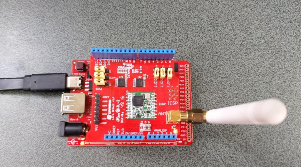
STM32F429 Discovery+ Dragino LoRa shield with Armtronix device
The code now works on STM32F429 Discovery and ESP32 WROOM platforms. (manual update nanoFramework.Hardware.Esp32 NuGet reference required)
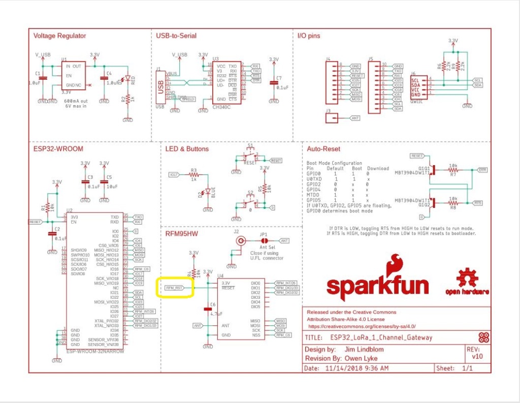
Sparkfun LoRa Gateway 1 Channel schematic
One disadvantage of the SparkFun device is that the reset pin on the SX127X doesn’t appear to be connected to the ESP32 so I can’t factory reset the device in code.
//#define ST_STM32F429I_DISCOVERY //nanoff --target ST_STM32F429I_DISCOVERY --update
#define ESP32_WROOM_32_LORA_1_CHANNEL //nanoff --target ESP32_WROOM_32 --serialport COM4 --update
namespace devMobile.IoT.Rfm9x.TransmitBasic
{
using System;
using System.Text;
using System.Threading;
using Windows.Devices.Gpio;
using Windows.Devices.Spi;
#if ESP32_WROOM_32_LORA_1_CHANNEL
using nanoFramework.Hardware.Esp32;
#endif
public sealed class Rfm9XDevice
{
private SpiDevice rfm9XLoraModem;
private const byte RegisterAddressReadMask = 0X7f;
private const byte RegisterAddressWriteMask = 0x80;
public Rfm9XDevice(string spiPort, int chipSelectPin, int resetPin)
{
var settings = new SpiConnectionSettings(chipSelectPin)
{
ClockFrequency = 1000000,
//DataBitLength = 8,
Mode = SpiMode.Mode0,// From SemTech docs pg 80 CPOL=0, CPHA=0
SharingMode = SpiSharingMode.Shared,
};
rfm9XLoraModem = SpiDevice.FromId(spiPort, settings);
// Factory reset pin configuration
GpioController gpioController = GpioController.GetDefault();
GpioPin resetGpioPin = gpioController.OpenPin(resetPin);
resetGpioPin.SetDriveMode(GpioPinDriveMode.Output);
resetGpioPin.Write(GpioPinValue.Low);
Thread.Sleep(10);
resetGpioPin.Write(GpioPinValue.High);
Thread.Sleep(10);
}
public Rfm9XDevice(string spiPort, int chipSelectPin)
{
var settings = new SpiConnectionSettings(chipSelectPin)
{
ClockFrequency = 1000000,
Mode = SpiMode.Mode0,// From SemTech docs pg 80 CPOL=0, CPHA=0
SharingMode = SpiSharingMode.Shared,
};
rfm9XLoraModem = SpiDevice.FromId(spiPort, settings);
}
public Byte RegisterReadByte(byte registerAddress)
{
byte[] writeBuffer = new byte[] { registerAddress &= RegisterAddressReadMask, 0x0 };
byte[] readBuffer = new byte[writeBuffer.Length];
rfm9XLoraModem.TransferFullDuplex(writeBuffer, readBuffer);
return readBuffer[1];
}
public ushort RegisterReadWord(byte address)
{
byte[] writeBuffer = new byte[] { address &= RegisterAddressReadMask, 0x0, 0x0 };
byte[] readBuffer = new byte[writeBuffer.Length];
rfm9XLoraModem.TransferFullDuplex(writeBuffer, readBuffer);
return (ushort)(readBuffer[2] + (readBuffer[1] << 8));
}
public byte[] RegisterRead(byte address, int length)
{
byte[] writeBuffer = new byte[length + 1];
byte[] readBuffer = new byte[writeBuffer.Length];
byte[] repyBuffer = new byte[length];
writeBuffer[0] = address &= RegisterAddressReadMask;
rfm9XLoraModem.TransferFullDuplex(writeBuffer, readBuffer);
Array.Copy(readBuffer, 1, repyBuffer, 0, length);
return repyBuffer;
}
public void RegisterWriteByte(byte address, byte value)
{
byte[] writeBuffer = new byte[] { address |= RegisterAddressWriteMask, value };
byte[] readBuffer = new byte[writeBuffer.Length];
rfm9XLoraModem.TransferFullDuplex(writeBuffer, readBuffer);
}
public void RegisterWriteWord(byte address, ushort value)
{
byte[] valueBytes = BitConverter.GetBytes(value);
byte[] writeBuffer = new byte[] { address |= RegisterAddressWriteMask, valueBytes[0], valueBytes[1] };
byte[] readBuffer = new byte[writeBuffer.Length];
rfm9XLoraModem.TransferFullDuplex(writeBuffer,readBuffer);
}
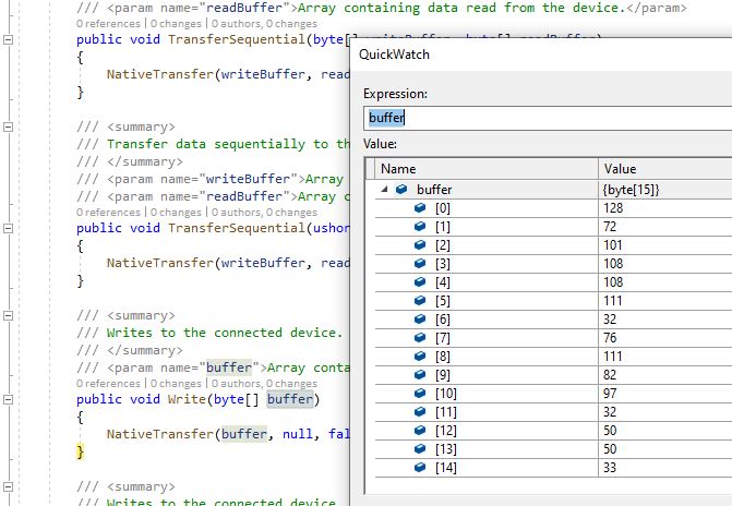
public void RegisterWrite(byte address, byte[] bytes)
{
byte[] writeBuffer = new byte[1 + bytes.Length];
byte[] readBuffer = new byte[writeBuffer.Length];
Array.Copy(bytes, 0, writeBuffer, 1, bytes.Length);
writeBuffer[0] = address |= RegisterAddressWriteMask;
rfm9XLoraModem.TransferFullDuplex(writeBuffer, readBuffer);
}
public void RegisterDump()
{
Console.WriteLine("Register dump");
for (byte registerIndex = 0; registerIndex <= 0x42; registerIndex++)
{
byte registerValue = this.RegisterReadByte(registerIndex);
Console.WriteLine($"Register 0x{registerIndex:x2} - Value 0X{registerValue:x2}");
}
}
}
class Program
{
#if ST_STM32F429I_DISCOVERY
private const string SpiBusId = "SPI5";
#endif
#if ESP32_WROOM_32_LORA_1_CHANNEL
private const string SpiBusId = "SPI1";
#endif
static void Main()
{
int SendCount = 0;
#if ST_STM32F429I_DISCOVERY
int chipSelectPinNumber = PinNumber('C', 2);
int resetPinNumber = PinNumber('C', 3);
#endif
#if ESP32_WROOM_32_LORA_1_CHANNEL
int chipSelectPinNumber = Gpio.IO16;
#endif
try
{
#if ESP32_WROOM_32_LORA_1_CHANNEL
Configuration.SetPinFunction(Gpio.IO12, DeviceFunction.SPI1_MISO);
Configuration.SetPinFunction(Gpio.IO13, DeviceFunction.SPI1_MOSI);
Configuration.SetPinFunction(Gpio.IO14, DeviceFunction.SPI1_CLOCK);
Rfm9XDevice rfm9XDevice = new Rfm9XDevice(SpiBusId, chipSelectPinNumber);
#endif
#if ST_STM32F429I_DISCOVERY
Rfm9XDevice rfm9XDevice = new Rfm9XDevice(SpiBusId, chipSelectPinNumber, resetPinNumber);
#endif
Thread.Sleep(500);
// Put device into LoRa + Standby mode
rfm9XDevice.RegisterWriteByte(0x01, 0b10000001); // RegOpMode
// Set the frequency to 915MHz
byte[] frequencyWriteBytes = { 0xE4, 0xC0, 0x00 }; // RegFrMsb, RegFrMid, RegFrLsb
rfm9XDevice.RegisterWrite(0x06, frequencyWriteBytes);
// More power PA Boost
rfm9XDevice.RegisterWriteByte(0x09, 0b10000000); // RegPaConfig
rfm9XDevice.RegisterDump();
while (true)
{
rfm9XDevice.RegisterWriteByte(0x0E, 0x0); // RegFifoTxBaseAddress
// Set the Register Fifo address pointer
rfm9XDevice.RegisterWriteByte(0x0D, 0x0); // RegFifoAddrPtr
string messageText = $"Hello LoRa {SendCount += 1}!";
// load the message into the fifo
byte[] messageBytes = UTF8Encoding.UTF8.GetBytes(messageText);
rfm9XDevice.RegisterWrite(0x0, messageBytes); // RegFifo
// Set the length of the message in the fifo
rfm9XDevice.RegisterWriteByte(0x22, (byte)messageBytes.Length); // RegPayloadLength
Console.WriteLine($"Sending {messageBytes.Length} bytes message {messageText}");
/// Set the mode to LoRa + Transmit
rfm9XDevice.RegisterWriteByte(0x01, 0b10000011); // RegOpMode
// Wait until send done, no timeouts in PoC
Console.WriteLine("Send-wait");
byte IrqFlags = rfm9XDevice.RegisterReadByte(0x12); // RegIrqFlags
while ((IrqFlags & 0b00001000) == 0) // wait until TxDone cleared
{
Thread.Sleep(10);
IrqFlags = rfm9XDevice.RegisterReadByte(0x12); // RegIrqFlags
Console.WriteLine(".");
}
Console.WriteLine("");
rfm9XDevice.RegisterWriteByte(0x12, 0b00001000); // clear TxDone bit
Console.WriteLine("Send-Done");
Thread.Sleep(10000);
}
}
catch (Exception ex)
{
Console.WriteLine(ex.Message);
}
}
#if ST_STM32F429I_DISCOVERY
static int PinNumber(char port, byte pin)
{
if (port < 'A' || port > 'J')
throw new ArgumentException();
return ((port - 'A') * 16) + pin;
}
#endif
}
}
When I initially ran the application in Visual Studio 2019 the text below was displayed in the output window.
Register dump
Register 0x00 - Value 0X00
Register 0x01 - Value 0X80
Register 0x02 - Value 0X1A
Register 0x03 - Value 0X0B
Register 0x04 - Value 0X00
…
Register 0x3E - Value 0X00
Register 0x3F - Value 0X00
Register 0x40 - Value 0X00
Register 0x41 - Value 0X00
Register 0x42 - Value 0X12
Sending 13 bytes message Hello LoRa 1!
Send-wait
.
.
.
.
.
Send-Done
Sending 13 bytes message Hello LoRa 2!
Send-wait
.
.
.
.
.
Send-Done
I could the see the messages arriving at the Armtronix device in the Arduino monitor.
The first message was getting corrupted (only when running in the debugger) which after some trial and error I think was most probably due to my RegOpMode register mode configuration.
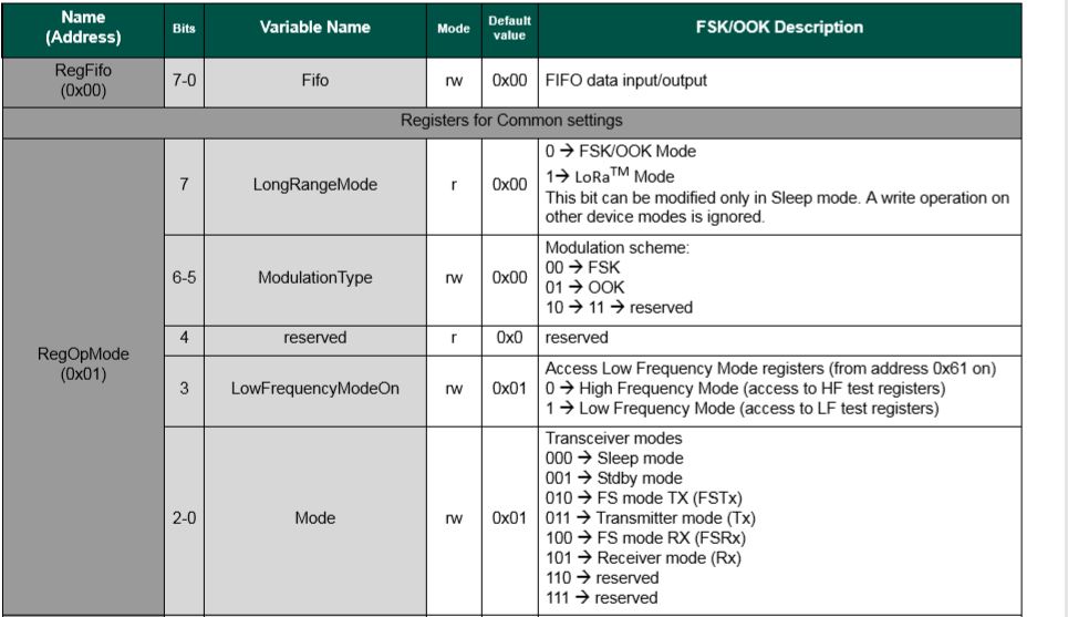
SX127X RegOpMode details
// Put device into LoRa + Sleep mode
rfm9XDevice.RegisterWriteByte(0x01, 0b10000000);

// Put device into LoRa + Standby mode
rfm9XDevice.RegisterWriteByte(0x01, 0b10000001);
After a couple of years and half a dozen platform ports still finding bugs in my samples…
The SC20100 receive application configures the SX127X, polls a status register to looking to see if a message has arrived, displays it as text and then goes back to waiting.
   class Program
   {
      static void Main()
      {
         Rfm9XDevice rfm9XDevice = new Rfm9XDevice(SC20100.SpiBus.Spi3, SC20100.GpioPin.PA13, SC20100.GpioPin.PA14);

         // Put device into LoRa + Sleep mode
         rfm9XDevice.RegisterWriteByte(0x01, 0b10000000); // RegOpMode

         // Set the frequency to 915MHz
         byte[] frequencyWriteBytes = { 0xE4, 0xC0, 0x00 }; // RegFrMsb, RegFrMid, RegFrLsb
         rfm9XDevice.RegisterWrite(0x06, frequencyWriteBytes);

         rfm9XDevice.RegisterWriteByte(0x0F, 0x0); // RegFifoRxBaseAddress

         rfm9XDevice.RegisterWriteByte(0x01, 0b10000101); // RegOpMode set LoRa & RxContinuous

         while (true)
         {
            // Wait until a packet is received, no timeouts in PoC
            Debug.WriteLine("Receive-Wait");
            byte irqFlags = rfm9XDevice.RegisterReadByte(0x12); // RegIrqFlags
            while ((irqFlags & 0b01000000) == 0)  // wait until RxDone cleared
            {
               Thread.Sleep(100);
               irqFlags = rfm9XDevice.RegisterReadByte(0x12); // RegIrqFlags
               //Debug.Write(".");
            }
            Debug.WriteLine("");
            Debug.WriteLine($"RegIrqFlags 0X{irqFlags:X2}");
            Debug.WriteLine("Receive-Message");
            byte currentFifoAddress = rfm9XDevice.RegisterReadByte(0x10); // RegFifiRxCurrent
            rfm9XDevice.RegisterWriteByte(0x0d, currentFifoAddress); // RegFifoAddrPtr

            byte numberOfBytes = rfm9XDevice.RegisterReadByte(0x13); // RegRxNbBytes

            byte[] messageBytes = rfm9XDevice.RegisterRead(0x00, numberOfBytes); // RegFifo

            rfm9XDevice.RegisterWriteByte(0x0d, 0);
            rfm9XDevice.RegisterWriteByte(0x12, 0b11111111); // RegIrqFlags clear all the bits

            string messageText = UTF8Encoding.UTF8.GetString(messageBytes);
            Debug.WriteLine($"Received {messageBytes.Length} byte message {messageText}");

            Debug.WriteLine("Receive-Done");
         }
      }
   }
When I ran the SC20100 application in Visual Studio
'GHIElectronics.TinyCLR.VisualStudio.ProjectSystem.dll' (Managed): Loaded 'C:\Users\BrynLewis\source\repos\RFM9X.TinyCLR\ReceiveBasic\bin\Debug\pe\..\ReceiveBasic.exe', Symbols loaded.
The thread '<No Name>' (0x2) has exited with code 0 (0x0).
Receive-Wait

RegIrqFlags 0X50
Receive-Message
Received 16 byte message HeLoRa World! 74
Receive-Done
Receive-Wait

RegIrqFlags 0X50
Receive-Message
Received 59 byte message  �LoRaIoT1Maduino2at 64.6,ah 66,wsa 2,wsg 3,wd 37.13,r 0.00,
Receive-Done
Receive-Wait

RegIrqFlags 0X50
Receive-Message
Received 16 byte message HeLoRa World! 76
Receive-Done
Receive-Wait

RegIrqFlags 0X50
Receive-Message
Received 16 byte message HeLoRa World! 78
Receive-Done
Receive-Wait
I could the see the messages arriving at the Armtronix device in the Arduino monitor.
STM32F429 Discovery+ Dragino LoRa shield with Armtronix device
/*
  LoRa Duplex communication with Sync Word

  Sends a message every half second, and polls continually
  for new incoming messages. Sets the LoRa radio's Sync Word.

  Spreading factor is basically the radio's network ID. Radios with different
  Sync Words will not receive each other's transmissions. This is one way you
  can filter out radios you want to ignore, without making an addressing scheme.

  See the Semtech datasheet, http://www.semtech.com/images/datasheet/sx1276.pdf
  for more on Sync Word.

  created 28 April 2017
  by Tom Igoe
*/
#include <stdlib.h>
#include <LoRa.h>
const int csPin = PA4;          // LoRa radio chip select
const int resetPin = PC13;       // LoRa radio reset
const int irqPin = PA11;         // change for your board; must be a hardware interrupt pin

byte msgCount = 0;            // count of outgoing messages
int interval = 2000;          // interval between sends
long lastSendTime = 0;        // time of last packet send

void setup() {
  Serial.begin(9600);                   // initialize serial
  while (!Serial);

  Serial.println("LoRa Duplex - Set sync word");

  // override the default CS, reset, and IRQ pins (optional)
  LoRa.setPins(csPin, resetPin, irqPin);// set CS, reset, IRQ pin

  if (!LoRa.begin(915E6)) {             // initialize ratio at 915 MHz
    Serial.println("LoRa init failed. Check your connections.");
    while (true);                       // if failed, do nothing
  }

  LoRa.setSyncWord(0x12);           // ranges from 0-0xFF, default 0x34, see API docs

  LoRa.dumpRegisters(Serial);
  Serial.println("LoRa init succeeded.");
}

void loop() {
  if (millis() - lastSendTime > interval) {
    String message = "HeLoRa World! ";   // send a message
    message += msgCount;
    sendMessage(message);
    Serial.println("Sending " + message);
    lastSendTime = millis();            // timestamp the message
    interval = random(1000) + 10000;    // 10-11 seconds
    msgCount++;
  }

  // parse for a packet, and call onReceive with the result:
  onReceive(LoRa.parsePacket());
}

void sendMessage(String outgoing) {
  LoRa.beginPacket();                   // start packet
  LoRa.print(outgoing);                 // add payload
  LoRa.endPacket();                     // finish packet and send it
  msgCount++;                           // increment message ID
}

void onReceive(int packetSize) {
  if (packetSize == 0) return;          // if there's no packet, return

  // read packet header bytes:
  String incoming = "";

  while (LoRa.available()) {
    incoming += (char)LoRa.read();
  }

  Serial.println("Message: " + incoming);
  Serial.println("RSSI: " + String(LoRa.packetRssi()));
  Serial.println("Snr: " + String(LoRa.packetSnr()));
  Serial.println();
}
The STM32F429 Discovery application
namespace devMobile.IoT.Rfm9x.TransmitBasic
{
   using System;
   using System.Text;
   using System.Threading;

   using Windows.Devices.Gpio;
   using Windows.Devices.Spi;

   public sealed class Rfm9XDevice
   {
      private SpiDevice rfm9XLoraModem;
      private GpioPin chipSelectGpioPin;
      private const byte RegisterAddressReadMask = 0X7f;
      private const byte RegisterAddressWriteMask = 0x80;

      public Rfm9XDevice(string spiPort, int chipSelectPin, int resetPin)
      {
         var settings = new SpiConnectionSettings(chipSelectPin)
         {
            ClockFrequency = 500000,
//            DataBitLength = 8,
            Mode = SpiMode.Mode0,// From SemTech docs pg 80 CPOL=0, CPHA=0
            SharingMode = SpiSharingMode.Shared,
         };

         rfm9XLoraModem = SpiDevice.FromId(spiPort, settings);

         GpioController gpioController = GpioController.GetDefault();

         // Chip select pin configuration
         chipSelectGpioPin = gpioController.OpenPin(chipSelectPin);
         chipSelectGpioPin.SetDriveMode(GpioPinDriveMode.Output);

         // Factory reset pin configuration
         GpioPin resetGpioPin = gpioController.OpenPin(resetPin);
         resetGpioPin.SetDriveMode(GpioPinDriveMode.Output);
         resetGpioPin.Write(GpioPinValue.Low);
         Thread.Sleep(10);
         resetGpioPin.Write(GpioPinValue.High);
         Thread.Sleep(10);
      }

      public Byte RegisterReadByte(byte registerAddress)
      {
         byte[] writeBuffer = new byte[] { registerAddress &= RegisterAddressReadMask, 0x0 };
         byte[] readBuffer = new byte[writeBuffer.Length];

         rfm9XLoraModem.TransferFullDuplex(writeBuffer, readBuffer);

         return readBuffer[1];
      }

      public ushort RegisterReadWord(byte address)
      {
         byte[] writeBuffer = new byte[] { address &= RegisterAddressReadMask, 0x0, 0x0 };
         byte[] readBuffer = new byte[writeBuffer.Length];

         rfm9XLoraModem.TransferFullDuplex(writeBuffer, readBuffer);

         return (ushort)(readBuffer[2] + (readBuffer[1] << 8));
      }

      public byte[] RegisterRead(byte address, int length)
      {
         byte[] writeBuffer = new byte[length + 1];
         byte[] readBuffer = new byte[length + 1];
         byte[] repyBuffer = new byte[length];

         writeBuffer[0] = address &= RegisterAddressReadMask;

         rfm9XLoraModem.TransferFullDuplex(writeBuffer, readBuffer);

         Array.Copy(readBuffer, 1, repyBuffer, 0, length);

         return repyBuffer;
      }

      public void RegisterWriteByte(byte address, byte value)
      {
         byte[] writeBuffer = new byte[] { address |= RegisterAddressWriteMask, value };

         rfm9XLoraModem.Write(writeBuffer);
      }

      public void RegisterWriteWord(byte address, ushort value)
      {
         byte[] valueBytes = BitConverter.GetBytes(value);
         byte[] writeBuffer = new byte[] { address |= RegisterAddressWriteMask, valueBytes[0], valueBytes[1] };

         rfm9XLoraModem.Write(writeBuffer);
      }

      public void RegisterWrite(byte address, byte[] bytes)
      {
         byte[] writeBuffer = new byte[1 + bytes.Length];

         Array.Copy(bytes, 0, writeBuffer, 1, bytes.Length);
         writeBuffer[0] = address |= RegisterAddressWriteMask;

         rfm9XLoraModem.Write(writeBuffer);
      }

      public void RegisterDump()
      {
         Console.WriteLine("Register dump");
         for (byte registerIndex = 0; registerIndex <= 0x42; registerIndex++)
         {
            byte registerValue = this.RegisterReadByte(registerIndex);

            Console.WriteLine($"Register 0x{registerIndex:x2} - Value 0X{registerValue:x2}");
         }
      }
   }

   class Program
   {
      static void Main()
      {
         Rfm9XDevice rfm9XDevice = new Rfm9XDevice("SPI5", PinNumber('C', 2), PinNumber('C', 3));
         int SendCount = 0;

         // Put device into LoRa + Sleep mode
         rfm9XDevice.RegisterWriteByte(0x01, 0b10000000); // RegOpMode

         // Set the frequency to 915MHz
         byte[] frequencyWriteBytes = { 0xE4, 0xC0, 0x00 }; // RegFrMsb, RegFrMid, RegFrLsb
         rfm9XDevice.RegisterWrite(0x06, frequencyWriteBytes);

         // More power PA Boost
         rfm9XDevice.RegisterWriteByte(0x09, 0b10000000); // RegPaConfig

         rfm9XDevice.RegisterDump();

         while (true)
         {
            rfm9XDevice.RegisterWriteByte(0x0E, 0x0); // RegFifoTxBaseAddress

            // Set the Register Fifo address pointer
            rfm9XDevice.RegisterWriteByte(0x0D, 0x0); // RegFifoAddrPtr

            string messageText = $"Hello LoRa {SendCount += 1}!";

            // load the message into the fifo
            byte[] messageBytes = UTF8Encoding.UTF8.GetBytes(messageText);
            rfm9XDevice.RegisterWrite(0x0, messageBytes); // RegFifo

            // Set the length of the message in the fifo
            rfm9XDevice.RegisterWriteByte(0x22, (byte)messageBytes.Length); // RegPayloadLength

            Console.WriteLine($"Sending {messageBytes.Length} bytes message {messageText}");
            /// Set the mode to LoRa + Transmit
            rfm9XDevice.RegisterWriteByte(0x01, 0b10000011); // RegOpMode

            // Wait until send done, no timeouts in PoC
            Console.WriteLine("Send-wait");
            byte IrqFlags = rfm9XDevice.RegisterReadByte(0x12); // RegIrqFlags
            while ((IrqFlags & 0b00001000) == 0)  // wait until TxDone cleared
            {
               Thread.Sleep(10);
               IrqFlags = rfm9XDevice.RegisterReadByte(0x12); // RegIrqFlags
               Console.WriteLine(".");
            }
            rfm9XDevice.RegisterWriteByte(0x12, 0b00001000); // clear TxDone bit
            Console.WriteLine("Send-Done");

            Thread.Sleep(10000);
         }
      }

      static int PinNumber(char port, byte pin)
      {
         if (port < 'A' || port > 'J')
            throw new ArgumentException();

         return ((port - 'A') * 16) + pin;
      }
   }