Random wanderings through Microsoft Azure esp. PaaS plumbing, the IoT bits, AI on Micro controllers, AI on Edge Devices, .NET nanoFramework, .NET Core on *nix and ML.NET+ONNX
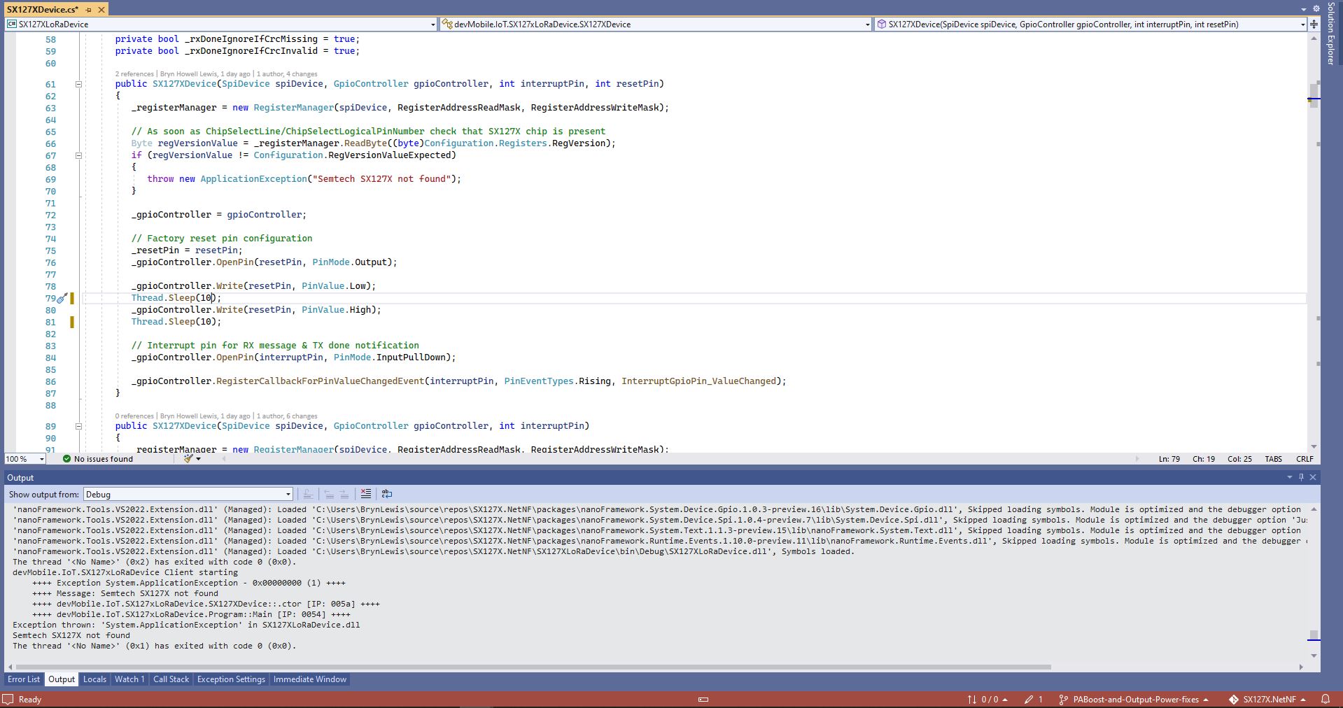
One afternoon the issue occurred several times in a row, the application wouldn’t startup because the SX127X device detection failed and message transmission was also not being confirmed.(TX Done).
Visual Studio output windows with SX127X detection failure
Visual Studio output windows with no Transmit confirmations
public SX127XDevice(SpiDevice spiDevice, GpioController gpioController, int interruptPin, int resetPin)
{
	_gpioController = gpioController;

	// Factory reset pin configuration
	_resetPin = resetPin;
	_gpioController.OpenPin(resetPin, PinMode.Output);

	_gpioController.Write(resetPin, PinValue.Low);
	Thread.Sleep(20);
	_gpioController.Write(resetPin, PinValue.High);
	Thread.Sleep(100);

	_registerManager = new RegisterManager(spiDevice, RegisterAddressReadMask, RegisterAddressWriteMask);

	// Once the pins setup check that SX127X chip is present
	Byte regVersionValue = _registerManager.ReadByte((byte)Configuration.Registers.RegVersion);
	if (regVersionValue != Configuration.RegVersionValueExpected)
	{
		throw new ApplicationException("Semtech SX127X not found");
	}

	// Interrupt pin for RX message & TX done notification
	_gpioController.OpenPin(interruptPin, PinMode.InputPullDown);

	_gpioController.RegisterCallbackForPinValueChangedEvent(interruptPin, PinEventTypes.Rising, InterruptGpioPin_ValueChanged);
}
I could single step through the code and inspect variables with the debugger and it looks like a timing issue with order of the strobing of the reset pin and the initialisation of the RegisterManager. I’ll spend and hour starting and stopping the application, then smoke test the code for 24 hours with a couple of other devices generating traffic just to check.
namespace devMobile.IoT.SX127xLoRaDevice
{
	using System;
	using System.Text;
	using System.Threading;

	class Program
	{
		private const double Frequency = 915000000.0;
#if ESP32_WROOM_32_LORA_1_CHANNEL
      private const int SpiBusId = 1;
#endif
#if NETDUINO3_WIFI
		private const int SpiBusId = 2;
#endif
#if ST_STM32F769I_DISCOVERY
		private const int SpiBusId = 2;
#endif
		private static SX127XDevice sx127XDevice;

		static void Main(string[] args)
		{
			int SendCount = 0;
#if ESP32_WROOM_32_LORA_1_CHANNEL // No reset line for this device as it isn't connected on SX127X
			int chipSelectLine = Gpio.IO16;
			int interruptPinNumber = Gpio.IO26;
#endif
#if NETDUINO3_WIFI
			// Arduino D10->PB10
			int chipSelectLine = PinNumber('B', 10);
			// Arduino D9->PE5
			int resetPinNumber = PinNumber('E', 5);
			// Arduino D2 -PA3
			int interruptPinNumber = PinNumber('A', 3);
#endif
#if ST_STM32F769I_DISCOVERY
			// Arduino D10->PA11
			int chipSelectLine = PinNumber('A', 11);
			// Arduino D9->PH6
			int resetPinNumber = PinNumber('H', 6);
			// Arduino D2->PA4
			int interruptPinNumber = PinNumber('J', 1);
#endif
			Console.WriteLine("devMobile.IoT.SX127xLoRaDevice Client starting");

			try
			{
#if ESP32_WROOM_32_LORA_1_CHANNEL
				Configuration.SetPinFunction(Gpio.IO12, DeviceFunction.SPI1_MISO);
				Configuration.SetPinFunction(Gpio.IO13, DeviceFunction.SPI1_MOSI);
				Configuration.SetPinFunction(Gpio.IO14, DeviceFunction.SPI1_CLOCK);

				sx127XDevice = new SX127XDevice(SpiBusId, chipSelectLine, interruptPinNumber);
#endif
#if NETDUINO3_WIFI || ST_STM32F769I_DISCOVERY
				sx127XDevice = new SX127XDevice(SpiBusId, chipSelectLine, interruptPinNumber, resetPinNumber);
#endif

				sx127XDevice.Initialise(SX127XDevice.RegOpModeMode.ReceiveContinuous,
							Frequency,
							lnaGain: SX127XDevice.RegLnaLnaGain.G3,
							lnaBoost:true,
							powerAmplifier: SX127XDevice.PowerAmplifier.PABoost,
							rxPayloadCrcOn: true,
							rxDoneignoreIfCrcMissing: false
							);

#if DEBUG
				sx127XDevice.RegisterDump();
#endif

				sx127XDevice.OnReceive += SX127XDevice_OnReceive;
				sx127XDevice.Receive();
				sx127XDevice.OnTransmit += SX127XDevice_OnTransmit;

				Thread.Sleep(500);

				while (true)
				{
					string messageText = $"Hello LoRa from .NET nanoFramework {SendCount += 1}!";

					byte[] messageBytes = UTF8Encoding.UTF8.GetBytes(messageText);
					//Console.WriteLine($"{DateTime.UtcNow:HH:mm:ss}-TX {messageBytes.Length} byte message {messageText}");
					//sx127XDevice.Send(messageBytes);

					Thread.Sleep(50000);
				}
			}
			catch (Exception ex)
			{
				Console.WriteLine(ex.Message);
			}
		}

		private static void SX127XDevice_OnReceive(object sender, SX127XDevice.OnDataReceivedEventArgs e)
		{
			try
			{
				// Remove unprintable characters from messages
				for (int index = 0; index < e.Data.Length; index++)
				{
					if ((e.Data[index] < 0x20) || (e.Data[index] > 0x7E))
					{
						e.Data[index] = 0x7C;
					}
				}

				string messageText = UTF8Encoding.UTF8.GetString(e.Data, 0, e.Data.Length);

				Console.WriteLine($"{DateTime.UtcNow:HH:mm:ss}-RX PacketSnr {e.PacketSnr:0.0} Packet RSSI {e.PacketRssi}dBm RSSI {e.Rssi}dBm = {e.Data.Length} byte message {messageText}");
			}
			catch (Exception ex)
			{
				Console.WriteLine(ex.Message);
			}
		}

		private static void SX127XDevice_OnTransmit(object sender, SX127XDevice.OnDataTransmitedEventArgs e)
		{
			sx127XDevice.SetMode(SX127XDevice.RegOpModeMode.ReceiveContinuous);

			Console.WriteLine($"{DateTime.UtcNow:HH:mm:ss}-TX Done");
		}

#if NETDUINO3_WIFI || ST_STM32F769I_DISCOVERY
		static int PinNumber(char port, byte pin)
		{
			if (port < 'A' || port > 'J')
				throw new ArgumentException();

			return ((port - 'A') * 16) + pin;
		}
#endif
	}
}
The sample application shows how to configure the library for different devices (SPI port, interrupt pin and optional reset pin) then send/receive payloads. The library is intended to be initialised then run for long periods of time (I’m looking at a month long soak test next) rather than changing configuration while running. The initialise method has many parameters which have “reasonable” default values. (Posts coming about optimising power consumption and range).
This code implements the reception of messages builds on my transmit basic sample. I had to add a simple for loop to replace un-printable characters in the received message with spaces as nanoFrameworkUTF8Encoding.UTF8.GetString was throwing exceptions.
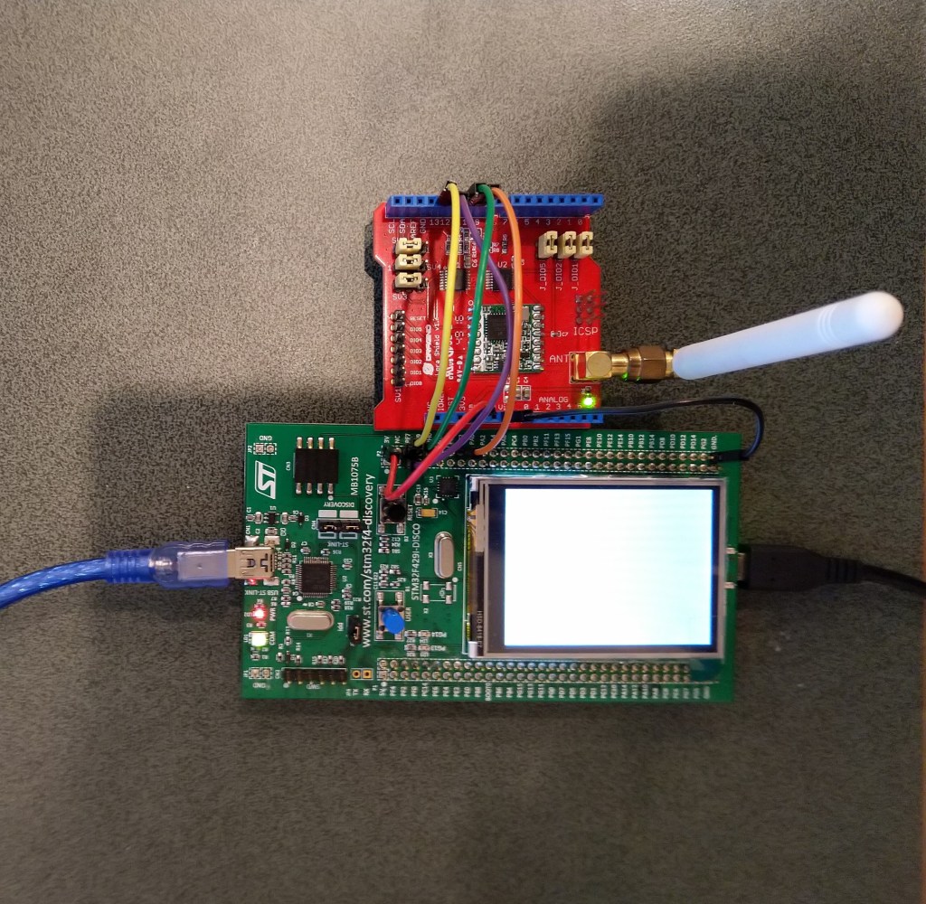
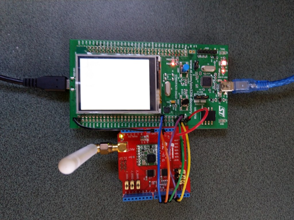
STM32F429 Discovery+ Dragino LoRa shield with Armtronix device
The code now works on STM32F429 Discovery and ESP32 WROOM platforms. (manual update nanoFramework.Hardware.Esp32 NuGet reference required)
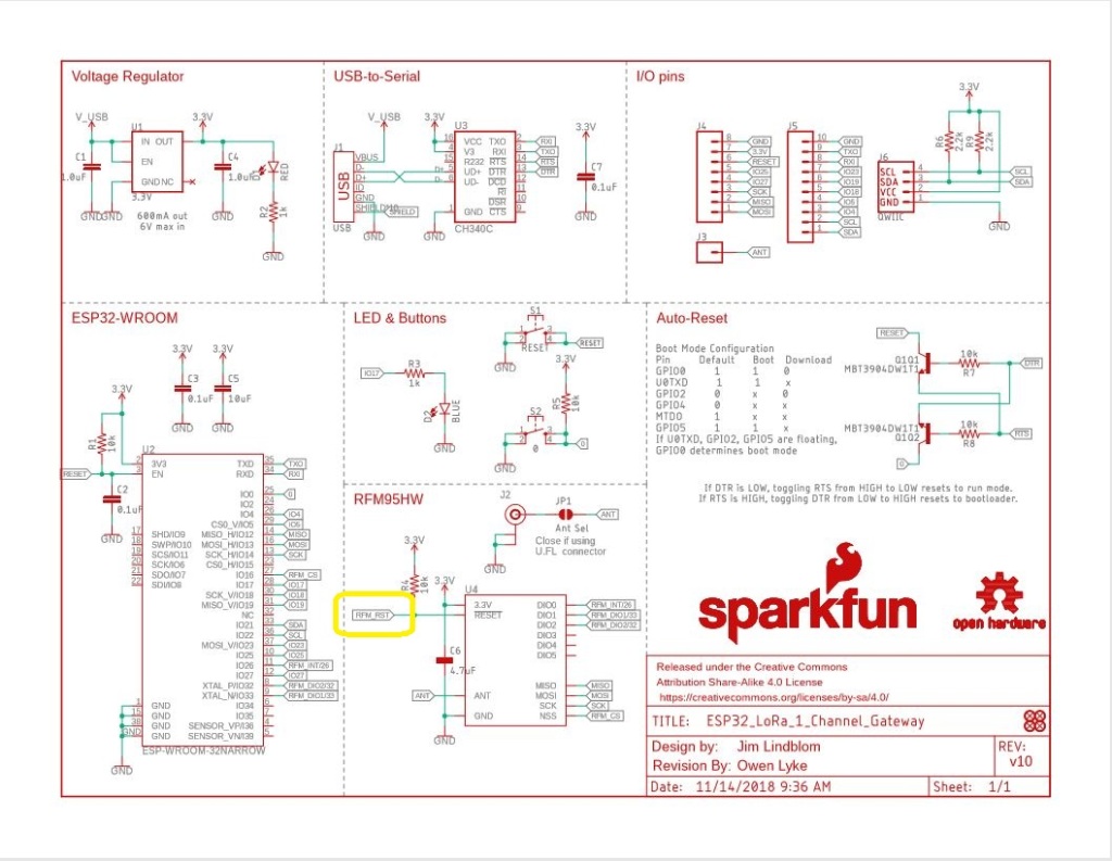
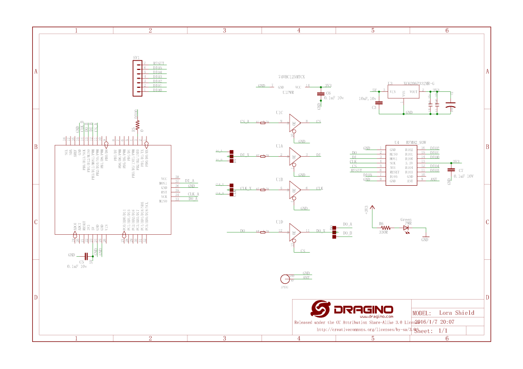
Sparkfun LoRa Gateway 1 Channel schematic
One disadvantage of the SparkFun device is that the reset pin on the SX127X doesn’t appear to be connected to the ESP32 so I can’t factory reset the device in code.
//#define ST_STM32F429I_DISCOVERY //nanoff --target ST_STM32F429I_DISCOVERY --update
#define ESP32_WROOM_32_LORA_1_CHANNEL //nanoff --target ESP32_WROOM_32 --serialport COM4 --update
namespace devMobile.IoT.Rfm9x.TransmitBasic
{
using System;
using System.Text;
using System.Threading;
using Windows.Devices.Gpio;
using Windows.Devices.Spi;
#if ESP32_WROOM_32_LORA_1_CHANNEL
using nanoFramework.Hardware.Esp32;
#endif
public sealed class Rfm9XDevice
{
private SpiDevice rfm9XLoraModem;
private const byte RegisterAddressReadMask = 0X7f;
private const byte RegisterAddressWriteMask = 0x80;
public Rfm9XDevice(string spiPort, int chipSelectPin, int resetPin)
{
var settings = new SpiConnectionSettings(chipSelectPin)
{
ClockFrequency = 1000000,
//DataBitLength = 8,
Mode = SpiMode.Mode0,// From SemTech docs pg 80 CPOL=0, CPHA=0
SharingMode = SpiSharingMode.Shared,
};
rfm9XLoraModem = SpiDevice.FromId(spiPort, settings);
// Factory reset pin configuration
GpioController gpioController = GpioController.GetDefault();
GpioPin resetGpioPin = gpioController.OpenPin(resetPin);
resetGpioPin.SetDriveMode(GpioPinDriveMode.Output);
resetGpioPin.Write(GpioPinValue.Low);
Thread.Sleep(10);
resetGpioPin.Write(GpioPinValue.High);
Thread.Sleep(10);
}
public Rfm9XDevice(string spiPort, int chipSelectPin)
{
var settings = new SpiConnectionSettings(chipSelectPin)
{
ClockFrequency = 1000000,
Mode = SpiMode.Mode0,// From SemTech docs pg 80 CPOL=0, CPHA=0
SharingMode = SpiSharingMode.Shared,
};
rfm9XLoraModem = SpiDevice.FromId(spiPort, settings);
}
public Byte RegisterReadByte(byte registerAddress)
{
byte[] writeBuffer = new byte[] { registerAddress &= RegisterAddressReadMask, 0x0 };
byte[] readBuffer = new byte[writeBuffer.Length];
rfm9XLoraModem.TransferFullDuplex(writeBuffer, readBuffer);
return readBuffer[1];
}
public ushort RegisterReadWord(byte address)
{
byte[] writeBuffer = new byte[] { address &= RegisterAddressReadMask, 0x0, 0x0 };
byte[] readBuffer = new byte[writeBuffer.Length];
rfm9XLoraModem.TransferFullDuplex(writeBuffer, readBuffer);
return (ushort)(readBuffer[2] + (readBuffer[1] << 8));
}
public byte[] RegisterRead(byte address, int length)
{
byte[] writeBuffer = new byte[length + 1];
byte[] readBuffer = new byte[writeBuffer.Length];
byte[] repyBuffer = new byte[length];
writeBuffer[0] = address &= RegisterAddressReadMask;
rfm9XLoraModem.TransferFullDuplex(writeBuffer, readBuffer);
Array.Copy(readBuffer, 1, repyBuffer, 0, length);
return repyBuffer;
}
public void RegisterWriteByte(byte address, byte value)
{
byte[] writeBuffer = new byte[] { address |= RegisterAddressWriteMask, value };
byte[] readBuffer = new byte[writeBuffer.Length];
rfm9XLoraModem.TransferFullDuplex(writeBuffer, readBuffer);
}
public void RegisterWriteWord(byte address, ushort value)
{
byte[] valueBytes = BitConverter.GetBytes(value);
byte[] writeBuffer = new byte[] { address |= RegisterAddressWriteMask, valueBytes[0], valueBytes[1] };
byte[] readBuffer = new byte[writeBuffer.Length];
rfm9XLoraModem.TransferFullDuplex(writeBuffer,readBuffer);
}
public void RegisterWrite(byte address, byte[] bytes)
{
byte[] writeBuffer = new byte[1 + bytes.Length];
byte[] readBuffer = new byte[writeBuffer.Length];
Array.Copy(bytes, 0, writeBuffer, 1, bytes.Length);
writeBuffer[0] = address |= RegisterAddressWriteMask;
rfm9XLoraModem.TransferFullDuplex(writeBuffer, readBuffer);
}
public void RegisterDump()
{
Console.WriteLine("Register dump");
for (byte registerIndex = 0; registerIndex <= 0x42; registerIndex++)
{
byte registerValue = this.RegisterReadByte(registerIndex);
Console.WriteLine($"Register 0x{registerIndex:x2} - Value 0X{registerValue:x2}");
}
}
}
class Program
{
#if ST_STM32F429I_DISCOVERY
private const string SpiBusId = "SPI5";
#endif
#if ESP32_WROOM_32_LORA_1_CHANNEL
private const string SpiBusId = "SPI1";
#endif
static void Main()
{
int SendCount = 0;
#if ST_STM32F429I_DISCOVERY
int chipSelectPinNumber = PinNumber('C', 2);
int resetPinNumber = PinNumber('C', 3);
#endif
#if ESP32_WROOM_32_LORA_1_CHANNEL
int chipSelectPinNumber = Gpio.IO16;
#endif
try
{
#if ESP32_WROOM_32_LORA_1_CHANNEL
Configuration.SetPinFunction(Gpio.IO12, DeviceFunction.SPI1_MISO);
Configuration.SetPinFunction(Gpio.IO13, DeviceFunction.SPI1_MOSI);
Configuration.SetPinFunction(Gpio.IO14, DeviceFunction.SPI1_CLOCK);
Rfm9XDevice rfm9XDevice = new Rfm9XDevice(SpiBusId, chipSelectPinNumber);
#endif
#if ST_STM32F429I_DISCOVERY
Rfm9XDevice rfm9XDevice = new Rfm9XDevice(SpiBusId, chipSelectPinNumber, resetPinNumber);
#endif
Thread.Sleep(500);
// Put device into LoRa + Standby mode
rfm9XDevice.RegisterWriteByte(0x01, 0b10000001); // RegOpMode
// Set the frequency to 915MHz
byte[] frequencyWriteBytes = { 0xE4, 0xC0, 0x00 }; // RegFrMsb, RegFrMid, RegFrLsb
rfm9XDevice.RegisterWrite(0x06, frequencyWriteBytes);
// More power PA Boost
rfm9XDevice.RegisterWriteByte(0x09, 0b10000000); // RegPaConfig
rfm9XDevice.RegisterDump();
while (true)
{
rfm9XDevice.RegisterWriteByte(0x0E, 0x0); // RegFifoTxBaseAddress
// Set the Register Fifo address pointer
rfm9XDevice.RegisterWriteByte(0x0D, 0x0); // RegFifoAddrPtr
string messageText = $"Hello LoRa {SendCount += 1}!";
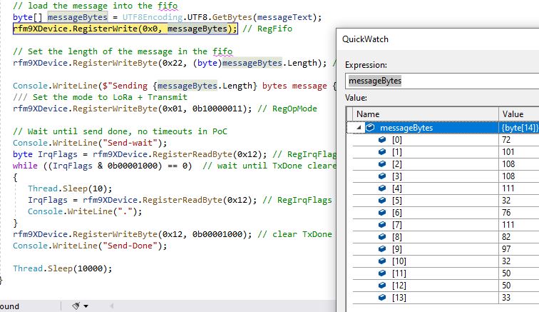
// load the message into the fifo
byte[] messageBytes = UTF8Encoding.UTF8.GetBytes(messageText);
rfm9XDevice.RegisterWrite(0x0, messageBytes); // RegFifo
// Set the length of the message in the fifo
rfm9XDevice.RegisterWriteByte(0x22, (byte)messageBytes.Length); // RegPayloadLength
Console.WriteLine($"Sending {messageBytes.Length} bytes message {messageText}");
/// Set the mode to LoRa + Transmit
rfm9XDevice.RegisterWriteByte(0x01, 0b10000011); // RegOpMode
// Wait until send done, no timeouts in PoC
Console.WriteLine("Send-wait");
byte IrqFlags = rfm9XDevice.RegisterReadByte(0x12); // RegIrqFlags
while ((IrqFlags & 0b00001000) == 0) // wait until TxDone cleared
{
Thread.Sleep(10);
IrqFlags = rfm9XDevice.RegisterReadByte(0x12); // RegIrqFlags
Console.WriteLine(".");
}
Console.WriteLine("");
rfm9XDevice.RegisterWriteByte(0x12, 0b00001000); // clear TxDone bit
Console.WriteLine("Send-Done");
Thread.Sleep(10000);
}
}
catch (Exception ex)
{
Console.WriteLine(ex.Message);
}
}
#if ST_STM32F429I_DISCOVERY
static int PinNumber(char port, byte pin)
{
if (port < 'A' || port > 'J')
throw new ArgumentException();
return ((port - 'A') * 16) + pin;
}
#endif
}
}
When I initially ran the application in Visual Studio 2019 the text below was displayed in the output window.
Register dump
Register 0x00 - Value 0X00
Register 0x01 - Value 0X80
Register 0x02 - Value 0X1A
Register 0x03 - Value 0X0B
Register 0x04 - Value 0X00
…
Register 0x3E - Value 0X00
Register 0x3F - Value 0X00
Register 0x40 - Value 0X00
Register 0x41 - Value 0X00
Register 0x42 - Value 0X12
Sending 13 bytes message Hello LoRa 1!
Send-wait
.
.
.
.
.
Send-Done
Sending 13 bytes message Hello LoRa 2!
Send-wait
.
.
.
.
.
Send-Done
I could the see the messages arriving at the Armtronix device in the Arduino monitor.
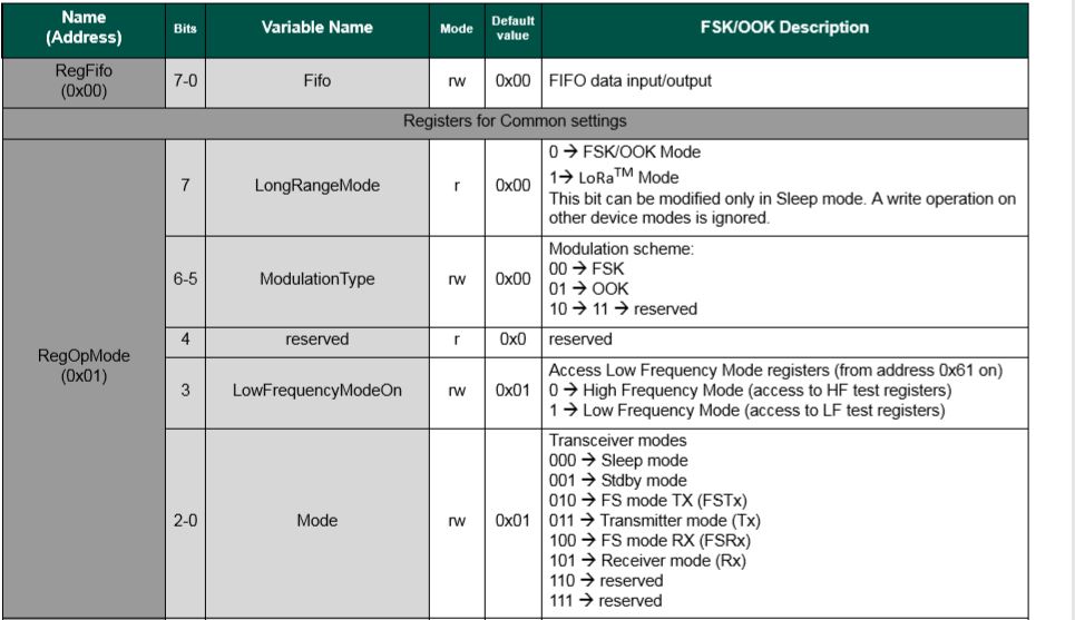
The first message was getting corrupted (only when running in the debugger) which after some trial and error I think was most probably due to my RegOpMode register mode configuration.
SX127X RegOpMode details
// Put device into LoRa + Sleep mode
rfm9XDevice.RegisterWriteByte(0x01, 0b10000000);

// Put device into LoRa + Standby mode
rfm9XDevice.RegisterWriteByte(0x01, 0b10000001);
After a couple of years and half a dozen platform ports still finding bugs in my samples…
STM32F429 Discovery+ Dragino LoRa shield with Armtronix device
/*
  LoRa Duplex communication with Sync Word

  Sends a message every half second, and polls continually
  for new incoming messages. Sets the LoRa radio's Sync Word.

  Spreading factor is basically the radio's network ID. Radios with different
  Sync Words will not receive each other's transmissions. This is one way you
  can filter out radios you want to ignore, without making an addressing scheme.

  See the Semtech datasheet, http://www.semtech.com/images/datasheet/sx1276.pdf
  for more on Sync Word.

  created 28 April 2017
  by Tom Igoe
*/
#include <stdlib.h>
#include <LoRa.h>
const int csPin = PA4;          // LoRa radio chip select
const int resetPin = PC13;       // LoRa radio reset
const int irqPin = PA11;         // change for your board; must be a hardware interrupt pin

byte msgCount = 0;            // count of outgoing messages
int interval = 2000;          // interval between sends
long lastSendTime = 0;        // time of last packet send

void setup() {
  Serial.begin(9600);                   // initialize serial
  while (!Serial);

  Serial.println("LoRa Duplex - Set sync word");

  // override the default CS, reset, and IRQ pins (optional)
  LoRa.setPins(csPin, resetPin, irqPin);// set CS, reset, IRQ pin

  if (!LoRa.begin(915E6)) {             // initialize ratio at 915 MHz
    Serial.println("LoRa init failed. Check your connections.");
    while (true);                       // if failed, do nothing
  }

  LoRa.setSyncWord(0x12);           // ranges from 0-0xFF, default 0x34, see API docs

  LoRa.dumpRegisters(Serial);
  Serial.println("LoRa init succeeded.");
}

void loop() {
  if (millis() - lastSendTime > interval) {
    String message = "HeLoRa World! ";   // send a message
    message += msgCount;
    sendMessage(message);
    Serial.println("Sending " + message);
    lastSendTime = millis();            // timestamp the message
    interval = random(1000) + 10000;    // 10-11 seconds
    msgCount++;
  }

  // parse for a packet, and call onReceive with the result:
  onReceive(LoRa.parsePacket());
}

void sendMessage(String outgoing) {
  LoRa.beginPacket();                   // start packet
  LoRa.print(outgoing);                 // add payload
  LoRa.endPacket();                     // finish packet and send it
  msgCount++;                           // increment message ID
}

void onReceive(int packetSize) {
  if (packetSize == 0) return;          // if there's no packet, return

  // read packet header bytes:
  String incoming = "";

  while (LoRa.available()) {
    incoming += (char)LoRa.read();
  }

  Serial.println("Message: " + incoming);
  Serial.println("RSSI: " + String(LoRa.packetRssi()));
  Serial.println("Snr: " + String(LoRa.packetSnr()));
  Serial.println();
}
The STM32F429 Discovery application
namespace devMobile.IoT.Rfm9x.TransmitBasic
{
   using System;
   using System.Text;
   using System.Threading;

   using Windows.Devices.Gpio;
   using Windows.Devices.Spi;

   public sealed class Rfm9XDevice
   {
      private SpiDevice rfm9XLoraModem;
      private GpioPin chipSelectGpioPin;
      private const byte RegisterAddressReadMask = 0X7f;
      private const byte RegisterAddressWriteMask = 0x80;

      public Rfm9XDevice(string spiPort, int chipSelectPin, int resetPin)
      {
         var settings = new SpiConnectionSettings(chipSelectPin)
         {
            ClockFrequency = 500000,
//            DataBitLength = 8,
            Mode = SpiMode.Mode0,// From SemTech docs pg 80 CPOL=0, CPHA=0
            SharingMode = SpiSharingMode.Shared,
         };

         rfm9XLoraModem = SpiDevice.FromId(spiPort, settings);

         GpioController gpioController = GpioController.GetDefault();

         // Chip select pin configuration
         chipSelectGpioPin = gpioController.OpenPin(chipSelectPin);
         chipSelectGpioPin.SetDriveMode(GpioPinDriveMode.Output);

         // Factory reset pin configuration
         GpioPin resetGpioPin = gpioController.OpenPin(resetPin);
         resetGpioPin.SetDriveMode(GpioPinDriveMode.Output);
         resetGpioPin.Write(GpioPinValue.Low);
         Thread.Sleep(10);
         resetGpioPin.Write(GpioPinValue.High);
         Thread.Sleep(10);
      }

      public Byte RegisterReadByte(byte registerAddress)
      {
         byte[] writeBuffer = new byte[] { registerAddress &= RegisterAddressReadMask, 0x0 };
         byte[] readBuffer = new byte[writeBuffer.Length];

         rfm9XLoraModem.TransferFullDuplex(writeBuffer, readBuffer);

         return readBuffer[1];
      }

      public ushort RegisterReadWord(byte address)
      {
         byte[] writeBuffer = new byte[] { address &= RegisterAddressReadMask, 0x0, 0x0 };
         byte[] readBuffer = new byte[writeBuffer.Length];

         rfm9XLoraModem.TransferFullDuplex(writeBuffer, readBuffer);

         return (ushort)(readBuffer[2] + (readBuffer[1] << 8));
      }

      public byte[] RegisterRead(byte address, int length)
      {
         byte[] writeBuffer = new byte[length + 1];
         byte[] readBuffer = new byte[length + 1];
         byte[] repyBuffer = new byte[length];

         writeBuffer[0] = address &= RegisterAddressReadMask;

         rfm9XLoraModem.TransferFullDuplex(writeBuffer, readBuffer);

         Array.Copy(readBuffer, 1, repyBuffer, 0, length);

         return repyBuffer;
      }

      public void RegisterWriteByte(byte address, byte value)
      {
         byte[] writeBuffer = new byte[] { address |= RegisterAddressWriteMask, value };

         rfm9XLoraModem.Write(writeBuffer);
      }

      public void RegisterWriteWord(byte address, ushort value)
      {
         byte[] valueBytes = BitConverter.GetBytes(value);
         byte[] writeBuffer = new byte[] { address |= RegisterAddressWriteMask, valueBytes[0], valueBytes[1] };

         rfm9XLoraModem.Write(writeBuffer);
      }

      public void RegisterWrite(byte address, byte[] bytes)
      {
         byte[] writeBuffer = new byte[1 + bytes.Length];

         Array.Copy(bytes, 0, writeBuffer, 1, bytes.Length);
         writeBuffer[0] = address |= RegisterAddressWriteMask;

         rfm9XLoraModem.Write(writeBuffer);
      }

      public void RegisterDump()
      {
         Console.WriteLine("Register dump");
         for (byte registerIndex = 0; registerIndex <= 0x42; registerIndex++)
         {
            byte registerValue = this.RegisterReadByte(registerIndex);

            Console.WriteLine($"Register 0x{registerIndex:x2} - Value 0X{registerValue:x2}");
         }
      }
   }

   class Program
   {
      static void Main()
      {
         Rfm9XDevice rfm9XDevice = new Rfm9XDevice("SPI5", PinNumber('C', 2), PinNumber('C', 3));
         int SendCount = 0;

         // Put device into LoRa + Sleep mode
         rfm9XDevice.RegisterWriteByte(0x01, 0b10000000); // RegOpMode

         // Set the frequency to 915MHz
         byte[] frequencyWriteBytes = { 0xE4, 0xC0, 0x00 }; // RegFrMsb, RegFrMid, RegFrLsb
         rfm9XDevice.RegisterWrite(0x06, frequencyWriteBytes);

         // More power PA Boost
         rfm9XDevice.RegisterWriteByte(0x09, 0b10000000); // RegPaConfig

         rfm9XDevice.RegisterDump();

         while (true)
         {
            rfm9XDevice.RegisterWriteByte(0x0E, 0x0); // RegFifoTxBaseAddress

            // Set the Register Fifo address pointer
            rfm9XDevice.RegisterWriteByte(0x0D, 0x0); // RegFifoAddrPtr

            string messageText = $"Hello LoRa {SendCount += 1}!";

            // load the message into the fifo
            byte[] messageBytes = UTF8Encoding.UTF8.GetBytes(messageText);
            rfm9XDevice.RegisterWrite(0x0, messageBytes); // RegFifo

            // Set the length of the message in the fifo
            rfm9XDevice.RegisterWriteByte(0x22, (byte)messageBytes.Length); // RegPayloadLength

            Console.WriteLine($"Sending {messageBytes.Length} bytes message {messageText}");
            /// Set the mode to LoRa + Transmit
            rfm9XDevice.RegisterWriteByte(0x01, 0b10000011); // RegOpMode

            // Wait until send done, no timeouts in PoC
            Console.WriteLine("Send-wait");
            byte IrqFlags = rfm9XDevice.RegisterReadByte(0x12); // RegIrqFlags
            while ((IrqFlags & 0b00001000) == 0)  // wait until TxDone cleared
            {
               Thread.Sleep(10);
               IrqFlags = rfm9XDevice.RegisterReadByte(0x12); // RegIrqFlags
               Console.WriteLine(".");
            }
            rfm9XDevice.RegisterWriteByte(0x12, 0b00001000); // clear TxDone bit
            Console.WriteLine("Send-Done");

            Thread.Sleep(10000);
         }
      }

      static int PinNumber(char port, byte pin)
      {
         if (port < 'A' || port > 'J')
            throw new ArgumentException();

         return ((port - 'A') * 16) + pin;
      }
   }
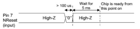
Now that I could reliably dump all the Dragino shield registers I wanted to be able to configure the Semtech 127X device and reset it back to factory settings. A factory reset is done by strobing the reset pin on the device.
SX127X Reset process
To support this my Rfm9XDevice class constructor gained an additional parameter the reset GPIO pin number(my test harness also gained a jumper wire, the blue one). The PinNumber helper is more user friendly that the raw numbers and is “inspired” by sample nanoFramework code
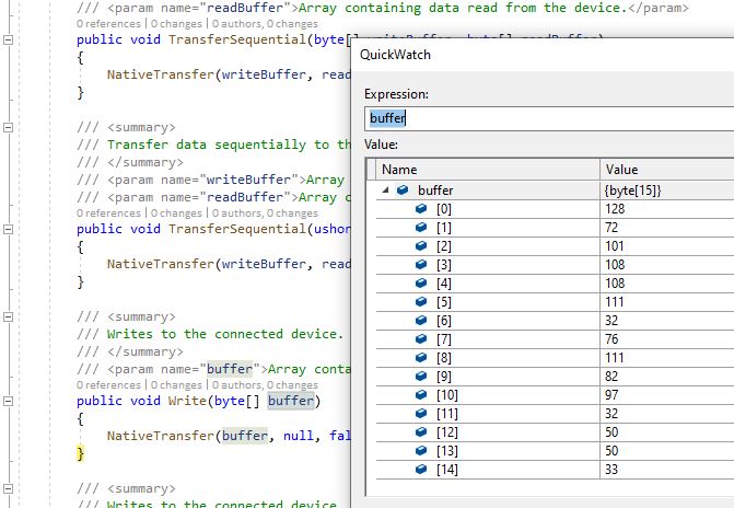
To configure the RFM9X I wrote some wrapper functions for the nanoFramwork SPIAPI to read/write byte values, word values and arrays of bytes.
SCK->PF7->D10
MISO->PF8->D12
MOSI->PF9->D11
CS->PC2->D10
Reset->PC1->D9
Each method was tested by read/writing suitable register(s) in the device configuration (Needed to set it into LoRa mode first).
namespace devMobile.IoT.Rfm9x.RegisterReadAndWrite
{
   using System;
   using System.Threading;

   using Windows.Devices.Gpio;
   using Windows.Devices.Spi;

   public sealed class Rfm9XDevice
   {
      private SpiDevice rfm9XLoraModem;
      private const byte RegisterAddressReadMask = 0X7f;
      private const byte RegisterAddressWriteMask = 0x80;

      public Rfm9XDevice(string spiPort, int chipSelectPin, int resetPin)
      {
         var settings = new SpiConnectionSettings(chipSelectPin)
         {
            ClockFrequency = 1000000,
            Mode = SpiMode.Mode0,// From SemTech docs pg 80 CPOL=0, CPHA=0
            SharingMode = SpiSharingMode.Shared
         };

         rfm9XLoraModem = SpiDevice.FromId(spiPort, settings);

         // Factory reset pin configuration
         GpioController gpioController = GpioController.GetDefault();
         GpioPin resetGpioPin = gpioController.OpenPin(resetPin);
         resetGpioPin.SetDriveMode(GpioPinDriveMode.Output);
         resetGpioPin.Write(GpioPinValue.Low);
         Thread.Sleep(10);
         resetGpioPin.Write(GpioPinValue.High);
         Thread.Sleep(10);
      }

      public Byte RegisterReadByte(byte registerAddress)
      {
         byte[] writeBuffer = new byte[] { registerAddress &= RegisterAddressReadMask, 0x0 };
         byte[] readBuffer = new byte[writeBuffer.Length];

         rfm9XLoraModem.TransferFullDuplex(writeBuffer, readBuffer);

         return readBuffer[1];
      }

      public ushort RegisterReadWord(byte address)
      {
         byte[] writeBuffer = new byte[] { address &= RegisterAddressReadMask, 0x0, 0x0 };
         byte[] readBuffer = new byte[writeBuffer.Length];

         rfm9XLoraModem.TransferFullDuplex(writeBuffer, readBuffer);

         return (ushort)(readBuffer[2] + (readBuffer[1] << 8));
      }

      public byte[] RegisterRead(byte address, int length)
      {
         byte[] writeBuffer = new byte[length + 1];
         byte[] readBuffer = new byte[length + 1];
         byte[] repyBuffer = new byte[length];

         writeBuffer[0] = address &= RegisterAddressReadMask;

         rfm9XLoraModem.TransferFullDuplex(writeBuffer, readBuffer);

         Array.Copy(readBuffer, 1, repyBuffer, 0, length);

         return repyBuffer;
      }

      public void RegisterWriteByte(byte address, byte value)
      {
         byte[] writeBuffer = new byte[] { address |= RegisterAddressWriteMask, value };

         rfm9XLoraModem.Write(writeBuffer);
      }

      public void RegisterWriteWord(byte address, ushort value)
      {
         byte[] valueBytes = BitConverter.GetBytes(value);
         byte[] writeBuffer = new byte[] { address |= RegisterAddressWriteMask, valueBytes[0], valueBytes[1] };

         rfm9XLoraModem.Write(writeBuffer);
      }

      public void RegisterWrite(byte address, byte[] bytes)
      {
         byte[] writeBuffer = new byte[1 + bytes.Length];

         Array.Copy(bytes, 0, writeBuffer, 1, bytes.Length);
         writeBuffer[0] = address |= RegisterAddressWriteMask;

         rfm9XLoraModem.Write(writeBuffer);
      }

      public void RegisterDump()
      {
         Console.WriteLine("Register dump");
         for (byte registerIndex = 0; registerIndex <= 0x42; registerIndex++)
         {
            byte registerValue = this.RegisterReadByte(registerIndex);

            Console.WriteLine($"Register 0x{registerIndex:x2} - Value 0X{registerValue:x2}");
         }
      }
   }

   class Program
   {
      static void Main()
      {
         Rfm9XDevice rfm9XDevice = new Rfm9XDevice("SPI5", PinNumber('C', 2), PinNumber('C', 3));

         rfm9XDevice.RegisterDump();

         while (true)
         {
            Console.WriteLine("Read RegOpMode (read byte)");
            Byte regOpMode1 = rfm9XDevice.RegisterReadByte(0x1);
            Console.WriteLine($"RegOpMode 0x{regOpMode1:x2}");

            Console.WriteLine("Set LoRa mode and sleep mode (write byte)");
            rfm9XDevice.RegisterWriteByte(0x01, 0b10000000);

            Console.WriteLine("Read RegOpMode (read byte)");
            Byte regOpMode2 = rfm9XDevice.RegisterReadByte(0x1);
            Console.WriteLine($"RegOpMode 0x{regOpMode2:x2}");

            Console.WriteLine("Read the preamble (read word)");
            ushort preamble = rfm9XDevice.RegisterReadWord(0x20);
            Console.WriteLine($"Preamble 0x{preamble:x2}");

            Console.WriteLine("Set the preamble to 0x80 (write word)");
            rfm9XDevice.RegisterWriteWord(0x20, 0x80);

            Console.WriteLine("Read the center frequency (read byte array)");
            byte[] frequencyReadBytes = rfm9XDevice.RegisterRead(0x06, 5);
            Console.WriteLine($"Frequency Msb 0x{frequencyReadBytes[0]:x2} Mid 0x{frequencyReadBytes[1]:x2} Lsb 0x{frequencyReadBytes[2]:x2}");

            Console.WriteLine("Set the center frequency to 916MHz (write byte array)");
            byte[] frequencyWriteBytes = { 0xE4, 0xC0, 0x00 };
            rfm9XDevice.RegisterWrite(0x06, frequencyWriteBytes);

            rfm9XDevice.RegisterDump();

            Thread.Sleep(30000);
         }
      }

      static int PinNumber(char port, byte pin)
      {
         if (port < 'A' || port > 'J')
            throw new ArgumentException();

         return ((port - 'A') * 16) + pin;
      }
   }
The output of the application looked like this
Attaching to nanoDevice...
Waiting for nanoDevice to initialize...
Updating nanoDevice debugger engine.
The nanoDevice runtime is loading the application assemblies and starting execution.
'nanoFramework.Tools.VS2019.Extension.dll' (Managed): Loaded 'C:\Users\BrynLewis\source\repos\RFM9X.NetNF\RegisterReadAndWrite\bin\Debug\RegisterReadAndWrite.exe', Symbols loaded.
'nanoFramework.Tools.VS2019.Extension.dll' (Managed): Loaded 'C:\Users\BrynLewis\source\repos\RFM9X.NetNF\packages\nanoFramework.Windows.Devices.Spi.1.3.0-preview.12\lib\Windows.Devices.Spi.dll', Symbols loaded.
'nanoFramework.Tools.VS2019.Extension.dll' (Managed): Loaded 'C:\Users\BrynLewis\source\repos\RFM9X.NetNF\packages\nanoFramework.Runtime.Events.1.4.2-preview.1\lib\nanoFramework.Runtime.Events.dll', Symbols loaded.
'nanoFramework.Tools.VS2019.Extension.dll' (Managed): Loaded 'C:\Users\BrynLewis\source\repos\RFM9X.NetNF\packages\nanoFramework.Windows.Devices.Gpio.1.4.1-preview.13\lib\Windows.Devices.Gpio.dll', Symbols loaded.
The thread '<No Name>' (0x2) has exited with code 0 (0x0).
Register dump
Register 0x00 - Value 0X00
Register 0x01 - Value 0X09
Register 0x02 - Value 0X1A
Register 0x03 - Value 0X0B
Register 0x04 - Value 0X00
Register 0x05 - Value 0X52
Register 0x06 - Value 0X6C
Register 0x07 - Value 0X80
Register 0x08 - Value 0X00
Register 0x09 - Value 0X4F
Register 0x0A - Value 0X09
Register 0x0B - Value 0X2B
Register 0x0C - Value 0X20
Register 0x0D - Value 0X08
Register 0x0E - Value 0X02
Register 0x0F - Value 0X0A
Register 0x10 - Value 0XFF
Register 0x11 - Value 0X70
Register 0x12 - Value 0X15
Register 0x13 - Value 0X0B
Register 0x14 - Value 0X28
Register 0x15 - Value 0X0C
Register 0x16 - Value 0X12
Register 0x17 - Value 0X47
Register 0x18 - Value 0X32
Register 0x19 - Value 0X3E
Register 0x1A - Value 0X00
Register 0x1B - Value 0X00
Register 0x1C - Value 0X00
Register 0x1D - Value 0X00
Register 0x1E - Value 0X00
Register 0x1F - Value 0X40
Register 0x20 - Value 0X00
Register 0x21 - Value 0X00
Register 0x22 - Value 0X00
Register 0x23 - Value 0X00
Register 0x24 - Value 0X05
Register 0x25 - Value 0X00
Register 0x26 - Value 0X03
Register 0x27 - Value 0X93
Register 0x28 - Value 0X55
Register 0x29 - Value 0X55
Register 0x2A - Value 0X55
Register 0x2B - Value 0X55
Register 0x2C - Value 0X55
Register 0x2D - Value 0X55
Register 0x2E - Value 0X55
Register 0x2F - Value 0X55
Register 0x30 - Value 0X90
Register 0x31 - Value 0X40
Register 0x32 - Value 0X40
Register 0x33 - Value 0X00
Register 0x34 - Value 0X00
Register 0x35 - Value 0X0F
Register 0x36 - Value 0X00
Register 0x37 - Value 0X00
Register 0x38 - Value 0X00
Register 0x39 - Value 0XF5
Register 0x3A - Value 0X20
Register 0x3B - Value 0X82
Register 0x3C - Value 0XF8
Register 0x3D - Value 0X02
Register 0x3E - Value 0X80
Register 0x3F - Value 0X40
Register 0x40 - Value 0X00
Register 0x41 - Value 0X00
Register 0x42 - Value 0X12
Read RegOpMode (read byte)
RegOpMode 0x09
Set LoRa mode and sleep mode (write byte)
Read RegOpMode (read byte)
RegOpMode 0x80
Read the preamble (read word)
Preamble 0x08
Set the preamble to 0x80 (write word)
Read the center frequency (read byte array)
Frequency Msb 0x6C Mid 0x80 Lsb 0x00
Set the center frequency to 916MHz (write byte array)
Register dump
Register 0x00 - Value 0X8F
Register 0x01 - Value 0X80
Register 0x02 - Value 0XFF
Register 0x03 - Value 0XFF
Register 0x04 - Value 0X00
Register 0x05 - Value 0X52
Register 0x06 - Value 0XE4
Register 0x07 - Value 0XC0
Register 0x08 - Value 0X00
Register 0x09 - Value 0XFF
Register 0x0A - Value 0X7F
Register 0x0B - Value 0X3F
Register 0x0C - Value 0X3F
Register 0x0D - Value 0X00
Register 0x0E - Value 0XFF
Register 0x0F - Value 0X00
Register 0x10 - Value 0X00
Register 0x11 - Value 0X00
Register 0x12 - Value 0X00
Register 0x13 - Value 0X00
Register 0x14 - Value 0X00
Register 0x15 - Value 0X00
Register 0x16 - Value 0X00
Register 0x17 - Value 0X00
Register 0x18 - Value 0X10
Register 0x19 - Value 0X00
Register 0x1A - Value 0X00
Register 0x1B - Value 0X00
Register 0x1C - Value 0X00
Register 0x1D - Value 0X72
Register 0x1E - Value 0X70
Register 0x1F - Value 0X64
Register 0x20 - Value 0X80
Register 0x21 - Value 0X00
Register 0x22 - Value 0XFF
Register 0x23 - Value 0XFF
Register 0x24 - Value 0XFF
Register 0x25 - Value 0X00
Register 0x26 - Value 0X04
Register 0x27 - Value 0X00
Register 0x28 - Value 0X00
Register 0x29 - Value 0X00
Register 0x2A - Value 0X00
Register 0x2B - Value 0X00
Register 0x2C - Value 0X00
Register 0x2D - Value 0X50
Register 0x2E - Value 0X14
Register 0x2F - Value 0X45
Register 0x30 - Value 0X55
Register 0x31 - Value 0XC3
Register 0x32 - Value 0X05
Register 0x33 - Value 0X27
Register 0x34 - Value 0X1C
Register 0x35 - Value 0X0A
Register 0x36 - Value 0X03
Register 0x37 - Value 0X0A
Register 0x38 - Value 0X42
Register 0x39 - Value 0X12
Register 0x3A - Value 0X49
Register 0x3B - Value 0X1D
Register 0x3C - Value 0X00
Register 0x3D - Value 0XAF
Register 0x3E - Value 0X00
Register 0x3F - Value 0X00
Register 0x40 - Value 0X00
Register 0x41 - Value 0X00
Register 0x42 - Value 0X12
The next step is to extract the SPI register access functionality into a module and configure the bare minimum of settings required to get the SX127X to transmit.
First step was to confirm I could (using the nanoFramework GPIO and SPI Nuget packages) read a couple of the Semtech SX1276 registers.
//---------------------------------------------------------------------------------
// Copyright (c) April 2020, devMobile Software
//
// Licensed under the Apache License, Version 2.0 (the "License");
// you may not use this file except in compliance with the License.
// You may obtain a copy of the License at
//
//     http://www.apache.org/licenses/LICENSE-2.0
//
// Unless required by applicable law or agreed to in writing, software
// distributed under the License is distributed on an "AS IS" BASIS,
// WITHOUT WARRANTIES OR CONDITIONS OF ANY KIND, either express or implied.
// See the License for the specific language governing permissions and
// limitations under the License.
//
//---------------------------------------------------------------------------------
namespace devMobile.IoT.Rfm9x.ShieldSPI
{
   using System;
   using System.Threading;

   using Windows.Devices.Gpio;
   using Windows.Devices.Spi;

   public class Program
   {
      public static void Main()
      {
         try
         {
            GpioController gpioController = GpioController.GetDefault();

            GpioPin chipSelectGpioPin = gpioController.OpenPin(PinNumber('C', 2));
            chipSelectGpioPin.SetDriveMode(GpioPinDriveMode.Output);

            var settings = new SpiConnectionSettings(chipSelectGpioPin.PinNumber)
            {
               ClockFrequency = 500000,
               Mode = SpiMode.Mode0,// From SemTech docs pg 80 CPOL=0, CPHA=0
               //Mode = SpiMode.Mode1,
               //Mode = SpiMode.Mode2,
               //Mode = SpiMode.Mode3,
               SharingMode = SpiSharingMode.Shared,
               //SharingMode = SpiSharingMode.Exclusive,
            };


            SpiDevice Device = SpiDevice.FromId("SPI5", settings);

            Thread.Sleep(500);

            while (true)
            {
               byte[] writeBuffer = new byte[] { 0x42 };
               byte[] readBuffer = new byte[1];

               //Device.Write(writeBuffer);
               //Device.Read(readBuffer);
               Device.TransferSequential(writeBuffer, readBuffer);

               byte registerValue = readBuffer[0];
               Console.WriteLine(String.Format("Register 0x{0:x2} - Value 0X{1:x2}", 0x42, registerValue));

               Thread.Sleep(10000);
            }
         }
         catch (Exception ex)
         {
            Console.WriteLine(ex.Message);
         }
      }

      static int PinNumber(char port, byte pin)
      {
         if (port < 'A' || port > 'J')
            throw new ArgumentException();

         return ((port - 'A') * 16) + pin;
      }
   }
}
After trying many permutations of settings I could successfully read the RegVersion and default frequency values
Attaching to nanoDevice...
Waiting for nanoDevice to initialize...
Updating nanoDevice debugger engine.
The nanoDevice runtime is loading the application assemblies and starting execution.
'nanoFramework.Tools.VS2019.Extension.dll' (Managed): Loaded 'C:\Users\BrynLewis\source\repos\RFM9X.NetNF\ShieldSPI\bin\Debug\ShieldSPI.exe', Symbols loaded.
'nanoFramework.Tools.VS2019.Extension.dll' (Managed): Loaded 'C:\Users\BrynLewis\source\repos\RFM9X.NetNF\packages\nanoFramework.Windows.Devices.Spi.1.3.0-preview.12\lib\Windows.Devices.Spi.dll', Symbols loaded.
'nanoFramework.Tools.VS2019.Extension.dll' (Managed): Loaded 'C:\Users\BrynLewis\source\repos\RFM9X.NetNF\packages\nanoFramework.Runtime.Events.1.4.2-preview.1\lib\nanoFramework.Runtime.Events.dll', Symbols loaded.
'nanoFramework.Tools.VS2019.Extension.dll' (Managed): Loaded 'C:\Users\BrynLewis\source\repos\RFM9X.NetNF\packages\nanoFramework.Windows.Devices.Gpio.1.4.1-preview.13\lib\Windows.Devices.Gpio.dll', Symbols loaded.
The thread '<No Name>' (0x2) has exited with code 0 (0x0).
Register 0x42 - Value 0X12
Register 0x42 - Value 0X12
Mapping the Discovery board pins to corresponding SPI and GPIO pins was a bit painful