RFM69 hat library Part5

Receive Basic: Rasmatic/RFM69-Arduino-Library

Next step was to extend my code to receive packets (no addressing or encryption). Initially I didn’t receive any messages as I had neglected to configure the variable length flag (RegPacketConfig bit 7) and had a typo in the RegRxBw register configuration.

/*
 Copyright ® 2019 June devMobile Software, All Rights Reserved

 MIT License

 Permission is hereby granted, free of charge, to any person obtaining a copy
 of this software and associated documentation files (the "Software"), to deal
 in the Software without restriction, including without limitation the rights
 to use, copy, modify, merge, publish, distribute, sublicense, and/or sell
 copies of the Software, and to permit persons to whom the Software is
 furnished to do so, subject to the following conditions:

 The above copyright notice and this permission notice shall be included in all
 copies or substantial portions of the Software.

 THE SOFTWARE IS PROVIDED "AS IS", WITHOUT WARRANTY OF ANY KIND, EXPRESS OR
 IMPLIED, INCLUDING BUT NOT LIMITED TO THE WARRANTIES OF MERCHANTABILITY,
 FITNESS FOR A PARTICULAR PURPOSE AND NONINFRINGEMENT. IN NO EVENT SHALL THE
 AUTHORS OR COPYRIGHT HOLDERS BE LIABLE FOR ANY CLAIM, DAMAGES OR OTHER
 LIABILITY, WHETHER IN AN ACTION OF CONTRACT, TORT OR OTHERWISE, ARISING FROM,
 OUT OF OR IN CONNECTION WITH THE SOFTWARE OR THE USE OR OTHER DEALINGS IN THE
 SOFTWARE

*/
namespace devMobile.IoT.Rfm69Hcw.ReceiveBasic
{
	using System;
	using System.Diagnostics;
	using System.Runtime.InteropServices.WindowsRuntime;
	using System.Text;
	using System.Threading.Tasks;
	using Windows.ApplicationModel.Background;
	using Windows.Devices.Spi;
	using Windows.Devices.Gpio;

	public sealed class Rfm69HcwDevice
	{
		private SpiDevice Rfm69Hcw;
		private const byte RegisterAddressReadMask = 0X7f;
		private const byte RegisterAddressWriteMask = 0x80;

		public Rfm69HcwDevice(int chipSelectPin, int resetPin)
		{
			SpiController spiController = SpiController.GetDefaultAsync().AsTask().GetAwaiter().GetResult();
			var settings = new SpiConnectionSettings(chipSelectPin)
			{
				ClockFrequency = 500000,
				Mode = SpiMode.Mode0,
			};

			// Factory reset pin configuration
			GpioController gpioController = GpioController.GetDefault();
			GpioPin resetGpioPin = gpioController.OpenPin(resetPin);
			resetGpioPin.SetDriveMode(GpioPinDriveMode.Output);
			resetGpioPin.Write(GpioPinValue.Low);
			Task.Delay(100);
			resetGpioPin.Write(GpioPinValue.High);
			Task.Delay(100);
			resetGpioPin.Write(GpioPinValue.Low);

			Task.Delay(100);

			Rfm69Hcw = spiController.GetDevice(settings);
		}

		public Byte RegisterReadByte(byte address)
		{
			byte[] writeBuffer = new byte[] { address &= RegisterAddressReadMask };
			byte[] readBuffer = new byte[1];
			Debug.Assert(Rfm69Hcw != null);

			Rfm69Hcw.TransferSequential(writeBuffer, readBuffer);

			return readBuffer[0];
		}

		public ushort RegisterReadWord(byte address)
		{
			byte[] writeBuffer = new byte[] { address &= RegisterAddressReadMask };
			byte[] readBuffer = new byte[2];
			Debug.Assert(Rfm69Hcw != null);

			Rfm69Hcw.TransferSequential(writeBuffer, readBuffer);

			return (ushort)(readBuffer[1] + (readBuffer[0] << 8));
		}

		public byte[] RegisterRead(byte address, int length)
		{
			byte[] writeBuffer = new byte[] { address &= RegisterAddressReadMask };
			byte[] readBuffer = new byte[length];
			Debug.Assert(Rfm69Hcw != null);

			Rfm69Hcw.TransferSequential(writeBuffer, readBuffer);

			return readBuffer;
		}

		public void RegisterWriteByte(byte address, byte value)
		{
			byte[] writeBuffer = new byte[] { address |= RegisterAddressWriteMask, value };
			Debug.Assert(Rfm69Hcw != null);

			Rfm69Hcw.Write(writeBuffer);
		}

		public void RegisterWriteWord(byte address, ushort value)
		{
			byte[] valueBytes = BitConverter.GetBytes(value);
			byte[] writeBuffer = new byte[] { address |= RegisterAddressWriteMask, valueBytes[0], valueBytes[1] };
			Debug.Assert(Rfm69Hcw != null);

			Rfm69Hcw.Write(writeBuffer);
		}

		public void RegisterWrite(byte address, [ReadOnlyArray()] byte[] bytes)
		{
			byte[] writeBuffer = new byte[1 + bytes.Length];
			Debug.Assert(Rfm69Hcw != null);

			Array.Copy(bytes, 0, writeBuffer, 1, bytes.Length);
			writeBuffer[0] = address |= RegisterAddressWriteMask;

			Rfm69Hcw.Write(writeBuffer);
		}

		public void RegisterDump()
		{
			Debug.WriteLine("Register dump");
			for (byte registerIndex = 0; registerIndex <= 0x3D; registerIndex++)
			{
				byte registerValue = this.RegisterReadByte(registerIndex);

				Debug.WriteLine("Register 0x{0:x2} - Value 0X{1:x2} - Bits {2}", registerIndex, registerValue, Convert.ToString(registerValue, 2).PadLeft(8, '0'));
			}
		}
	}


	public sealed class StartupTask : IBackgroundTask
	{
		private const int ChipSelectLine = 1;
		private const int ResetLine = 25;
		private Rfm69HcwDevice rfm69Device = new Rfm69HcwDevice(ChipSelectLine, ResetLine);

		const double RH_RF6M9HCW_FXOSC = 32000000.0;
		const double RH_RFM69HCW_FSTEP = RH_RF6M9HCW_FXOSC / 524288.0;

		public void Run(IBackgroundTaskInstance taskInstance)
		{
			//rfm69Device.RegisterDump();

			// regOpMode standby
			rfm69Device.RegisterWriteByte(0x01, 0b00000100);

			// BitRate MSB/LSB
			rfm69Device.RegisterWriteByte(0x03, 0x34);
			rfm69Device.RegisterWriteByte(0x04, 0x00);

			// Calculate the frequency accoring to the datasheett
			byte[] bytes = BitConverter.GetBytes((uint)(915000000.0 / RH_RFM69HCW_FSTEP));
			Debug.WriteLine("Byte Hex 0x{0:x2} 0x{1:x2} 0x{2:x2} 0x{3:x2}", bytes[0], bytes[1], bytes[2], bytes[3]);
			rfm69Device.RegisterWriteByte(0x07, bytes[2]);
			rfm69Device.RegisterWriteByte(0x08, bytes[1]);
			rfm69Device.RegisterWriteByte(0x09, bytes[0]);

			// RegRxBW
			rfm69Device.RegisterWriteByte(0x19, 0x2a);

			// Setup preamble length to 16 (default is 3) RegPreambleMsb RegPreambleLsb
			rfm69Device.RegisterWriteByte(0x2C, 0x0);
			rfm69Device.RegisterWriteByte(0x2D, 0x10);

			// RegSyncConfig Set the Sync length and byte values SyncOn + 3 custom sync bytes
			rfm69Device.RegisterWriteByte(0x2e, 0x90);

			// RegSyncValues1 thru RegSyncValues3
			rfm69Device.RegisterWriteByte(0x2f, 0xAA);
			rfm69Device.RegisterWriteByte(0x30, 0x2D);
			rfm69Device.RegisterWriteByte(0x31, 0xD4);

			// RegPacketConfig1 Variable length with CRC on
			rfm69Device.RegisterWriteByte(0x37, 0x90);

			rfm69Device.RegisterWriteByte(0x01, 0b00010000); // RegOpMode set ReceiveMode

			rfm69Device.RegisterDump();

			while (true)
			{
				// Wait until a packet is received, no timeouts in PoC
				Debug.WriteLine("Receive-Wait");
				byte IrqFlags = rfm69Device.RegisterReadByte(0x28); // RegIrqFlags2
				while ((IrqFlags & 0b00000100) == 0)  // wait until PayLoadReady set
				{
					Task.Delay(20).Wait();
					IrqFlags = rfm69Device.RegisterReadByte(0x28); // RegIrqFlags2
					//Debug.WriteLine(string.Format("RegIrqFlags {0}", Convert.ToString((byte)IrqFlags, 2).PadLeft(8, '0')));
					Debug.Write(".");
				}
				Debug.WriteLine("");

				// Rwad the length
				byte numberOfBytes = rfm69Device.RegisterReadByte(0x0); 

				// Allocate buffer for message
				byte[] messageBytes = new byte[numberOfBytes];

				for (int i = 0; i < numberOfBytes; i++)
				{
					messageBytes[i] = rfm69Device.RegisterReadByte(0x00); // RegFifo
				}

				string messageText = UTF8Encoding.UTF8.GetString(messageBytes);
				Debug.WriteLine("Received {0} byte message {1}", messageBytes.Length, messageText);

				Debug.WriteLine("Receive-Done");
			}
		}
	}
}

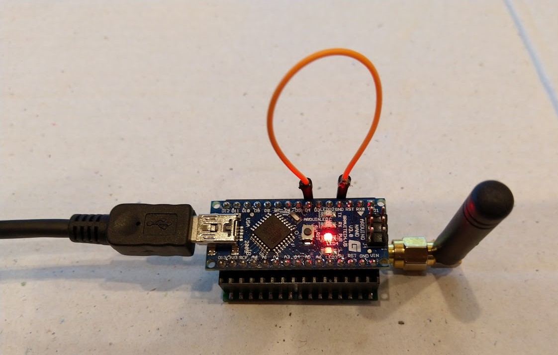
I modified the Arduino application to transmit a message (with a counter so I could spot dropped messages) every second

#include <SPI.h>
#include <stdio.h>
#include <RMRFM69.h>

#define SENDER_DETECT_PIN 4

RMRFM69 radio(SPI, 10, 2, 9);

byte counter = 0 ;

void setup() 
{
  Serial.begin(9600);

  pinMode(SENDER_DETECT_PIN, INPUT_PULLUP);  
  
  radio.Modulation     = FSK;
  radio.COB            = RFM69;
  radio.Frequency      = 915000;
  radio.OutputPower    = 10+18;          //10dBm OutputPower
  radio.PreambleLength = 16;             //16Byte preamble
  radio.FixedPktLength = false;          //packet in message which need to be send
  radio.CrcDisable     = false;          //CRC On
  radio.AesOn          = false;
  radio.SymbolTime     = 416000;         //2.4Kbps
  radio.Devation       = 35;             //35KHz for devation
  radio.BandWidth      = 100;            //100KHz for bandwidth
  radio.SyncLength     = 3;              //
  radio.SyncWord[0]    = 0xAA;
  radio.SyncWord[1]    = 0x2D;
  radio.SyncWord[2]    = 0xD4;

  radio.vInitialize();
  
  if (digitalRead(SENDER_DETECT_PIN) == LOW)
  {
    Serial.println("RX start");
    radio.vGoRx();
  }
  else
  {
    Serial.println("TX start");
    //radio.vGoTx();    
  }
  radio.dumpRegisters(Serial);
}

void loop() 
{
  char messageIn[128] = {""};
  char messageOut[32]= {"Hello world:"};

  if (digitalRead(SENDER_DETECT_PIN) == LOW)
  {
    if(radio.bGetMessage(messageIn)!=0)
    { 
      Serial.print("MessageIn:");
      Serial.println(messageIn);
    }    
  }
  else
  {  
    Serial.print("MessageOut:") ;
    itoa(counter,&messageOut[strlen( messageOut)],10);
    Serial.println(messageOut);
    if (!radio.bSendMessage(messageOut, strlen(messageOut)))
    {
      Serial.println("bSendMessage failed");
    }
    counter++;
    delay(1000);
  }
}
Arduino device in receive mode

With the Arduino device transmitting the debug output in Visual Studio looked like this. It does seem a bit odd that the “Receive-Wait” is slowly getting longer.

Register dump
Register 0x00 - Value 0X00 - Bits 00000000
Register 0x01 - Value 0X10 - Bits 00010000
…
Register 0x3c - Value 0X0f - Bits 00001111
Register 0x3d - Value 0X02 - Bits 00000010
Receive-Wait
The thread 0x990 has exited with code 0 (0x0).
Received 13 byte message Hello world:0
Receive-Done
Receive-Wait
.............................................
Received 13 byte message Hello world:1
Receive-Done
Receive-Wait
...........................................
Received 13 byte message Hello world:2
Receive-Done
Receive-Wait
............................................
Received 13 byte message Hello world:3
Receive-Done
Receive-Wait
............................................
Received 13 byte message Hello world:4
Receive-Done
Receive-Wait
.............................................
Received 13 byte message Hello world:5
Receive-Done
Receive-Wait
............................................
Received 13 byte message Hello world:6
Receive-Done
Receive-Wait
............................................

I ran the client for several hours and it didn’t appear to drop any messages. Next step is to covert the receive and transmit code to use interrupts.

RFM69 hat library Part4B

Transmit Basic: iwanders/plainRFM69

My first Arduino client was based on the plainRFM69 library which looks fairly lightweight (it has in memory message queues). I started by adapting the plainRFM69 “Minimal” sample.

/*
 *  Copyright (c) 2014, Ivor Wanders
 *  MIT License, see the LICENSE.md file in the root folder.
*/
#include <SPI.h>
#include <plainRFM69.h>

// slave select pin.
#define SLAVE_SELECT_PIN 10     

// connected to the reset pin of the RFM69.
#define RESET_PIN 9

// tie this pin down on the receiver.
#define SENDER_DETECT_PIN 4

/*
    This is very minimal, it does not use the interrupt.

    Using the interrupt is recommended.
*/

plainRFM69 rfm = plainRFM69(SLAVE_SELECT_PIN);

void sender(){

    uint32_t start_time = millis();

    uint32_t counter = 0; // the counter which we are going to send.

    while(true){
        rfm.poll(); // run poll as often as possible.

        if (!rfm.canSend()){
            continue; // sending is not possible, already sending.
        }
        if ((millis() - start_time) > 500){ // every 500 ms. 
            start_time = millis();

            // be a little bit verbose.
            Serial.print("Send:");Serial.println(counter);

//            rfm.dumpRegisters(Serial);

            // send the number of bytes equal to that set with setPacketLength.
            // read those bytes from memory where counter starts.
            rfm.send(&counter);
            
            counter++; // increase the counter.
        }
    }
}

void receiver(){
    uint32_t counter = 0; // to count the messages.

    while(true){

        rfm.poll(); // poll as often as possible.

        while(rfm.available()){ // for all available messages:

            uint32_t received_count = 0; // temporary for the new counter.
            uint8_t len = rfm.read(&received_count); // read the packet into the new_counter.

            // print verbose output.
            Serial.print("Packet ("); Serial.print(len); Serial.print("): "); Serial.println(received_count);

            if (counter+1 != received_count){
                // if the increment is larger than one, we lost one or more packets.
                Serial.println("Packetloss detected!");
            }

            // assign the received counter to our counter.
            counter = received_count;
        }
    }
}

void setup(){
    Serial.begin(9600);
    SPI.begin();

    bareRFM69::reset(RESET_PIN); // sent the RFM69 a hard-reset.

    rfm.setRecommended(); // set recommended paramters in RFM69.
    rfm.setPacketType(false, false); // set the used packet type.

    rfm.setBufferSize(2);   // set the internal buffer size.
    rfm.setPacketLength(4); // set the packet length.
    rfm.setFrequency((uint32_t) 915*1000*1000); // set the frequency.

    // baudrate is default, 4800 bps now.
    rfm.dumpRegisters(Serial);
    
    rfm.receive();
    // set it to receiving mode.

    pinMode(SENDER_DETECT_PIN, INPUT_PULLUP);
    delay(5);
}

void loop(){
    if (digitalRead(SENDER_DETECT_PIN) == LOW){
        Serial.println("Going Receiver!");
        receiver(); 
        // this function never returns and contains an infinite loop.
    } else {
        Serial.println("Going sender!");
        sender();
        // idem.
    }
}
Arduino RFM69HCW Client in receive mode

I added code to dump the all the Arduino Nano Radio Shield RFM69/95 registers so I could compare it with my Adafruit RFM69HCW Radio Bonnet configuration. I also modified the code to set the three frequency registers so they matched the sample values based on the calculation in the RFM69HCW datasheet. I spent a lot of time manually configuring individual registers on the Adafruit bonnet (ignoring registers like 0x24 RegRssiValue).

void bareRFM69::dumpRegisters(Stream& out)
{
  for (int i = 0; i <= 0x3d; i++) {
    out.print("0x");
    out.print(i, HEX);
    out.print(": 0x");
    out.println(this->readRegister(i), HEX);
  }
}

void plainRFM69::setFrequency(uint32_t freq){
     uint64_t frf = ((uint64_t)freq << 19) / 32000000;
    this->setFrf(frf);
}

After much “trial and error” I found that my Arduino device would only receive messages from my Windows 10 IoT Core device when a third Arduino device was transmitting.

21:10:50.819 -> 0x0: 0x0
21:10:50.819 -> 0x1: 0x4
21:10:50.852 -> 0x2: 0x0
21:10:50.852 -> 0x3: 0x1A
21:10:50.852 -> 0x4: 0xB
21:10:50.886 -> 0x5: 0x0
21:10:50.886 -> 0x6: 0x52
21:10:50.886 -> 0x7: 0xE4
21:10:50.920 -> 0x8: 0xC0
21:10:50.920 -> 0x9: 0x0
21:10:50.920 -> 0xA: 0x41
21:10:50.954 -> 0xB: 0x40
21:10:50.954 -> 0xC: 0x2
21:10:50.954 -> 0xD: 0x92
21:10:50.988 -> 0xE: 0xF5
21:10:50.988 -> 0xF: 0x20
21:10:50.988 -> 0x10: 0x24
21:10:51.022 -> 0x11: 0x9F
21:10:51.022 -> 0x12: 0x9
21:10:51.056 -> 0x13: 0x1A
21:10:51.056 -> 0x14: 0x40
21:10:51.056 -> 0x15: 0xB0
21:10:51.089 -> 0x16: 0x7B
21:10:51.089 -> 0x17: 0x9B
21:10:51.089 -> 0x18: 0x88
21:10:51.124 -> 0x19: 0x55
21:10:51.124 -> 0x1A: 0x8B
21:10:51.124 -> 0x1B: 0x40
21:10:51.157 -> 0x1C: 0x80
21:10:51.157 -> 0x1D: 0x6
21:10:51.157 -> 0x1E: 0x10
21:10:51.191 -> 0x1F: 0x0
21:10:51.191 -> 0x20: 0x0
21:10:51.191 -> 0x21: 0x0
21:10:51.226 -> 0x22: 0x0
21:10:51.226 -> 0x23: 0x2
21:10:51.226 -> 0x24: 0xFF
21:10:51.260 -> 0x25: 0x0
21:10:51.260 -> 0x26: 0x5
21:10:51.293 -> 0x27: 0x80
21:10:51.293 -> 0x28: 0x0
21:10:51.293 -> 0x29: 0xFF
21:10:51.328 -> 0x2A: 0x0
21:10:51.328 -> 0x2B: 0x0
21:10:51.328 -> 0x2C: 0x0
21:10:51.363 -> 0x2D: 0x3
21:10:51.363 -> 0x2E: 0x98
21:10:51.363 -> 0x2F: 0x1
21:10:51.363 -> 0x30: 0x1
21:10:51.397 -> 0x31: 0x1
21:10:51.397 -> 0x32: 0x1
21:10:51.397 -> 0x33: 0x0
21:10:51.432 -> 0x34: 0x0
21:10:51.432 -> 0x35: 0x0
21:10:51.466 -> 0x36: 0x0
21:10:51.466 -> 0x37: 0x50
21:10:51.466 -> 0x38: 0x4
21:10:51.500 -> 0x39: 0x0
21:10:51.500 -> 0x3A: 0x0
21:10:51.500 -> 0x3B: 0x0
21:10:51.535 -> 0x3C: 0x1
21:10:51.535 -> 0x3D: 0x0
21:10:51.535 -> Going Receiver!
21:10:51.672 -> Packet (4): 27
21:10:51.672 -> Packetloss detected!
21:10:52.151 -> Packet (4): 28
21:10:52.665 -> Packet (4): 29
21:10:53.182 -> Packet (4): 30
21:10:53.664 -> Packet (4): 31
21:10:54.665 -> Packet (4): 33
21:10:54.699 -> Packetloss detected!
21:10:55.178 -> Packet (4): 34
21:10:56.177 -> Packet (4): 36
21:10:56.177 -> Packetloss detected!
21:10:56.660 -> Packet (4): 37
21:10:57.180 -> Packet (4): 38
21:10:57.666 -> Packet (4): 39
21:10:58.151 -> Packet (4): 40
21:10:58.669 -> Packet (4): 41
21:10:59.186 -> Packet (4): 42
21:10:59.668 -> Packet (4): 43
21:11:00.191 -> Packet (4): 44
21:11:00.666 -> Packet (4): 45
21:11:01.182 -> Packet (4): 46
21:11:01.664 -> Packet (4): 47
21:11:02.183 -> Packet (4): 48
21:11:02.664 -> Packet (4): 49
21:11:03.182 -> Packet (4): 50
21:11:03.664 -> Packet (4): 51

I think the interoperability problem was caused by timing differences caused by the plainRFM69 library using AutoMode (see datasheet section 4.4) to sequence the transmit process rather than manually changing the mode etc.

AutoMode option looks promising and warrants further investigation but interoperability will be an issue.

void plainRFM69::sendPacket(void* buffer, uint8_t len){
    /*
        Just like with Receive mode, the automode is used.

        First, Rx mode is disabled by going into standby.
        Then the automode is set to start transmitting when FIFO level is above
        the thresshold, it stops transmitting after PacketSent is asserted.

        This results in a minimal Tx time and packetSent can be detected when
        automode is left again.
        
    */
    this->setMode(RFM69_MODE_SEQUENCER_ON | RFM69_MODE_STANDBY);
    this->setAutoMode(RFM69_AUTOMODE_ENTER_RISING_FIFOLEVEL, RFM69_AUTOMODE_EXIT_RISING_PACKETSENT, RFM69_AUTOMODE_INTERMEDIATEMODE_TRANSMITTER);
    // perhaps RFM69_AUTOMODE_ENTER_RISING_FIFONOTEMPTY is faster?
    
    // set it into automode for transmitting

    // p22 - Turn on the high power boost registers in transmitting mode.
    if (this->tx_power_boosted)
    {
        this->setPa13dBm1(true);
        this->setPa13dBm2(true);
    }

    // write the fifo.
    this->state = RFM69_PLAIN_STATE_SENDING; // set the state to sending.
    this->writeFIFO(buffer, len);
}

Looks like I need to investigate some of the other Arduino library options.

RFM69 hat library Part4A

Transmit Basic Client Selection

My first milestone was to get my Adafruit RFM69HCW Radio Bonnet 433/868/915MHz sending packets to a program running on an Arduino device.

On GitHub there were quite a few RFM69 libraries, many of which were “based on”/”inspired by” the library by Felix Rusu from lowerPowerLab. (I have a number of LowPwerLab devices and they are pretty robust and reliable)

https://github.com/LowPowerLab/RFM69
https://github.com/dltech/RFM69
https://github.com/UKHASnet/ukhasnet-rfm69
https://github.com/jdesbonnet/RFM69_LPC812_firmware
https://github.com/grilletjesus
https://github.com/SamClarke2012/RFM69-AVR
https://github.com/boti7/RFM69-driver
https://github.com/ahessling/RFM69-STM32
https://github.com/tanchgen/wl_light
https://github.com/floxo/rfm69
https://github.com/JohnOH/raspirf
https://github.com/jgromes/RadioLib
https://github.com/flok99/RFM69
https://github.com/noearchimede/RFM69
https://gitlab.com/sedgwickcharles/RFM69
https://github.com/j54n1n/rfm69
https://github.com/DeltaNova/RFM69W
https://github.com/shaunhey/rfm69-elster
https://github.com/ivan-kralik/rfm69
https://github.com/rasmatic
https://github.com/iwanders/plainRFM69
https://www.hoperf.com/data/upload/back/20181204/RFM69-LCD-Listen-mode-code.rar

I was looking for something like the Arduino-LoRa library by Sandeep Mistry which was a fairly lightweight wrapper for the HopeRF RFM9X family of devices. I was looking for a library that didn’t change many of the default settings, have any in memory buffering or an implementation which included retries or transmit power adjustments.

The first version of the code to send packets was based on the example in part3.

public sealed class StartupTask : IBackgroundTask
{
    private const int ChipSelectLine = 1;
    private const int ResetLine = 25;
    private Rfm69HcwDevice rfm69Device = new Rfm69HcwDevice(ChipSelectLine, ResetLine);

    const double RH_RF6M9HCW_FXOSC = 32000000.0;
    const double RH_RFM69HCW_FSTEP = RH_RF6M9HCW_FXOSC / 524288.0;

    const byte NetworkID = 100;
    const byte NodeAddressFrom = 0x03;
    const byte NodeAddressTo = 0x02;


    public void Run(IBackgroundTaskInstance taskInstance)
    {
        rfm69Device.RegisterDump();

        // regOpMode standby
        rfm69Device.RegisterWriteByte(0x01, 0b00000100);

        // BitRate MSB/LSB
        rfm69Device.RegisterWriteByte(0x03, 0x34);
        rfm69Device.RegisterWriteByte(0x04, 0x00);

        // Frequency deviation
        rfm69Device.RegisterWriteByte(0x05, 0x02);
        rfm69Device.RegisterWriteByte(0x06, 0x3d);

        // Calculate the frequency according to the datasheett
        byte[] bytes = BitConverter.GetBytes((uint)(915000000.0 / RH_RFM69HCW_FSTEP));
        Debug.WriteLine("Byte Hex 0x{0:x2} 0x{1:x2} 0x{2:x2} 0x{3:x2}", bytes[0], bytes[1], bytes[2], bytes[3]);
        rfm69Device.RegisterWriteByte(0x07, bytes[2]);
        rfm69Device.RegisterWriteByte(0x08, bytes[1]);
        rfm69Device.RegisterWriteByte(0x09, bytes[0]);

        rfm69Device.RegisterWriteByte(0x38, 0x04);

        rfm69Device.RegisterDump();

        while (true)
        {
            // Standby mode while loading message into FIFO
            rfm69Device.RegisterWriteByte(0x01, 0b00000100);
            byte[] messageBuffer = BitConverter.GetBytes((uint)0);
            rfm69Device.RegisterWrite(0x0, messageBuffer);

            // Transmit mode once FIFO loaded
            rfm69Device.RegisterWriteByte(0x01, 0b00001100);

            // Wait until send done, no timeouts in PoC
            Debug.WriteLine("Send-wait");
            byte IrqFlags = rfm69Device.RegisterReadByte(0x28); // RegIrqFlags2
            while ((IrqFlags & 0b00001000) == 0)  // wait until TxDone cleared
            {
                Task.Delay(10).Wait();
                IrqFlags = rfm69Device.RegisterReadByte(0x28); // RegIrqFlags
                Debug.Write(".");
            }
            Debug.WriteLine("");

            // Standby mode while sleeping
            rfm69Device.RegisterWriteByte(0x01, 0b00000100);
            Debug.WriteLine($"{DateTime.Now.ToShortTimeString()}Send-Done");

            Task.Delay(5000).Wait();
        }
    }
}

For testing my client device was an Easy Sensors Arduino Nano Radio Shield RFM69/95

EasySensors Arduino Nano Shield

I could see bytes getting put in the send buffer and the PacketSent bit flag in RegIrqFlags2 register was getting sent which was positive.

Grove Base Hat for Raspberry PI Zero Windows 10 IoT Core

During the week a package arrived from Seeedstudio with a Grove Base Hat for RPI Zero. So I have modified my Grove Base Hat for RPI Windows 10 IoT Core library to add support for the new shield.

Grove Base Hat for Raspberry PI Zero on Raspberry PI 3

The Raspberry PI Zero hat has a two less analog ports and a different device id so some conditional compile options were necessary

namespace devMobile.Windows10IoTCore.GroveBaseHatRPI
{
#if (!GROVE_BASE_HAT_RPI && !GROVE_BASE_HAT_RPI_ZERO)
#error Library must have at least one of GROVE_BASE_HAT_RPI or GROVE_BASE_HAT_RPI_ZERO defined
#endif

#if (GROVE_BASE_HAT_RPI && GROVE_BASE_HAT_RPI_ZERO)
#error Library must have at most one of GROVE_BASE_HAT_RPI or GROVE_BASE_HAT_RPI_ZERO defined
#endif

	public class AnalogPorts : IDisposable
	{
		private const int I2CAddress = 0x04;
		private const byte RegisterDeviceId = 0x0;
		private const byte RegisterVersion = 0x02;
		private const byte RegisterPowerSupplyVoltage = 0x29;
		private const byte RegisterRawBase = 0x10;
		private const byte RegisterVoltageBase = 0x20;
		private const byte RegisterValueBase = 0x30;
#if GROVE_BASE_HAT_RPI
		private const byte DeviceId = 0x0004;
#endif
#if GROVE_BASE_HAT_RPI_ZERO
		private const byte DeviceId = 0x0005;
#endif
		private I2cDevice Device= null;
		private bool Disposed = false;

		public enum AnalogPort
		{
			A0 = 0,
			A1 = 1,
			A2 = 2,
			A3 = 3,
			A4 = 4,
			A5 = 5,
#if GROVE_BASE_HAT_RPI
			A6 = 6,
			A7 = 7,
#endif
		};

The code updates have been “smoke” tested and I have updated the GitHub repository.

Ubidots with MQTTnet

As I’m testing my Message Queue Telemetry Transport(MQTT) LoRa gateway I’m building a proof of concept(PoC) .Net core console application for each IoT platform I would like to support.

This PoC was to confirm that I could connect to the ubidots MQTT API then format the topics and payloads correctly. The ubidots screen designer has “variables” (both actual sensors & synthetic calculated ones) which present as topics so I built a client which could subscribe to these.

.Net Core V2 MQTTnet client

The MQTT broker, username, password, and client ID are command line options.

class Program
{
	private static IMqttClient mqttClient = null;
	private static IMqttClientOptions mqttOptions = null;
	private static string server;
	private static string username;
	private static string deviceLabel;

	static void Main(string[] args)
	{
		MqttFactory factory = new MqttFactory();
		mqttClient = factory.CreateMqttClient();
		bool heatPumpOn = false;

		if (args.Length != 3)
		{
			Console.WriteLine("[MQTT Server] [UserName] [Password] [ClientID]");
			Console.WriteLine("Press <enter> to exit");
			Console.ReadLine();
			return;
		}

		server = args[0];
		username = args[1];
		deviceLabel = args[2];

		Console.WriteLine($"MQTT Server:{server} Username:{username} DeviceLabel:{deviceLabel}");

		mqttOptions = new MqttClientOptionsBuilder()
			.WithTcpServer(server)
			.WithCredentials(username, "NotVerySecret")
			.WithClientId(deviceLabel)
			.WithTls()
			.Build();

		mqttClient.ApplicationMessageReceived += MqttClient_ApplicationMessageReceived;
		mqttClient.Disconnected += MqttClient_Disconnected;
		mqttClient.ConnectAsync(mqttOptions).Wait();

		// Setup a subscription for commands sent to client
		string commandTopic = $"/v1.6/devices/{deviceLabel}/officetemperaturedesired/lv";
		mqttClient.SubscribeAsync(commandTopic).GetAwaiter().GetResult();

		//// Ubidots formatted client state update topic
		string stateTopic = $"/v1.6/devices/{deviceLabel}";

		while (true)
		{
			string payloadText;
			double temperature = 22.0 + (DateTime.UtcNow.Millisecond / 1000.0);
			double humidity = 50 + (DateTime.UtcNow.Millisecond / 100.0);
			double speed = 10 + (DateTime.UtcNow.Millisecond / 100.0);
			Console.WriteLine($"Topic:{stateTopic} Temperature:{temperature:0.00} Humidity:{humidity:0} HeatPumpOn:{heatPumpOn}");

			// First attempt which worked
			//payloadText = @"{""OfficeTemperature"":22.5}";

			// Second attempt to work out data format with "real" values injected
			//payloadText = @"{ ""officetemperature"":"+ temperature.ToString("F2") + @",""officehumidity"":" + humidity.ToString("F0") + @"}";

			// Third attempt with Jobject which sort of worked but number serialisation was sub optimal
			JObject payloadJObject = new JObject(); 
			payloadJObject.Add("OfficeTemperature", temperature.ToString("F2"));
			payloadJObject.Add("OfficeHumidity", humidity.ToString("F0"));

			if (heatPumpOn)
			{
				payloadJObject.Add("HeatPumpOn", 1);
			}
			else
			{
				payloadJObject.Add("HeatPumpOn", 0);
			}
			heatPumpOn = !heatPumpOn;
			payloadText = JsonConvert.SerializeObject(payloadJObject);

			/*
			// Forth attempt with JOBject, timestamps and gps 
			JObject payloadJObject = new JObject();
			JObject context = new JObject();
			context.Add("lat", "-43.5309325");
			context.Add("lng", "172.637119");// Christchurch Cathederal
			//context.Add("timestamp", ((DateTimeOffset)(DateTime.UtcNow)).ToUnixTimeSeconds()); // This field is optional and can be commented out
			JObject position = new JObject();
			position.Add("context", context);
			position.Add("value", "0");
			payloadJObject.Add("postion", position);
			payloadText = JsonConvert.SerializeObject(payloadJObject);
			*/

			var message = new MqttApplicationMessageBuilder()
				.WithTopic(stateTopic)
				.WithPayload(payloadText)
				.WithQualityOfServiceLevel(global::MQTTnet.Protocol.MqttQualityOfServiceLevel.AtLeastOnce)
			//.WithExactlyOnceQoS()// With ubidots this caused the publish to hang
			.WithAtLeastOnceQoS()
			.WithRetainFlag() 
			.Build();

			Console.WriteLine("PublishAsync start");
			mqttClient.PublishAsync(message).Wait();
			Console.WriteLine("PublishAsync finish");

			Thread.Sleep(30100);
		}
	}

	private static void MqttClient_ApplicationMessageReceived(object sender, MqttApplicationMessageReceivedEventArgs e)
	{
		Console.WriteLine($"ClientId:{e.ClientId} Topic:{e.ApplicationMessage.Topic} Payload:{e.ApplicationMessage.ConvertPayloadToString()}");
	}

	private static async void MqttClient_Disconnected(object sender, MqttClientDisconnectedEventArgs e)
	{
		Debug.WriteLine("Disconnected");
		await Task.Delay(TimeSpan.FromSeconds(5));

		try
		{
			await mqttClient.ConnectAsync(mqttOptions);
		}
		catch (Exception ex)
		{
			Debug.WriteLine("Reconnect failed {0}", ex.Message);
		}
	}
}

For this PoC I used the MQTTnet package which is available via NuGet. It appeared to be reasonably well supported and has had recent updates.

Variable configuration with device location map

Overall the initial configuration went smoothly, I found the dragging of blocks onto the dashboard and configuring them worked as expected.

The configuration of a “synthetic” variable (converting a temperature to Fahrenheit for readers from the Unites States of America, Myanmar & Liberia ) took a couple of goes to get right.

I may have missed something (April 2019) but the lack of boolean datatype variables was a bit odd.

Synthetic (calculated) variable configuration

I put a slider control on my test dashboard, associated it with a variable and my client reliably received messages when the slider was moved.

Dashboard with slider for desired temperature

Overall the Ubidots experience was pretty good and I’m going to spend some more time working with the device, data, users configurations to see how well it works for a “real-world” project.

I found (April 2019) that to get MQTTS going I had to install a Ubidots provided certificate

MQTT with TLS guidance and certificate download link

When my .Net Core application didn’t work I tried one my MQTT debugging tools and they didn’t work either with the Ubitdots MQTT brokers. The Ubidots forum people were quite helpful, but making it not necessary to install a certificate or making it really obvious in the documentation that this was required would be a good thing.

Losant IoT with MQTTnet

As I’m testing my Message Queue Telemetry Transport(MQTT) LoRa gateway I’m building a proof of concept(PoC) .Net core console application for each IoT platform I would like to support.

This PoC was to confirm that I could connect to the Losant MQTT API then format the topics and payloads correctly. The Losant screen designer has “Blocks” which generate commands for devices so I extended the test client to see how well this worked.

The MQTT broker, username, password, and client ID are command line options.

class Program
{
	private static IMqttClient mqttClient = null;
	private static IMqttClientOptions mqttOptions = null;
	private static string server;
	private static string username;
	private static string password;
	private static string clientId;

	static void Main(string[] args)
	{
		MqttFactory factory = new MqttFactory();
		mqttClient = factory.CreateMqttClient();
		bool heatPumpOn = false;

		if (args.Length != 4)
		{
			Console.WriteLine("[MQTT Server] [UserName] [Password] [ClientID]");
			Console.WriteLine("Press <enter> to exit");
			Console.ReadLine();
		}

		server = args[0];
		username = args[1];
		password = args[2];
		clientId = args[3];

		Console.WriteLine($"MQTT Server:{server} Username:{username} ClientID:{clientId}");

		mqttOptions = new MqttClientOptionsBuilder()
			.WithTcpServer(server)
			.WithCredentials(username, password)
			.WithClientId(clientId)
			.WithTls()
			.Build();

		mqttClient.ApplicationMessageReceived += MqttClient_ApplicationMessageReceived;
		mqttClient.Disconnected += MqttClient_Disconnected;
		mqttClient.ConnectAsync(mqttOptions).Wait();

		// Setup a subscription for commands sent to client
		string commandTopic = $"losant/{clientId}/command";
		mqttClient.SubscribeAsync(commandTopic);

		// Losant formatted client state update topic
		string stateTopic = $"losant/{clientId}/state";

		while (true)
		{
			string payloadText;
			double temperature = 22.0 + +(DateTime.UtcNow.Millisecond / 1000.0);
			double humidity = 50 + +(DateTime.UtcNow.Millisecond / 1000.0);
			Console.WriteLine($"Topic:{stateTopic} Temperature:{temperature} Humidity:{humidity} HeatPumpOn:{heatPumpOn}");

			// First attempt which worked
			//payloadText = @"{""data"":{ ""OfficeTemperature"":22.5}}";

			// Second attempt to work out data format with "real" values injected
			payloadText = @"{""data"":{ ""OfficeTemperature"":"+ temperature.ToString("f1") + @",""OfficeHumidity"":" + humidity.ToString("F0") + @"}}";

			// Third attempt with Jobject which sort of worked but number serialisation is sub optimal
			//JObject payloadJObject = new JObject(); 
			//payloadJObject.Add("time", DateTime.UtcNow.ToString("u")); // This field is optional and can be commented out

			//JObject data = new JObject();
			//data.Add("OfficeTemperature", temperature.ToString("F1"));
			//data.Add("OfficeHumidity", humidity.ToString("F0"));

			//data.Add("HeatPumpOn", heatPumpOn);
			//heatPumpOn = !heatPumpOn;
			//payloadJObject.Add( "data", data);

			//payloadText = JsonConvert.SerializeObject(payloadJObject);

			// Forth attempt with JOBject and gps info https://docs.losant.com/devices/state/
			//JObject payloadJObject = new JObject(); 
			//payloadJObject.Add("time", DateTime.UtcNow.ToString("u")); // This field is optional and can be commented out
			//JObject data = new JObject();
			//data.Add("GPS", "-43.5309325, 172.637119"); // Christchurch Cathederal
			//payloadJObject.Add("data", data);
			//payloadText = JsonConvert.SerializeObject(payloadJObject);

			var message = new MqttApplicationMessageBuilder()
				.WithTopic(stateTopic)
				.WithPayload(payloadText)
				.WithQualityOfServiceLevel(global::MQTTnet.Protocol.MqttQualityOfServiceLevel.AtLeastOnce)
				//.WithExactlyOnceQoS() With Losant this caused the publish to hang
				.WithAtLeastOnceQoS()
				//.WithRetainFlag() Losant doesn't allow this flag
				.Build();

			Console.WriteLine("PublishAsync start");
				mqttClient.PublishAsync(message).Wait();
			Console.WriteLine("PublishAsync finish");

			Thread.Sleep(30100);
		}
	}

	private static void MqttClient_ApplicationMessageReceived(object sender, MqttApplicationMessageReceivedEventArgs e)
	{
		Console.WriteLine($"ClientId:{e.ClientId} Topic:{e.ApplicationMessage.Topic} Payload:{e.ApplicationMessage.ConvertPayloadToString()}");
	}

	private static async void MqttClient_Disconnected(object sender, MqttClientDisconnectedEventArgs e)
	{
		Debug.WriteLine("Disconnected");
		await Task.Delay(TimeSpan.FromSeconds(5));

		try
		{
			await mqttClient.ConnectAsync(mqttOptions);
		}
		catch (Exception ex)
		{
			Debug.WriteLine("Reconnect failed {0}", ex.Message);
		}
	}
}

For this PoC I used the MQTTnet package which is available via NuGet. It appeared to be reasonably well supported and has had recent updates.

Overall the initial configuration went really smoothly, I found the dragging of blocks onto the dashboard and configuring them worked well.

Losant device configuration screen with trace logging

Losant .Net Core V2 client uploading simulated sensor readings

The device log made bringing up a new device easy and the error messages displayed when I had badly formatted payloads were helpful (unlike many other packages I have used).

I put a button block on the overview screen, associated it with a command publication and my client reliably received messages when the button was pressed

Losant .Net Core V2 client processing command

Overall the Losant experience was pretty good and I’m going to spend some more time working with the application designer, devices recipes, webhooks, integrations and workflows etc. to see how well it works for a “real-world” project.

Adafruit MQTT with MQTTnet

Before building the Message Queue Telemetry Transport(MQTT) gateway I built a proof of concept(PoC) .Net core console application. This was to confirm that I could connect to the Adafruit.IO MQTT broker and format the topic (with and without group name) and payload correctly. The Adafruit IO MQTT documentation suggests an approach for naming topics which allows a bit more structure for feed names than the REST API.

The MQTT broker, username, API key, client ID, optional group name (to keep MQTT aligned with REST API terminology) and feed name are command line options.

class Program
{
	private static IMqttClient mqttClient = null;
	private static IMqttClientOptions mqttOptions = null;
	private static string server;
	private static string username;
	private static string password;
	private static string clientId;
	private static string groupname;
	private static string feedname;

	static void Main(string[] args)
	{
		MqttFactory factory = new MqttFactory();
		mqttClient = factory.CreateMqttClient();

		if ((args.Length != 5) && (args.Length != 6))
		{
			Console.WriteLine("[MQTT Server] [UserName] [Password] [ClientID] [GroupName] [FeedName]");
			Console.WriteLine("[MQTT Server] [UserName] [Password] [ClientID] [FeedName]");
			Console.WriteLine("Press <enter> to exit");
			Console.ReadLine();
			return;
		}

		server = args[0];
		username = args[1];
		password = args[2];
		clientId = args[3];
		if (args.Length == 5)
		{
			feedname = args[4].ToLower();
			Console.WriteLine($"MQTT Server:{server} Username:{username} ClientID:{clientId} Feedname:{feedname}");
		}

		if (args.Length == 6)
		{
			groupname = args[4].ToLower();
			feedname = args[5].ToLower();
			Console.WriteLine($"MQTT Server:{server} Username:{username} ClientID:{clientId} Groupname:{groupname} Feedname:{feedname}");
		}

		mqttOptions = new MqttClientOptionsBuilder()
			.WithTcpServer(server)
			.WithCredentials(username, password)
			.WithClientId(clientId)
			.WithTls()
			.Build();

		mqttClient.Disconnected += MqttClient_Disconnected;
		mqttClient.ConnectAsync(mqttOptions).Wait();

		// Adafruit.IO format for topics which are called feeds
		string topic = string.Empty;

		if (args.Length == 5)
		{
			topic = $"{args[1]}/feeds/{feedname}";
		}

		if (args.Length == 6)
		{
			topic = $"{args[1]}/feeds/{groupname}.{feedname}";
		}

		while (true)
		{
			string value = "22." + DateTime.UtcNow.Millisecond.ToString();
			Console.WriteLine($"Topic:{topic} Value:{value}");

			var message = new MqttApplicationMessageBuilder()
				.WithTopic(topic)
				.WithPayload(value)
				.WithQualityOfServiceLevel(MQTTnet.Protocol.MqttQualityOfServiceLevel.AtLeastOnce)
				.WithRetainFlag()
				.Build();

			Console.WriteLine("PublishAsync start");
			mqttClient.PublishAsync(message).Wait();
			Console.WriteLine("PublishAsync finish");

			Thread.Sleep(30100);
		}
	}

	private static async void MqttClient_Disconnected(object sender, MqttClientDisconnectedEventArgs e)
	{
		Debug.WriteLine("Disconnected");
		await Task.Delay(TimeSpan.FromSeconds(5));

		try
		{
			await mqttClient.ConnectAsync(mqttOptions);
		}
		catch (Exception ex)
		{
			Debug.WriteLine("Reconnect failed {0}", ex.Message);
		}
	}
}

For this PoC I used the MQTTnet package which is available via NuGet. It appeared to be reasonably well supported and has had recent updates.

Overall the process went pretty well, I found that looking at the topic names in the Adafruit IO feed setup screens helped a lot. A couple of times I was tripped up by mixed case in my text fields.

.Net Core 2 client with group name
Adafruit IO feed setup with group name
Console client without group name
Adafruit IO feed setup without group name

I am also going to try building some clients with the Eclipse Paho project .net client so I can compare a couple of different libraries.

MQTT LoRa Windows 10 IoT Core Field Gateway

After building platform specific gateways I have built an MQ Telemetry Transport(MQTT) Field Gateway. The application is a Windows IoT Core background task and uses the MQTTnet client. The first supported cloud Internet of Things (IoT) application API is the AdaFruit.IO MQTT interface.

This client implementation is not complete and currently only supports basic topic formatting (setup in the config.json file) and device to cloud (D2C messaging). The source code and a selection of prebuilt installers are available on GitHub.com.

Included with the field gateway application are number of console applications that I am using to debug connectivity with the different cloud platforms.

There also sample Arduino with Dragino LoRa Shield for Arduino, MakerFabs Maduino, Dragino LoRa Mini Dev, M2M Low power Node and Netduino with Elecrow LoRa RFM95 Shield etc. clients

AdaFruit.IO dashboard for Arduino Sensor Node
Arduino device with AM2302 temperature sensor

When the application is first started it creates a minimal configuration file which should be downloaded, the missing information filled out, then uploaded using the File explorer in the Windows device portal.

{
  "MQTTUserName": "",
  "MQTTPassword": "",
  "MqttTopicFormat": "{0}/feeds/{1}{2}",
  "MQTTClientID": "",
  "MQTTServer": "",
  "Address": "LoRaIoT2",
  "Frequency": 433000000.0
}

The application logs debugging information to the Windows 10 IoT Core ETW logging Microsoft-Windows-Diagnostics-LoggingChannel

The application currently only supports comma separated value(CSV) payloads. I am working on JavaScript Object Notation(JSON) and Low Power Payload(LPP) support.

Over time I will upload pre-built application packages to the gihub repo to make it easier to install. The installation process is exactly the same as my AdaFruit.IO and Azure IoT Hubs/Central field gateways.

Azure IOT Hub nRF24L01 Windows 10 IoT Core Field Gateway with BorosRF2

A couple of BorosRF2 Dual nRF24L01 Hats arrived earlier in the week. After some testing with my nRF24L01 Test application I have added compile-time configuration options for the two nRF24L01 sockets to my Azure IoT Hub nRF24L01 Field Gateway.

Boros RF2 with Dual nRF24L01 devices
public sealed class StartupTask : IBackgroundTask
{
   private const string ConfigurationFilename = "config.json";

   private const byte MessageHeaderPosition = 0;
   private const byte MessageHeaderLength = 1;

   // nRF24 Hardware interface configuration
#if CEECH_NRF24L01P_SHIELD
   private const byte RF24ModuleChipEnablePin = 25;
   private const byte RF24ModuleChipSelectPin = 0;
   private const byte RF24ModuleInterruptPin = 17;
#endif

#if BOROS_RF2_SHIELD_RADIO_0
   private const byte RF24ModuleChipEnablePin = 24;
   private const byte RF24ModuleChipSelectPin = 0;
   private const byte RF24ModuleInterruptPin = 27;
#endif

#if BOROS_RF2_SHIELD_RADIO_1
   private const byte RF24ModuleChipEnablePin = 25;
   private const byte RF24ModuleChipSelectPin = 1;
   private const byte RF24ModuleInterruptPin = 22;
#endif

private readonly LoggingChannel logging = new LoggingChannel("devMobile Azure IotHub nRF24L01 Field Gateway", null, new Guid("4bd2826e-54a1-4ba9-bf63-92b73ea1ac4a"));
private readonly RF24 rf24 = new RF24();

This version supports one nRF24L01 device socket active at a time.

Enabling both nRF24L01 device sockets broke outbound message routing in a prototype branch with cloud to device(C2D) messaging support. This functionality is part of an Over The Air(OTA) device provisioning implementation I’m working o.

Adafruit.IO nRF24L01 Windows 10 IoT Core Field Gateway with BorosRF2

A couple of BorosRF2 Dual nRF24L01 Hats arrived earlier in the week. After some testing with my nRF24L01 Test application I have added compile-time configuration options for the two nRF24L01 sockets to my Adafruit.IO nRF24L01 Field Gateway.

Boros RF2 with Dual nRF24L01 devices
public sealed class StartupTask : IBackgroundTask
{
   private const string ConfigurationFilename = "config.json";

   private const byte MessageHeaderPosition = 0;
   private const byte MessageHeaderLength = 1;

   // nRF24 Hardware interface configuration
#if CEECH_NRF24L01P_SHIELD
   private const byte RF24ModuleChipEnablePin = 25;
   private const byte RF24ModuleChipSelectPin = 0;
   private const byte RF24ModuleInterruptPin = 17;
#endif

#if BOROS_RF2_SHIELD_RADIO_0
   private const byte RF24ModuleChipEnablePin = 24;
   private const byte RF24ModuleChipSelectPin = 0;
   private const byte RF24ModuleInterruptPin = 27;
#endif

#if BOROS_RF2_SHIELD_RADIO_1
   private const byte RF24ModuleChipEnablePin = 25;
   private const byte RF24ModuleChipSelectPin = 1;
   private const byte RF24ModuleInterruptPin = 22;
#endif

private readonly LoggingChannel loggingChannel = new LoggingChannel("devMobile AdaFruit.IO nRF24L01 Field Gateway", null, new Guid("4bd2826e-54a1-4ba9-bf63-92b73ea1ac4a"));
private readonly RF24 rf24 = new RF24();

For this initial version only one nRF24L01 device socket active at a time is supported.