Dragino LoRaMiniDev Payload Addressing Client

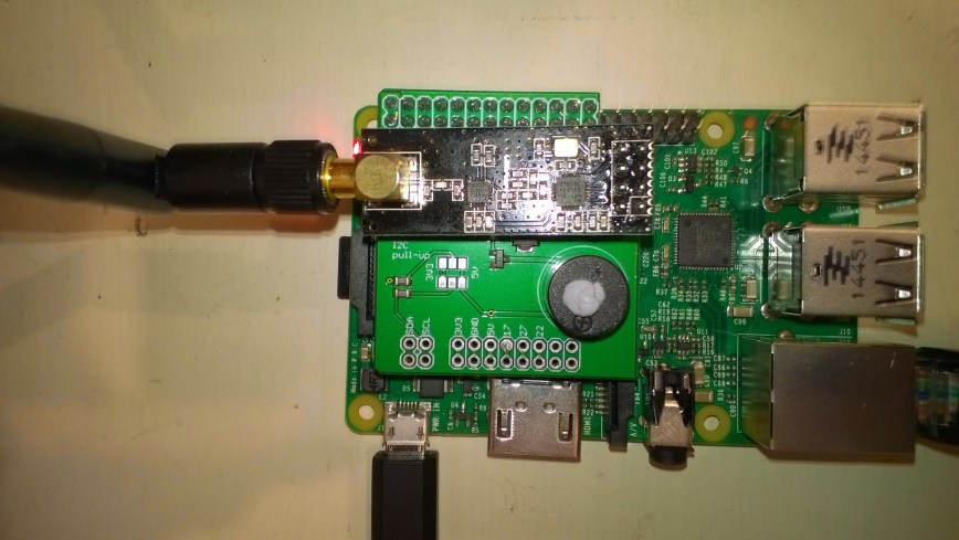
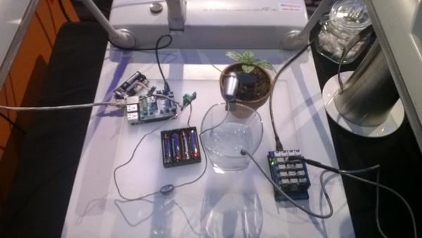
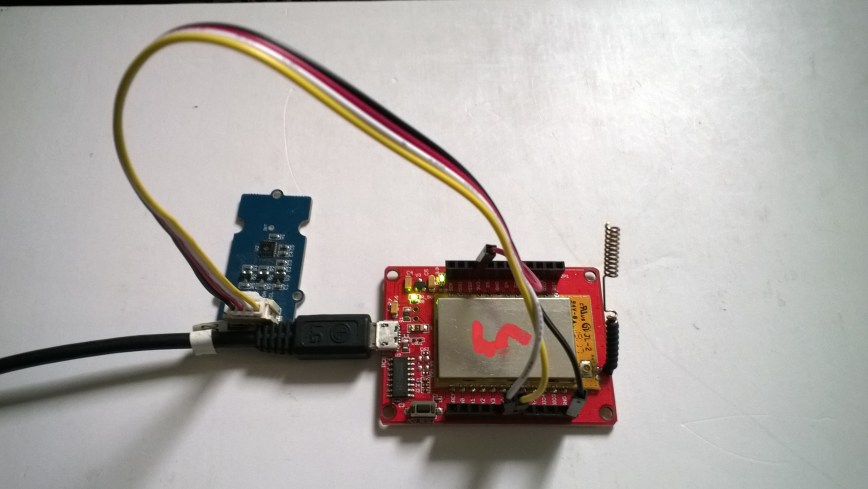
This is a demo Dragino LoRa Mini Dev featuring LoRa® technology client (based on one of the examples from Arduino-LoRa) that uploads telemetry data to my AdaFruit.IO and Azure IoT Hubs Windows 10 IoT Core on Raspberry PI proof of concept (PoC) field gateways.

LoRaMiniDevTH02

Bill of materials (Prices Sep 2018)

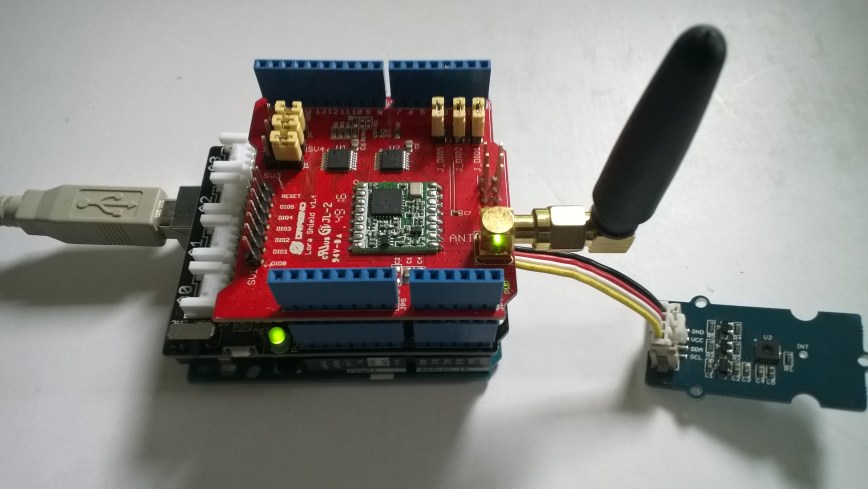
  • Draguino LoRa MiniDev USD23
  • Seeedstudio Temperature&Humidity Sensor USD11.50 NZD20
  • 4 pin Male Jumper to Grove 4 pin Conversion Cable USD2.90

The code is pretty basic, it shows how to pack the payload and set the necessary RFM9X/SX127X LoRa module configuration, has no power conservation, advanced wireless configuration etc.

The Grove 4 pin Male Jumper to Grove 4 pin Conversion Cable was a quick & convenient way to get the I2C Grove temperature and humidity sensor connected up.

/*
Adapted from LoRa Duplex communication with Sync Word

Sends temperature & humidity data from Seeedstudio

https://www.seeedstudio.com/Grove-Temperature-Humidity-Sensor-High-Accuracy-Min-p-1921.html

To my Windows 10 IoT Core RFM 9X library

https://blog.devmobile.co.nz/2018/09/03/rfm9x-iotcore-payload-addressing/

*/
#include
#include
#include
const int csPin = 10;          // LoRa radio chip select
const int resetPin = 9;       // LoRa radio reset
const int irqPin = 2;         // change for your board; must be a hardware interrupt pin

// Field gateway configuration
const byte FieldGatewayAddress[] = "LoRaIoT1";
const float FieldGatewayFrequency =  915000000.0;
//const float FieldGatewayFrequency =  433000000.0;
const byte FieldGatewaySyncWord = 0x12 ;

// Payload configuration
const int PayloadSizeMaximum = 64 ;
char payload[PayloadSizeMaximum] = "";
const byte SensorReadingSeperator = ',' ;

// Manual serial number configuration
char DeviceId[] = {"LoRaMiniDev5"};

const int LoopSleepDelaySeconds = 10 ;

void setup() {
Serial.begin(9600);
while (!Serial);

Serial.print("LoRa Setup-");
Serial.println( DeviceId ) ;

// override the default CS, reset, and IRQ pins (optional)
LoRa.setPins(csPin, resetPin, irqPin);// set CS, reset, IRQ pin

if (!LoRa.begin(FieldGatewayFrequency))
{
Serial.println("LoRa init failed. Check your connections.");
while (true);
}

// Need to do this so field gateways pays attention to messsages from this device
LoRa.enableCrc();
LoRa.setSyncWord(FieldGatewaySyncWord);

//LoRa.dumpRegisters(Serial);
Serial.println("LoRa Setup done.");

// Configure the Seeedstudio TH02 temperature & humidity sensor
Serial.println("TH02 setup");
TH02.begin();
delay(100);
Serial.println("TH02 Setup done");

Serial.println("Setup done");
}

void loop()
{
int payloadLength = 0 ;
float temperature ;
float humidity ;

Serial.println("Loop called");
memset(payload, 0, sizeof(payload));

// prepare the payload header with "To" Address length (top nibble) and "From" address length (bottom nibble)
payload[0] = (strlen(FieldGatewayAddress)<<4) | strlen( DeviceId ) ;
payloadLength += 1;

// Copy the "To" address into payload
memcpy(&payload[payloadLength], FieldGatewayAddress, strlen(FieldGatewayAddress));
payloadLength += strlen(FieldGatewayAddress) ;

// Copy the "From" into payload
memcpy(&payload[payloadLength], DeviceId, strlen(DeviceId));
payloadLength += strlen(DeviceId) ;

// Read the temperature and humidity values then display nicely
temperature = TH02.ReadTemperature();
humidity = TH02.ReadHumidity();

Serial.print("T:");
Serial.print( temperature, 1 ) ;
Serial.print( "C" ) ;

Serial.print(" H:");
Serial.print( humidity, 0 ) ;
Serial.println( "%" ) ;

// Copy the temperature into the payload
payload[ payloadLength] = 't';
payloadLength += 1 ;
payload[ payloadLength] = ' ';
payloadLength += 1 ;
payloadLength += strlen( dtostrf(temperature, -1, 1, &payload[payloadLength]));
payload[ payloadLength] = SensorReadingSeperator;
payloadLength += sizeof(SensorReadingSeperator) ;

// Copy the humidity into the payload
payload[ payloadLength] = 'h';
payloadLength += 1 ;
payload[ payloadLength] = ' ';
payloadLength += 1 ;
payloadLength += strlen( dtostrf(humidity, -1, 0, &payload[payloadLength]));

// display info about payload then send it (No ACK) with LoRa unlike nRF24L01
Serial.print( "RFM9X/SX127X Payload length:");
Serial.print( payloadLength );
Serial.println( " bytes" );

LoRa.beginPacket();
LoRa.write( payload, payloadLength );
LoRa.endPacket();

Serial.println("Loop done");

delay(LoopSleepDelaySeconds * 1000l);
}

In the debug output window the messages from the device looked like this

09:53:05-RX From LoRaMiniDev5 PacketSnr 9.3 Packet RSSI -65dBm RSSI -109dBm = 11 byte message "t 16.8,h 98"
Sensor LoRaMiniDev5t Value 16.8
Sensor LoRaMiniDev5h Value 98
AzureIoTHubClient SendEventAsync start
AzureIoTHubClient SendEventAsync finish
The thread 0xba0 has exited with code 0 (0x0).
The thread 0xb24 has exited with code 0 (0x0).
09:53:15-RX From LoRaMiniDev5 PacketSnr 9.3 Packet RSSI -65dBm RSSI -108dBm = 11 byte message "t 16.7,h 98"
Sensor LoRaMiniDev5t Value 16.7
Sensor LoRaMiniDev5h Value 98
AzureIoTHubClient SendEventAsync start
AzureIoTHubClient SendEventAsync finish
The thread 0x76c has exited with code 0 (0x0).
The thread 0x91c has exited with code 0 (0x0).

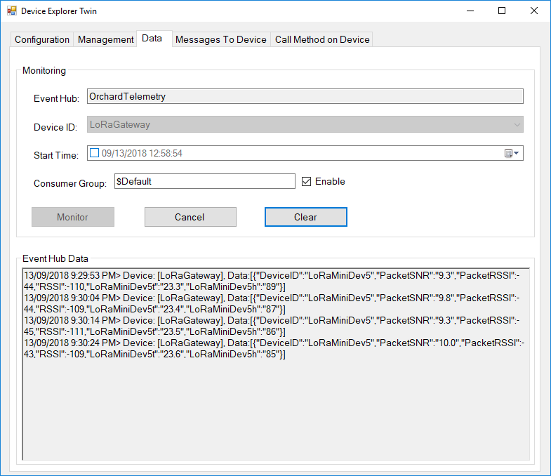
Then in my Azure IoT Hub monitoring software
DraginoLoraMinDevEventHub
The dragino LoRa Mini Dev with an external antenna connector would be a good indoor data acquisition node for student project when powered by a 2nd hand cellphone charger.

Arduino LoRa Payload Addressing Client

This is a demo Arduino client (based on one of the examples from Arduino-LoRa) that uploads telemetry data to my Windows 10 IoT Core on Raspberry PI field gateway proof of concept(PoC).

Bill of materials (Prices Sep 2018)

ArduinoUnoR3DraginoLoRa

The code is pretty basic, it shows how to pack the payload and set the necessary RFM9X/SX127X LoRa module configuration, has no power conservation, advanced wireless configuration etc.

/*
  Adapted from LoRa Duplex communication with Sync Word

  Sends temperature & humidity data from Seeedstudio 

  https://www.seeedstudio.com/Grove-Temperature-Humidity-Sensor-High-Accuracy-Min-p-1921.html

  To my Windows 10 IoT Core RFM 9X library

  https://blog.devmobile.co.nz/2018/09/03/rfm9x-iotcore-payload-addressing/

*/
#include
#include
#include
const int csPin = 10;          // LoRa radio chip select
const int resetPin = 9;       // LoRa radio reset
const int irqPin = 2;         // change for your board; must be a hardware interrupt pin

// Field gateway configuration
const byte FieldGatewayAddress[] = "LoRaIoT1";
const float FieldGatewayFrequency =  915000000.0;
const byte FieldGatewaySyncWord = 0x12 ;

// Payload configuration
const int PayloadSizeMaximum = 64 ;
char payload[PayloadSizeMaximum] = "";
const byte SensorReadingSeperator = ',' ;

// Manual serial number configuration
char DeviceId[] = {"Arduino1"};

const int LoopSleepDelaySeconds = 60;

void setup() {
  Serial.begin(9600);
  while (!Serial);

  Serial.println("LoRa Setup");

  // override the default CS, reset, and IRQ pins (optional)
  LoRa.setPins(csPin, resetPin, irqPin);// set CS, reset, IRQ pin

  if (!LoRa.begin(FieldGatewayFrequency))
  {
    Serial.println("LoRa init failed. Check your connections.");
    while (true);
  }

  // Need to do this so field gateways pays attention to messsages from this device
  LoRa.enableCrc();
  LoRa.setSyncWord(FieldGatewaySyncWord);  

  //LoRa.dumpRegisters(Serial);
  Serial.println("LoRa Setup done.");

  // Configure the Seeedstudio TH02 temperature & humidity sensor
  Serial.println("TH02 setup");
  TH02.begin();
  delay(100);
  Serial.println("TH02 Setup done");  

  Serial.println("Setup done");
}

void loop()
{
  int payloadLength = 0 ;
  float temperature ;
  float humidity ;

  Serial.println("Loop called");
  memset(payload, 0, sizeof(payload));

  // prepare the payload header with "To" Address length (top nibble) and "From" address length (bottom nibble)
  payload[0] = (strlen(FieldGatewayAddress) << 4) | strlen( DeviceId ) ;
  payloadLength += 1;

  // Copy the "To" address into payload
  memcpy(&payload[payloadLength], FieldGatewayAddress, strlen(FieldGatewayAddress));
  payloadLength += strlen(FieldGatewayAddress) ;

  // Copy the "From" into payload
  memcpy(&payload[payloadLength], DeviceId, strlen(DeviceId));
  payloadLength += strlen(DeviceId) ;

  // Read the temperature and humidity values then display nicely
  temperature = TH02.ReadTemperature();
  humidity = TH02.ReadHumidity();

  Serial.print("T:");
  Serial.print( temperature, 1 ) ;
  Serial.print( "C" ) ;

  Serial.print(" H:");
  Serial.print( humidity, 0 ) ;
  Serial.println( "%" ) ;

  // Copy the temperature into the payload
  payload[ payloadLength] = 't';
  payloadLength += 1 ;
  payload[ payloadLength] = ' ';
  payloadLength += 1 ;
  payloadLength += strlen( dtostrf(temperature, -1, 1, &payload[payloadLength]));
  payload[ payloadLength] = SensorReadingSeperator;
  payloadLength += sizeof(SensorReadingSeperator) ;

  // Copy the humidity into the payload
  payload[ payloadLength] = 'h';
  payloadLength += 1 ;
  payload[ payloadLength] = ' ';
  payloadLength += 1 ;
  payloadLength += strlen( dtostrf(humidity, -1, 0, &payload[payloadLength]));  

  // display info about payload then send it (No ACK) with LoRa unlike nRF24L01
  Serial.print( "RFM9X/SX127X Payload length:");
  Serial.print( payloadLength );
  Serial.println( " bytes" );

  LoRa.beginPacket();
  LoRa.write( payload, payloadLength );
  LoRa.endPacket();      

  Serial.println("Loop done");

  delay(LoopSleepDelaySeconds * 1000l);
}

In the debug output window the messages from the device looked like this

Register 0x40 – Value 0X00 – Bits 00000000
Register 0x41 – Value 0X00 – Bits 00000000
Register 0x42 – Value 0X12 – Bits 00010010

19:15:21-RX From Arduino1 PacketSnr 9.3 Packet RSSI -49dBm RSSI -105dBm = 11 byte message "t 18.8,h 91"

19:15:30-TX 25 byte message Hello from LoRaIoT1 ! 255
19:15:30-TX Done
19:15:31-RX From Arduino1 PacketSnr 9.3 Packet RSSI -49dBm RSSI -103dBm = 11 byte message "t 18.8,h 91"

19:15:41-RX From Arduino1 PacketSnr 9.3 Packet RSSI -48dBm RSSI -106dBm = 11 byte message "t 18.8,h 91"

There must be a nicer way of building the payload, a topic for a future post maybe.

M2M Low power LoRaWan Node Model B1284

Along with the M2M LoRaWan Gateway Shield for Raspberry Pi I also purchased a Low power LoRaWan Node Model B1284. After configuring Arduino IDE then downloading the necessary board configuration files (link to instructions was provided) I could down upload my Arduino-Lora based test application .

LoRaWanNodeV1_0.jpg
Initially the program failed with “LoRa init failed. Check your connections.” so I went back and checked the board configuration details and noticed that the chip select line was different.

const int csPin = 14;          // LoRa radio chip select
const int resetPin = 9;       // LoRa radio reset
const int irqPin = 2;         // change for your board; must be a hardware interrupt pin

byte msgCount = 0;            // count of outgoing messages
int interval = 2000;          // interval between sends
long lastSendTime = 0;        // time of last packet send

void setup() {
  Serial.begin(9600);                   // initialize serial
  while (!Serial);

  Serial.println("LoRa Duplex - Set sync word");

  // override the default CS, reset, and IRQ pins (optional)
  LoRa.setPins(csPin, resetPin, irqPin);// set CS, reset, IRQ pin

  if (!LoRa.begin(915E6)) {             // initialize ratio at 915 MHz
    Serial.println("LoRa init failed. Check your connections.");
    while (true);                       // if failed, do nothing
  }

  LoRa.enableCrc();

  LoRa.setSyncWord(0x12);           // ranges from 0-0xFF, default 0x34, see API docs

  LoRa.dumpRegisters(Serial);
  Serial.println("LoRa init succeeded.");
}

void loop() {
  if (millis() - lastSendTime > interval) {
    String message = "11 Hello Arduino LoRa! ";   // send a message
    message += msgCount;
    sendMessage(message);
    Serial.println("Sending " + message);
    lastSendTime = millis();            // timestamp the message
    //interval = random(2000) + 1000;    // 2-3 seconds
    interval = 1000;
  }

  // parse for a packet, and call onReceive with the result:
  onReceive(LoRa.parsePacket());
}

void sendMessage(String outgoing) {
  LoRa.beginPacket();                   // start packet
  LoRa.print(outgoing);                 // add payload
  LoRa.endPacket();                     // finish packet and send it
  msgCount++;                           // increment message ID
}

void onReceive(int packetSize) {
  if (packetSize == 0) return;          // if there's no packet, return

  // read packet header bytes:
  String incoming = "";

  while (LoRa.available()) {
    incoming += (char)LoRa.read();
  }

  Serial.println("Message: " + incoming);
  Serial.println("RSSI: " + String(LoRa.packetRssi()));
  Serial.println("Snr: " + String(LoRa.packetSnr()));
  Serial.println();
}

When I uploaded my application I found the device had significantly more memory available

Sketch uses 8456 bytes (27%) of program storage space. Maximum is 30720 bytes.
vs..
Sketch uses 10424 bytes (8%) of program storage space. Maximum is 130048 bytes.

With the size of the LMIC stack this additional extra headroom could be quite useful. For most my LoRa applications (which tend to be a couple of simple sensors) I think the Low Power LoRaWan Node Model A328 should be sufficient.

M2M LoRaWan Node Model A328

Along with the M2M LoRaWan Gateway Shield for Raspberry Pi I also purchased a Low power LoRaWan Node Model A328. After setting the Board in Arduino IDE to Arduino pro mini 8Mhz 3V the device fired up and worked first time.

LoRaWanNodeV3_5
The device is intended for LoRaWan applications so the samples provided (including a link to application template generator) were not that applicable for my LoRa project so I used the Arduino LoRa library.

const int csPin = 10;          // LoRa radio chip select
const int resetPin = 9;       // LoRa radio reset
const int irqPin = 2;         // change for your board; must be a hardware interrupt pin

byte msgCount = 0;            // count of outgoing messages
int interval = 2000;          // interval between sends
long lastSendTime = 0;        // time of last packet send

void setup() {
  Serial.begin(9600);                   // initialize serial
  while (!Serial);

  Serial.println("LoRa Duplex - Set sync word");

  // override the default CS, reset, and IRQ pins (optional)
  LoRa.setPins(csPin, resetPin, irqPin);// set CS, reset, IRQ pin

  if (!LoRa.begin(915E6)) {             // initialize ratio at 915 MHz
    Serial.println("LoRa init failed. Check your connections.");
    while (true);                       // if failed, do nothing
  }

  LoRa.enableCrc();

  LoRa.setSyncWord(0x12);           // ranges from 0-0xFF, default 0x34, see API docs

  LoRa.dumpRegisters(Serial);
  Serial.println("LoRa init succeeded.");
}

void loop() {
  if (millis() - lastSendTime > interval) {
    String message = "0 Hello Arduino LoRa! ";   // send a message
    message += msgCount;
    sendMessage(message);
    Serial.println("Sending " + message);
    lastSendTime = millis();            // timestamp the message
    //interval = random(2000) + 1000;    // 2-3 seconds
    interval = 1000;
  }

  // parse for a packet, and call onReceive with the result:
  onReceive(LoRa.parsePacket());
}

void sendMessage(String outgoing) {
  LoRa.beginPacket();                   // start packet
  LoRa.print(outgoing);                 // add payload
  LoRa.endPacket();                     // finish packet and send it
  msgCount++;                           // increment message ID
}

void onReceive(int packetSize) {
  if (packetSize == 0) return;          // if there's no packet, return

  // read packet header bytes:
  String incoming = "";

  while (LoRa.available()) {
    incoming += (char)LoRa.read();
  }

  Serial.println("Message: " + incoming);
  Serial.println("RSSI: " + String(LoRa.packetRssi()));
  Serial.println("Snr: " + String(LoRa.packetSnr()));
  Serial.println();
}

I did find the “grove” connectors weren’t compatible with any of my sensors, but the vendor does include a number of cables DIY connection.

GroveConnectorIssue20180822

Next I’ll use power conservation modes and see how long I can get a set of AAA batteries to last. The device looks like a good option (esp. with solar power for devices with higher power consumption sensors) for some of the SmartAg projects my students are building.

In my Windows 10 IoT Core test application I could see the enableCrc() method was working according to the RegHopChannel CrcOnPayload flag.

For real deployments of the field gateway I think packets which have no CRC or a corrupted one will be dropped.

RFM95/96/97/98 shield library Part5


Receive Basic

The receive code worked reliably after a couple of attempts. Initially, I was setting the RxTimeout bit on the RegIrqFlags register after retrieving the message, rather than the RxDone bit, and then found I was setting the receive single rather than receive continuous bit of RegOpMode.

I did some basic stress testing with a number of Arduino devices running a slightly modified version of the LoRaSetSyncWord example and my C# code didn’t appear to be dropping messages.

//---------------------------------------------------------------------------------
// Copyright (c) August 2018, devMobile Software
//
// Licensed under the Apache License, Version 2.0 (the "License");
// you may not use this file except in compliance with the License.
// You may obtain a copy of the License at
//
//     http://www.apache.org/licenses/LICENSE-2.0
//
// Unless required by applicable law or agreed to in writing, software
// distributed under the License is distributed on an "AS IS" BASIS,
// WITHOUT WARRANTIES OR CONDITIONS OF ANY KIND, either express or implied.
// See the License for the specific language governing permissions and
// limitations under the License.
//
//---------------------------------------------------------------------------------
namespace devMobile.IoT.Rfm9x.ReceiveBasic
{
   using System;
   using System.Diagnostics;
   using System.Text;
   using System.Runtime.InteropServices.WindowsRuntime;
   using System.Threading.Tasks;
   using Windows.ApplicationModel.Background;
   using Windows.Devices.Spi;
   using Windows.Devices.Gpio;

   public sealed class Rfm9XDevice
   {
      private SpiDevice Rfm9XLoraModem = null;
      private GpioPin ChipSelectGpioPin = null;
      private const byte RegisterAddressReadMask = 0X7f;
      private const byte RegisterAddressWriteMask = 0x80;

      public Rfm9XDevice(byte chipSelectPin, byte resetPin)
      {
         SpiController spiController = SpiController.GetDefaultAsync().AsTask().GetAwaiter().GetResult();
         var settings = new SpiConnectionSettings(0)
         {
            ClockFrequency = 500000,
            Mode = SpiMode.Mode0,
         };

         // Chip select pin configuration
         GpioController gpioController = GpioController.GetDefault();
         ChipSelectGpioPin = gpioController.OpenPin(chipSelectPin);
         ChipSelectGpioPin.SetDriveMode(GpioPinDriveMode.Output);
         ChipSelectGpioPin.Write(GpioPinValue.High);

         // Reset pin configuration to do factory reset
         GpioPin resetGpioPin = gpioController.OpenPin(resetPin);
         resetGpioPin.SetDriveMode(GpioPinDriveMode.Output);
         resetGpioPin.Write(GpioPinValue.Low);
         Task.Delay(10);
         resetGpioPin.Write(GpioPinValue.High);
         Task.Delay(10);

         Rfm9XLoraModem = spiController.GetDevice(settings);
         }

	public Byte RegisterReadByte(byte address)
	{
		byte[] writeBuffer = new byte[] { address &= RegisterAddressReadMask };
		byte[] readBuffer = new byte[1];
		Debug.Assert(Rfm9XLoraModem != null);

		ChipSelectGpioPin.Write(GpioPinValue.Low);
		Rfm9XLoraModem.Write(writeBuffer);
		Rfm9XLoraModem.Read(readBuffer);
		ChipSelectGpioPin.Write(GpioPinValue.High);

		return readBuffer[0];
	}

	public ushort RegisterReadWord(byte address)
	{
		byte[] writeBuffer = new byte[] { address &= RegisterAddressReadMask };
		byte[] readBuffer = new byte[2];
		Debug.Assert(Rfm9XLoraModem != null);

		ChipSelectGpioPin.Write(GpioPinValue.Low);
		Rfm9XLoraModem.Write(writeBuffer);
		Rfm9XLoraModem.Read(readBuffer);
		ChipSelectGpioPin.Write(GpioPinValue.High);

		return (ushort)(readBuffer[1] + (readBuffer[0] << 8));
	}

	public byte[] RegisterRead(byte address, int length)
	{
		byte[] writeBuffer = new byte[] { address &= RegisterAddressReadMask };
		byte[] readBuffer = new byte[length];
		Debug.Assert(Rfm9XLoraModem != null);

		ChipSelectGpioPin.Write(GpioPinValue.Low);
		Rfm9XLoraModem.Write(writeBuffer);
		Rfm9XLoraModem.Read(readBuffer);
		ChipSelectGpioPin.Write(GpioPinValue.High);

		return readBuffer;
	}

	public void RegisterWriteByte(byte address, byte value)
	{
		byte[] writeBuffer = new byte[] { address |= RegisterAddressWriteMask, value };
		Debug.Assert(Rfm9XLoraModem != null);

		ChipSelectGpioPin.Write(GpioPinValue.Low);
		Rfm9XLoraModem.Write(writeBuffer);
		ChipSelectGpioPin.Write(GpioPinValue.High);
	}

	public void RegisterWriteWord(byte address, ushort value)
	{
		byte[] valueBytes = BitConverter.GetBytes(value);
		byte[] writeBuffer = new byte[] { address |= RegisterAddressWriteMask, valueBytes[0], valueBytes[1] };
		Debug.Assert(Rfm9XLoraModem != null);

		ChipSelectGpioPin.Write(GpioPinValue.Low);
		Rfm9XLoraModem.Write(writeBuffer);
		ChipSelectGpioPin.Write(GpioPinValue.High);
	}

	public void RegisterWrite(byte address, [ReadOnlyArray()] byte[] bytes)
	{
		byte[] writeBuffer = new byte[1 + bytes.Length];
		Debug.Assert(Rfm9XLoraModem != null);

		Array.Copy(bytes, 0, writeBuffer, 1, bytes.Length);
		writeBuffer[0] = address |= RegisterAddressWriteMask;

		ChipSelectGpioPin.Write(GpioPinValue.Low);
		Rfm9XLoraModem.Write(writeBuffer);
		ChipSelectGpioPin.Write(GpioPinValue.High);
	}

	public void RegisterDump()
	{
		Debug.WriteLine("Register dump");
		for (byte registerIndex = 0; registerIndex <= 0x42; registerIndex++)
		{
			byte registerValue = this.RegisterReadByte(registerIndex);

			Debug.WriteLine("Register 0x{0:x2} - Value 0X{1:x2} - Bits {2}", registerIndex, registerValue, Convert.ToString(registerValue, 2).PadLeft(8, '0'));
		}
	}
}

public sealed class StartupTask : IBackgroundTask
{
	private const int ChipSelectLine = 25;
	private const int ResetLine = 17;
	private Rfm9XDevice rfm9XDevice = new Rfm9XDevice(ChipSelectLine, ResetLine);

	public void Run(IBackgroundTaskInstance taskInstance)
	{
		// Put device into LoRa + Sleep mode
		rfm9XDevice.RegisterWriteByte(0x01, 0b10000000); // RegOpMode 

		// Set the frequency to 915MHz
		byte[] frequencyWriteBytes = { 0xE4, 0xC0, 0x00 }; // RegFrMsb, RegFrMid, RegFrLsb
		rfm9XDevice.RegisterWrite(0x06, frequencyWriteBytes);

		rfm9XDevice.RegisterWriteByte(0x0F, 0x0); // RegFifoRxBaseAddress 

		rfm9XDevice.RegisterWriteByte(0x01, 0b10000101); // RegOpMode set LoRa & RxContinuous

		while (true)
		{
			// Wait until a packet is received, no timeouts in PoC
			Debug.WriteLine("Receive-Wait");
			byte IrqFlags = rfm9XDevice.RegisterReadByte(0x12); // RegIrqFlags
			while ((IrqFlags & 0b01000000) == 0)  // wait until RxDone cleared
			{
				Task.Delay(20).Wait();
				IrqFlags = rfm9XDevice.RegisterReadByte(0x12); // RegIrqFlags
				Debug.Write(".");
			}
			Debug.WriteLine("");

			Debug.WriteLine("Receive-Message");
			byte currentFifoAddress = rfm9XDevice.RegisterReadByte(0x10); // RegFifiRxCurrent
			rfm9XDevice.RegisterWriteByte( 0x0d, currentFifoAddress); // RegFifoAddrPtr

			byte numberOfBytes = rfm9XDevice.RegisterReadByte(0x13); // RegRxNbBytes

			// Allocate buffer for message
			byte[] messageBytes = new byte[numberOfBytes];

			for (int i = 0; I < numberOfBytes; i++)
			{
				messageBytes[i] = rfm9XDevice.RegisterReadByte(0x00); // RegFifo
			}
            string messageText = UTF8Encoding.UTF8.GetString(messageBytes);
            Debug.WriteLine("Received {0} byte message {1}", messageBytes.Length, messageText);

            rfm9XDevice.RegisterWriteByte(0x12, 0b01000000); // RegIrqFlags clear RxDone bit

            Debug.WriteLine("Receive-Done");
         }
      }
   }
}

With 3 client devices transmitting the debug output looked like this

Receive-Wait

Receive-Message
Received 16 byte message HeLoRa World! 14
Receive-Done
Receive-Wait
……………………………………………………
Receive-Message
Received 16 byte message HeLoRa World! 16
Receive-Done
Receive-Wait
………………………………………………………………………………….
Receive-Message
Received 16 byte message HeLoRa World! 18
Receive-Done
Receive-Wait
………………………………………………………………………….
Receive-Message
Received 16 byte message HeLoRa World! 20
Receive-Done
Receive-Wait
………………
Receive-Message
Received 16 byte message HelloRa World! 0
Receive-Done
Receive-Wait
………………………
Receive-Message
Received 16 byte message HeLoRa World! 22
Receive-Done
Receive-Wait

Most LoRa libraries include the Received Signal Strength Indication(RSSI) & Signal To noise ratio (SNR) information with the received packet. The RSSI needs to be “adjusted” by a constant depending on the frequency so that can wait until after configuration approach has been decided.

Transmitting/receiving with interrupts or design goals next.

RFM95/96/97/98 shield library Part4

Transmit Basic

Slight change of plan I decided that proving I could send a message and interoperability with another LoRa stack would be more interesting…

My first attempt didn’t have much range so I tried turning on the PA_BOOST pin (in RegPaConfig) which improved the range and Received Signal Strength Indication (RSSI) on my Arduino client (equipped with Dragino shield). This was running the Arduino LoRa library LoRaSetSyncWord example.

/*
  LoRa Duplex communication with Sync Word

  Sends a message every half second, and polls continually
  for new incoming messages. Sets the LoRa radio's Sync Word.

  Spreading factor is basically the radio's network ID. Radios with different
  Sync Words will not receive each other's transmissions. This is one way you
  can filter out radios you want to ignore, without making an addressing scheme.

  See the Semtech datasheet, http://www.semtech.com/images/datasheet/sx1276.pdf
  for more on Sync Word.

  created 28 April 2017
  by Tom Igoe
*/
#include
#include
const int csPin = 10;          // LoRa radio chip select
const int resetPin = 9;       // LoRa radio reset
const int irqPin = 2;         // change for your board; must be a hardware interrupt pin

byte msgCount = 0;            // count of outgoing messages
int interval = 2000;          // interval between sends
long lastSendTime = 0;        // time of last packet send

void setup() {
  Serial.begin(9600);                   // initialize serial
  while (!Serial);

  Serial.println("LoRa Duplex - Set sync word");

  // override the default CS, reset, and IRQ pins (optional)
  LoRa.setPins(csPin, resetPin, irqPin);// set CS, reset, IRQ pin

  if (!LoRa.begin(915E6)) {             // initialize ratio at 915 MHz
    Serial.println("LoRa init failed. Check your connections.");
    while (true);                       // if failed, do nothing
  }

  LoRa.setSyncWord(0x12);           // ranges from 0-0xFF, default 0x34, see API docs

  LoRa.dumpRegisters(Serial);
  Serial.println("LoRa init succeeded.");
}

void loop() {
  if (millis() - lastSendTime > interval) {
    String message = "HeLoRa World! ";   // send a message
    message += msgCount;
    sendMessage(message);
    Serial.println("Sending " + message);
    lastSendTime = millis();            // timestamp the message
    interval = random(2000) + 1000;    // 2-3 seconds
    msgCount++;
  }

  // parse for a packet, and call onReceive with the result:
  onReceive(LoRa.parsePacket());
}

void sendMessage(String outgoing) {
  LoRa.beginPacket();                   // start packet
  LoRa.print(outgoing);                 // add payload
  LoRa.endPacket();                     // finish packet and send it
  msgCount++;                           // increment message ID
}

void onReceive(int packetSize) {
  if (packetSize == 0) return;          // if there's no packet, return

  // read packet header bytes:
  String incoming = "";

  while (LoRa.available()) {
    incoming += (char)LoRa.read();
  }

  Serial.println("Message: " + incoming);
  Serial.println("RSSI: " + String(LoRa.packetRssi()));
  Serial.println("Snr: " + String(LoRa.packetSnr()));
  Serial.println();
}

The Windows 10 IoT core application

//---------------------------------------------------------------------------------
// Copyright (c) August 2018, devMobile Software
//
// Licensed under the Apache License, Version 2.0 (the "License");
// you may not use this file except in compliance with the License.
// You may obtain a copy of the License at
//
//     http://www.apache.org/licenses/LICENSE-2.0
//
// Unless required by applicable law or agreed to in writing, software
// distributed under the License is distributed on an "AS IS" BASIS,
// WITHOUT WARRANTIES OR CONDITIONS OF ANY KIND, either express or implied.
// See the License for the specific language governing permissions and
// limitations under the License.
//
//---------------------------------------------------------------------------------
namespace devMobile.IoT.Rfm9x.TransmitBasic
{
   using System;
   using System.Diagnostics;
   using System.Text;
   using System.Runtime.InteropServices.WindowsRuntime;
   using System.Threading.Tasks;
   using Windows.ApplicationModel.Background;
   using Windows.Devices.Spi;
   using Windows.Devices.Gpio;

	public sealed class Rfm9XDevice
	{
		private SpiDevice Rfm9XLoraModem = null;
		private GpioPin ChipSelectGpioPin = null;
		private const byte RegisterAddressReadMask = 0X7f;
		private const byte RegisterAddressWriteMask = 0x80;

		public Rfm9XDevice(byte chipSelectPin, byte resetPin)
		{
			SpiController spiController = SpiController.GetDefaultAsync().AsTask().GetAwaiter().GetResult();
			var settings = new SpiConnectionSettings(0)
			{
				ClockFrequency = 500000,
				Mode = SpiMode.Mode0,
			};

			// Chip select pin configuration
			GpioController gpioController = GpioController.GetDefault();
			ChipSelectGpioPin = gpioController.OpenPin(chipSelectPin);
			ChipSelectGpioPin.SetDriveMode(GpioPinDriveMode.Output);
			ChipSelectGpioPin.Write(GpioPinValue.High);

			// Reset pin configuration for factory reset
			GpioPin resetGpioPin = gpioController.OpenPin(resetPin);
			resetGpioPin.SetDriveMode(GpioPinDriveMode.Output);
			resetGpioPin.Write(GpioPinValue.Low);
			Task.Delay(10);
			resetGpioPin.Write(GpioPinValue.High);
			Task.Delay(10);

			Rfm9XLoraModem = spiController.GetDevice(settings);
		}

		public Byte RegisterReadByte(byte address)
		{
			byte[] writeBuffer = new byte[] { address &= RegisterAddressReadMask };
			byte[] readBuffer = new byte[1];
			Debug.Assert(Rfm9XLoraModem != null);

			ChipSelectGpioPin.Write(GpioPinValue.Low);
			Rfm9XLoraModem.Write(writeBuffer);
			Rfm9XLoraModem.Read(readBuffer);
			ChipSelectGpioPin.Write(GpioPinValue.High);

			return readBuffer[0];
		}

		public ushort RegisterReadWord(byte address)
		{
			byte[] writeBuffer = new byte[] { address &= RegisterAddressReadMask };
			byte[] readBuffer = new byte[2];
			Debug.Assert(Rfm9XLoraModem != null);

			ChipSelectGpioPin.Write(GpioPinValue.Low);
			Rfm9XLoraModem.Write(writeBuffer);
			Rfm9XLoraModem.Read(readBuffer);
			ChipSelectGpioPin.Write(GpioPinValue.High);

			return (ushort)(readBuffer[1] + (readBuffer[0] << 8));
		}

		public byte[] RegisterRead(byte address, int length)
		{
			byte[] writeBuffer = new byte[] { address &= RegisterAddressReadMask };
			byte[] readBuffer = new byte[length];
			Debug.Assert(Rfm9XLoraModem != null);

			ChipSelectGpioPin.Write(GpioPinValue.Low);
			Rfm9XLoraModem.Write(writeBuffer);
			Rfm9XLoraModem.Read(readBuffer);
			ChipSelectGpioPin.Write(GpioPinValue.High);

			return readBuffer;
		}

		public void RegisterWriteByte(byte address, byte value)
		{
			byte[] writeBuffer = new byte[] { address |= RegisterAddressWriteMask, value };
			Debug.Assert(Rfm9XLoraModem != null);

			ChipSelectGpioPin.Write(GpioPinValue.Low);
			Rfm9XLoraModem.Write(writeBuffer);
			ChipSelectGpioPin.Write(GpioPinValue.High);
		}

		public void RegisterWriteWord(byte address, ushort value)
		{
			byte[] valueBytes = BitConverter.GetBytes(value);
			byte[] writeBuffer = new byte[] { address |= RegisterAddressWriteMask, valueBytes[0], valueBytes[1] };
			Debug.Assert(Rfm9XLoraModem != null);

			ChipSelectGpioPin.Write(GpioPinValue.Low);
			Rfm9XLoraModem.Write(writeBuffer);
			ChipSelectGpioPin.Write(GpioPinValue.High);
		}

		public void RegisterWrite(byte address, [ReadOnlyArray()] byte[] bytes)
		{
			byte[] writeBuffer = new byte[1 + bytes.Length];
			Debug.Assert(Rfm9XLoraModem != null);

			Array.Copy(bytes, 0, writeBuffer, 1, bytes.Length);
			writeBuffer[0] = address |= RegisterAddressWriteMask;

			ChipSelectGpioPin.Write(GpioPinValue.Low);
			Rfm9XLoraModem.Write(writeBuffer);
			ChipSelectGpioPin.Write(GpioPinValue.High);
		}

		public void RegisterDump()
		{
			Debug.WriteLine("Register dump");
			for (byte registerIndex = 0; registerIndex <= 0x42; registerIndex++)
			{
				byte registerValue = this.RegisterReadByte(registerIndex);

				Debug.WriteLine("Register 0x{0:x2} - Value 0X{1:x2} - Bits {2}", registerIndex, registerValue, Convert.ToString(registerValue, 2).PadLeft(8, '0'));
			}
		}
	}

	public sealed class StartupTask : IBackgroundTask
	{
		private const byte ChipSelectLine = 25;
		private const byte ResetLine = 17;
		private Rfm9XDevice rfm9XDevice = new Rfm9XDevice(ChipSelectLine, ResetLine);

		public void Run(IBackgroundTaskInstance taskInstance)
		{
			// Put device into LoRa + Sleep mode
			rfm9XDevice.RegisterWriteByte(0x01, 0b10000000); // RegOpMode 

			// Set the frequency to 915MHz
			byte[] frequencyWriteBytes = { 0xE4, 0xC0, 0x00 }; // RegFrMsb, RegFrMid, RegFrLsb
			rfm9XDevice.RegisterWrite(0x06, frequencyWriteBytes);

			// More power - PA_BOOST
			rfm9XDevice.RegisterWriteByte(0x09, 0b10000000); // RegPaConfig

			while (true)
			{
				rfm9XDevice.RegisterWriteByte(0x0E, 0x0); // RegFifoTxBaseAddress 

				// Set the Register Fifo address pointer
				rfm9XDevice.RegisterWriteByte(0x0D, 0x0); // RegFifoAddrPtr 

				string messageText = "Hello LoRa!";

				// load the message into the fifo
				byte[] messageBytes = UTF8Encoding.UTF8.GetBytes(messageText);
				foreach ( byte b in messageBytes )
				{
					rfm9XDevice.RegisterWriteByte(0x0, b); // RegFifo
				}

				// Set the length of the message in the fifo
				rfm9XDevice.RegisterWriteByte(0x22, (byte)messageBytes.Length); // RegPayloadLength

				Debug.WriteLine("Sending {0} bytes message {1}", messageBytes.Length, messageText);
				/// Set the mode to LoRa + Transmit
				rfm9XDevice.RegisterWriteByte(0x01, 0b10000011); // RegOpMode 

				// Wait until send done, no timeouts in PoC
				Debug.WriteLine("Send-wait");
				byte IrqFlags = rfm9XDevice.RegisterReadByte(0x12); // RegIrqFlags
				while((IrqFlags & 0b00001000) == 0 )  // wait until TxDone cleared
				{
					Task.Delay(10).Wait();
					IrqFlags = rfm9XDevice.RegisterReadByte(0x12); // RegIrqFlags
					Debug.Write(".");
				}
				Debug.WriteLine("");
				rfm9XDevice.RegisterWriteByte(0x12, 0b00001000); // clear TxDone bit
				Debug.WriteLine( "Send-Done");

				Task.Delay(30000).Wait();
			}
		}
	}
}

This PoC code is starting to get a bit nasty with magic numbers and no error checking. Next steps are either some refactoring or getting a basic packet receive working…

Wireless field gateway protocol V1

I’m going to build a number of nRF2L01P field gateways (Netduino Ethernet & Wifi running .NetMF, Raspberry PI running Windows 10 IoT Core, RedBearLab 3200  etc.), clients which run on a variety of hardware (Arduino, devDuino, Netduino, Seeeduino etc.) which, then upload data to a selection of IoT Cloud services (AdaFruit.IO, ThingSpeak, Microsoft IoT Central etc.)

The nRF24L01P is widely supported with messages up to 32 bytes long, low power consumption and 250kbps, 1Mbps and 2Mbps data rates.

The aim is to keep the protocol simple (telemetry only initially) to implement and debug as the client side code will be utilised by high school student projects.

The first byte of the message specifies the message type

0 = Echo

The message is displayed by the field gateway as text & hexadecimal.

1 = Device identifier + Comma separated values (CSV) payload

[0] – Set to 1

[1] – Device identifier length

[2]..[2+Device identifier length] – Unique device identifier bytes e.g. Mac address

[2+Device identifier length+1 ]..[31] – CSV payload e.g.  SensorID value, SensorID value

Overtime I will support more message types and wireless protocols.


nRF24 Windows 10 IoT Core reboot

My first live deployment of the nRF24L01 Windows 10 IoT Core field gateway is now scheduled for mid Q1 2018 so time for a reboot. After digging out my Raspbery PI 2/3 devices and the nRF24L01+ shield (with modifications detailed here) I have a basic plan with some milestones.

My aim is to be able to wirelessly acquire data from several dozen Arduino, devduino, seeeduino, and Netduino devices, Then, using a field gateway on a Raspberry PI running Windows 10 IoT Core upload it to Microsoft IoT Central

First bit of code – Bleepy a simple background application to test the piezo beeper on the RPI NRF24 Shield

namespace devmobile.IoTCore.Bleepy
{
   public sealed class StartupTask : IBackgroundTask
   {
      private BackgroundTaskDeferral deferral;
      private const int ledPinNumber = 4;
      private GpioPin ledGpioPin;
      private ThreadPoolTimer timer;

      public void Run(IBackgroundTaskInstance taskInstance)
      {
         var gpioController = GpioController.GetDefault();
         if (gpioController == null)
         {
            Debug.WriteLine("GpioController.GetDefault failed");
            return;
         }

         ledGpioPin = gpioController.OpenPin(ledPinNumber);
         if (ledGpioPin == null)
         {
            Debug.WriteLine("gpioController.OpenPin failed");
            return;
         }

         ledGpioPin.SetDriveMode(GpioPinDriveMode.Output);

         this.timer = ThreadPoolTimer.CreatePeriodicTimer(Timer_Tick, TimeSpan.FromMilliseconds(500));

         deferral = taskInstance.GetDeferral();

         Debug.WriteLine("Rum completed");
      }

      private void Timer_Tick(ThreadPoolTimer timer)
      {
         GpioPinValue currentPinValue = ledGpioPin.Read();

         if (currentPinValue == GpioPinValue.High)
         {
            ledGpioPin.Write(GpioPinValue.Low);
         }
         else
         {
            ledGpioPin.Write(GpioPinValue.High);
         }
      }
   }
}

Note the blob of blu tack over the piezo beeper to mute noise
nRF24ShieldMuted

nRF24 Windows 10 IoT Core Test Harness

After modifying the Raspbery PI nRF24L01 shields I built a single page single button Universal Windows Platforms(UWP) test harness (using the techfooninja RF24 library) to check everything was working as expected.

I used a couple of Netduinos and Raspbery PI devices to as test clients.

public sealed partial class MainPage : Page
{
   private const byte ChipEnablePin = 25;
   private const byte ChipSelectPin = 0;
   private const byte InterruptPin = 17;
   private const byte Channel = 10;
   private RF24 radio;

   public MainPage()
   {
      this.InitializeComponent();

      this.radio = new RF24();

      this.radio.OnDataReceived += this.Radio_OnDataReceived;
      this.radio.OnTransmitFailed += this.Radio_OnTransmitFailed;
      this.radio.OnTransmitSuccess += this.Radio_OnTransmitSuccess;

      this.radio.Initialize(ChipEnablePin, ChipSelectPin, InterruptPin);
      this.radio.Address = Encoding.UTF8.GetBytes("Base1");
      this.radio.Channel = Channel;
      this.radio.PowerLevel = PowerLevel.Low;
      this.radio.DataRate = DataRate.DR250Kbps;

      this.radio.IsEnabled = true;

      Debug.WriteLine("Address: " + Encoding.UTF8.GetString(this.radio.Address));
      Debug.WriteLine("Channel: " + this.radio.Channel);
      Debug.WriteLine("DataRate: " + this.radio.DataRate);
      Debug.WriteLine("PA: " + this.radio.PowerLevel);
      Debug.WriteLine("IsAutoAcknowledge: " + this.radio.IsAutoAcknowledge);
      Debug.WriteLine("IsDynamicAcknowledge: " + this.radio.IsDynamicAcknowledge);
      Debug.WriteLine("IsDynamicPayload: " + this.radio.IsDynamicPayload);
      Debug.WriteLine("IsEnabled: " + this.radio.IsEnabled);
      Debug.WriteLine("IsInitialized: " + this.radio.IsInitialized);
      Debug.WriteLine("IsPowered: " + this.radio.IsPowered);
   }

   private void Radio_OnDataReceived(byte[] data)
   {
     string dataUTF8 = Encoding.UTF8.GetString(data);

     Debug.WriteLine(string.Format("Received: {0}", dataUTF8));
   }

   private void buttonSend_Click(object sender, Windows.UI.Xaml.RoutedEventArgs e)
   {
      this.radio.SendTo(Encoding.UTF8.GetBytes("Duino"), Encoding.UTF8.GetBytes(DateTime.UtcNow.ToString("yy-MM-dd hh:mm:ss"))) ;
   }

   private void Radio_OnTransmitSuccess()
   {
      Debug.WriteLine("Radio_OnTransmitSuccess");
   }

   private void Radio_OnTransmitFailed()
   {
      Debug.WriteLine("Radio_OnTransmitFailed");
   }
}

Interrupt Triggered: FallingEdge
Data Sent!
Radio_OnTransmitSuccess
Interrupt Triggered: RisingEdge
Interrupt Triggered: FallingEdge
Received: 20.4 70.7
Interrupt Triggered: RisingEdge
Interrupt Triggered: FallingEdge
Data Sent!
Radio_OnTransmitSuccess
Interrupt Triggered: RisingEdge
Interrupt Triggered: FallingEdge
Received: 20.3 70.8
Interrupt Triggered: RisingEdge

The Raspberry PI could reliably receive and transmit messages.

MS Ignite Auckland NZ Presentation now available online

My presentation “All your device are belong to us” [M240] is now online at MSDN Channel 9

So much hype, so many different devices, so many protocols, so much data, so little security, welcome to the Internet of Things. Come and see how you can build an affordable, securable, scalable, interoperable, robust & reliable solution with embedded devices, Windows 10 IoT and Microsoft Azure. By 2020 there will be 26 Billion devices and 4.5 million developers building solutions so the scope is limitless.

I had 8 devices in my presentation so the scope for disaster was high.

The first demo was of how sensors could be connected across Arduino, Netduino and Raspberry PI platforms.

The Arduino demo used

The Netduino demo used

The Raspbery PI Windows 10 IoT Core demo used

The hobbyist data acquisition demo collected data from two devduino devices that were in passed around by the audience and were each equipped with a Temperature & Humidity sensor. They uploaded data to Xively over an NRF24L01 link to a gateway running on a Netduino 3 Ethernet and the data was displayed in real-time on my house information page

The professional data acquisition demo uploaded telemetry data to an Azure ServiceBus EventHub and retrieved commands from an Azure ServiceBus Queue. Both devices were running software based on Azure ServiceBus Lite by Paolo Paiterno

The telemetry stream was the temperature of some iced water.

The commands were processed by a Raspbery PI running Windows 10 IoT Core which turned a small fan on & off to illustrate how a FrostFan could be used in a vineyard to reduce frost damage to the vines.

Frost Fan demo

MS Ignite 2015 Frost Fan demo

My demos all worked on the day which was a major win as many other presenters struggled with connectivity. Thanks to the conference infrastructure support guys who helped me sort things out.

With the benefit of hindsight, I tried to fit too much in and the overnight partial rewrite post attending the presentation Mashup the Internet of Things, Azure App Service and Windows 10 to Deliver Business Value [M387] by Rob Tiffany was a bit rushed.