One of CodeClub’s sponsors is Orion Health so I had been looking for some reasonably priced sensors for health focused projects. We already use the SeeedStudio Heart rate sensor for one of our projects so I ordered a Grove EMG Detector for evaluation.
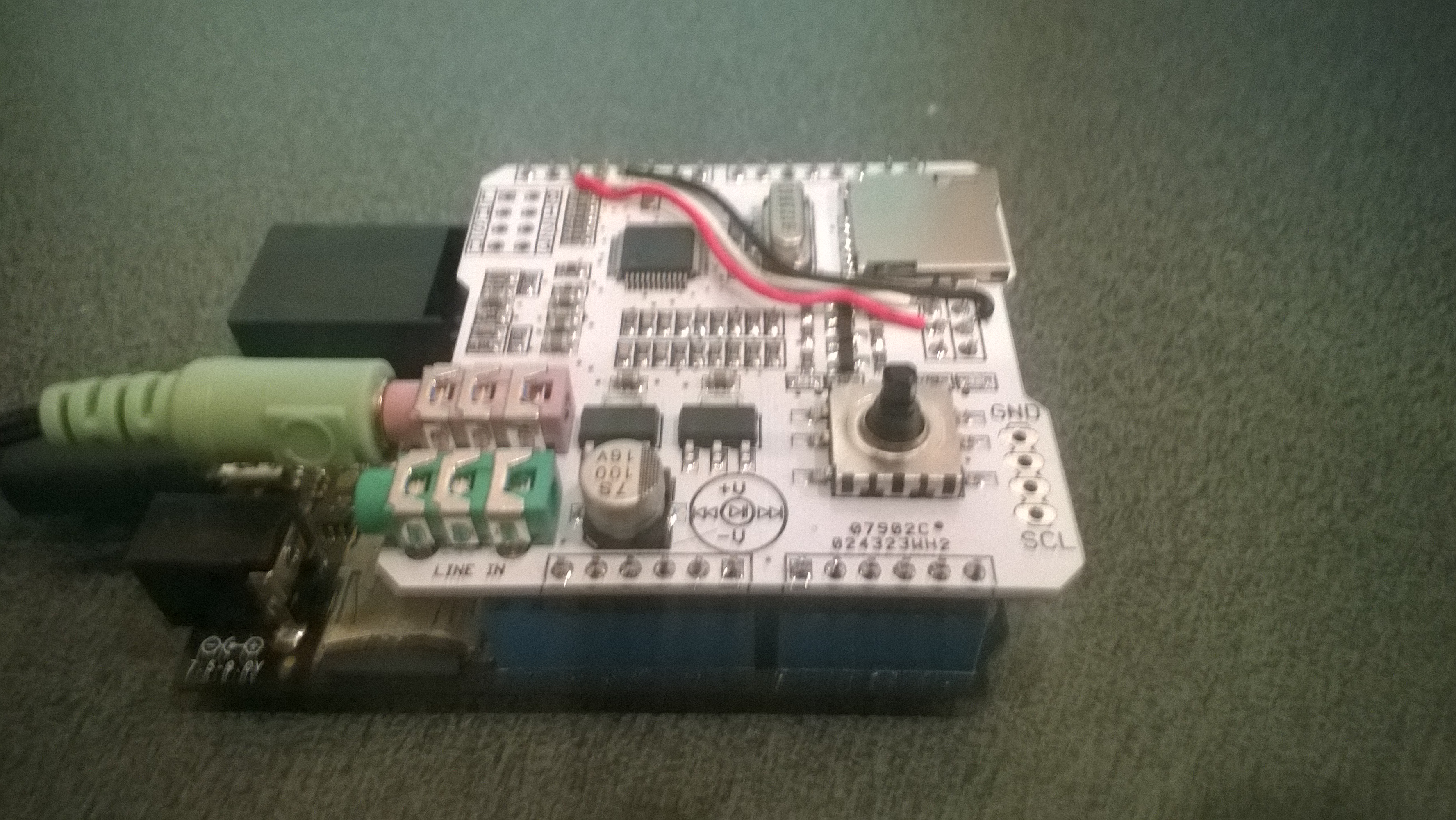
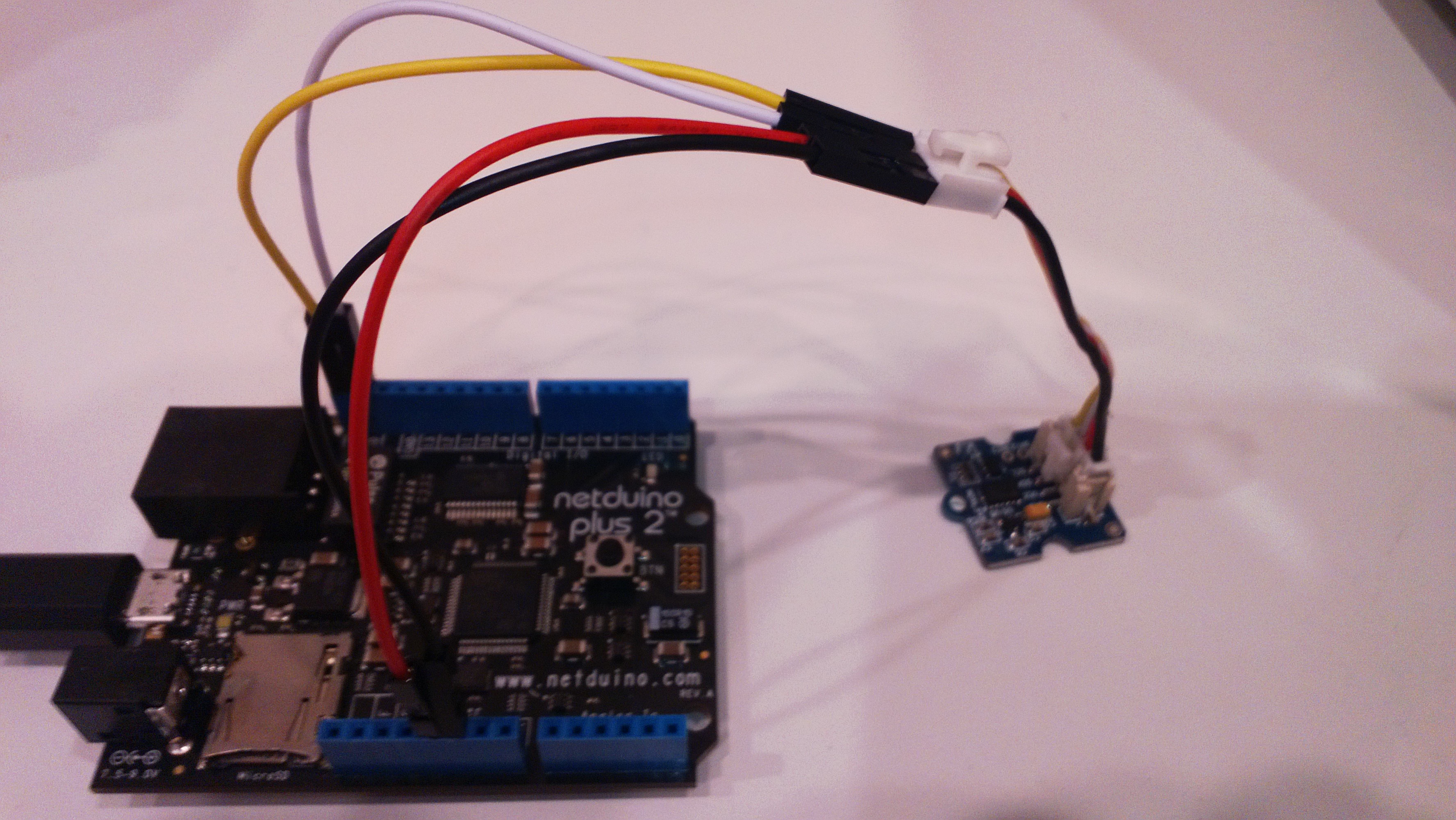
Netduino with Grove EMG Detector
The EMG detector outputs a single analog signal which we connected to analog input 0. For the proof of concept we averaged for 500 samples to determine the steady state offset.
for (int sampleCounter = 0; sampleCounter < calibrationSampleCount; sampleCounter++)
{
   double value = emg.Read();
   sampleSum += value;
}
offset = sampleSum / calibrationSampleCount ;
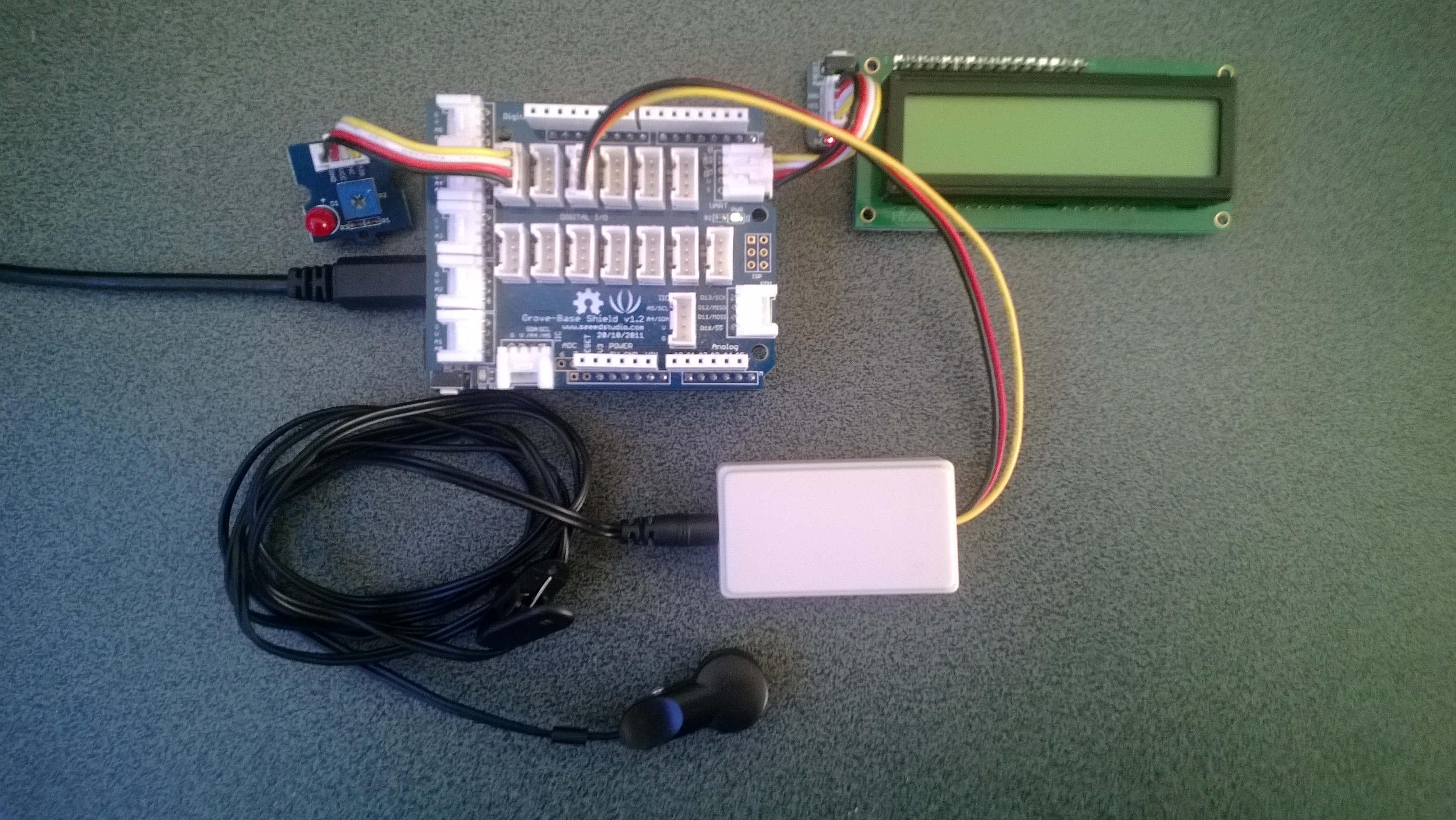
We then read the analog input applied the offset and displayed the magnitude of the signal on a Seeedstudio LED bar using code written by Famoury Toure
while(true)
{
   double value = emg.Read() - offset;

   if (value < valueMinimum) { valueMinimum = value; } if (value > valueMaximum)
   {
      valueMaximum = value;
   }
   range = valueMaximum - valueMinimum;

   if (value < 0)
   {
      value = value / valueMaximum * 10.0;
   }
   else
   {
      value = value / valueMinimum * 10.0;
   }

   Debug.Print("Val " + value.ToString("F3") + " Max " + valueMaximum.ToString("F3") + " Min " +valueMinimum.ToString("F3"));

   int bar = 1;
   value = 10.0 - value;
   bar = bar << (int)value ;
   ledBar.setLED((uint)bar);
   Thread.Sleep(100);
   }
}
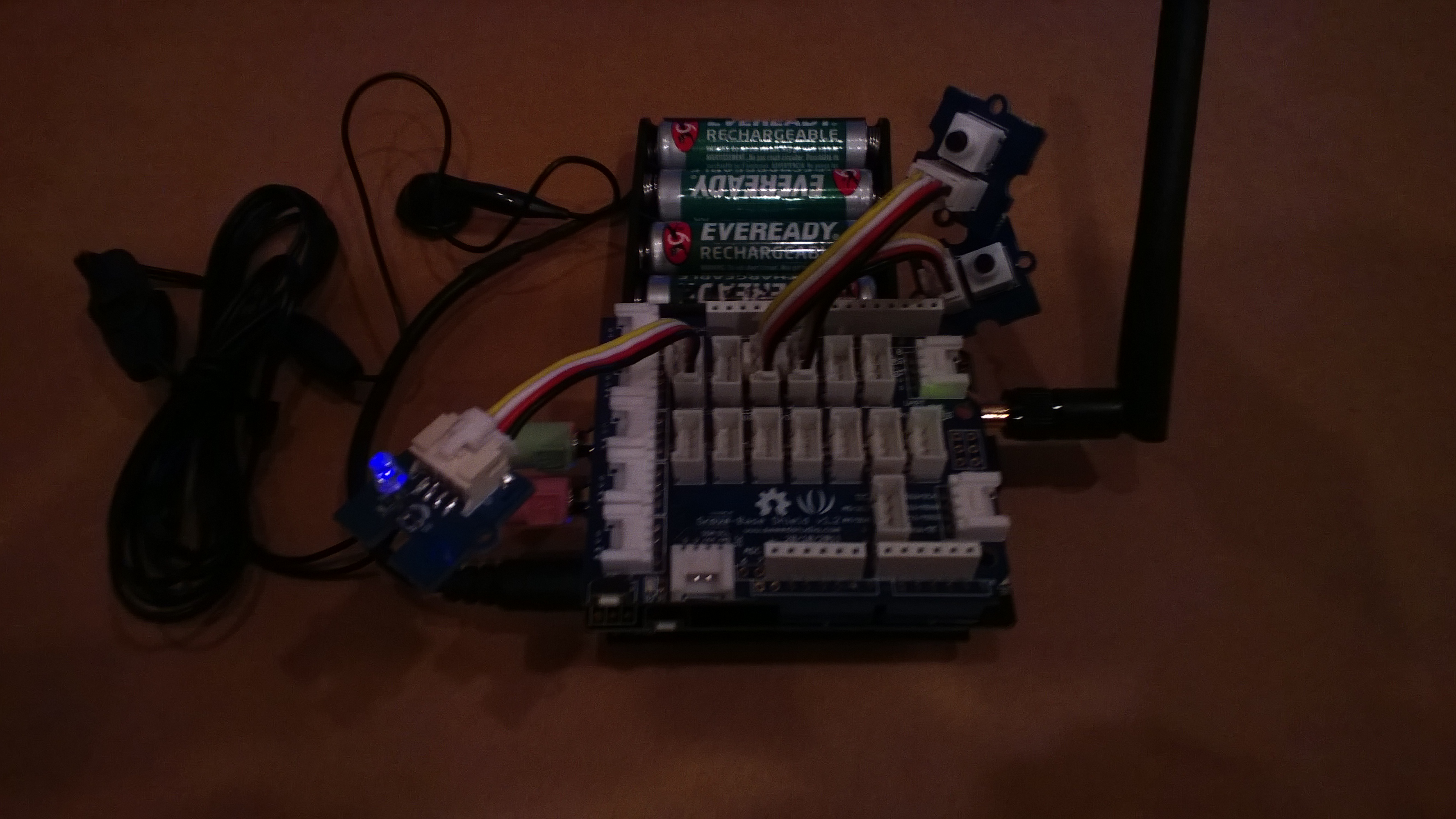
Bill of Materials (Prices as at October 2014)
- 2 x Netduino Plus 2 USD60,NZD108 or Netduino 2 USD33,NZD60
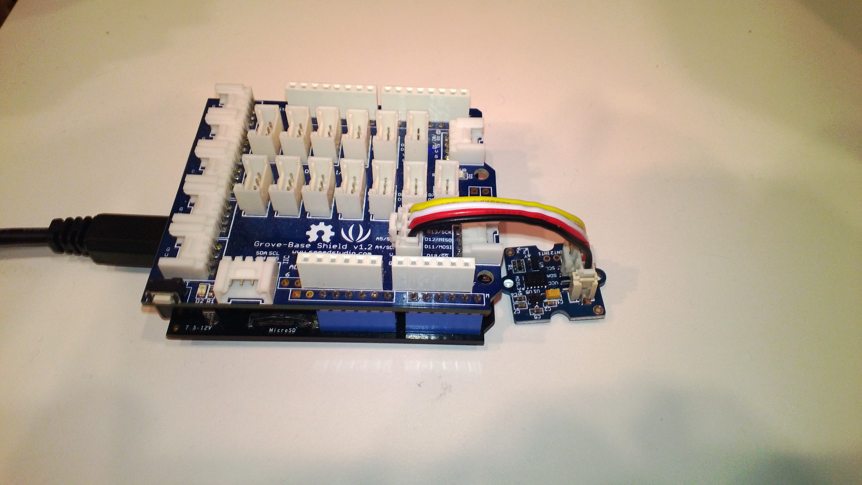
- 1 x Grove Base Shield V2 USD8.90
- 1 x Grove LED bar USD3.90
- 1 x Grove EMG Detector USD48
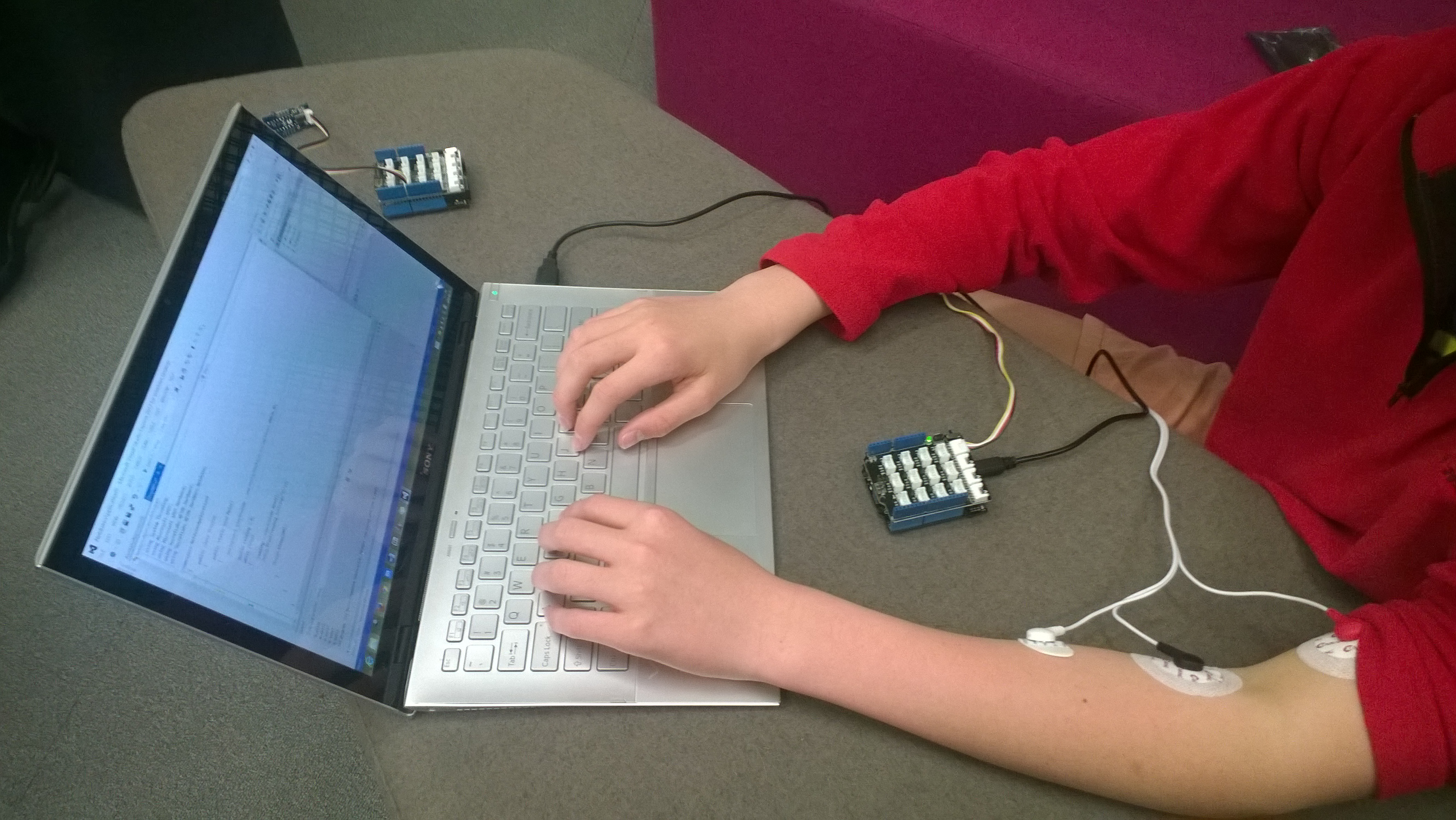
The proof of concept worked surprisingly well, the LED illuminated on the LED bar appeared to move in response to arm movements and when I clenched my fist.