As part of this series of samples comparing Arduino to nanoFramework to .NET IoT Device “Proof of Concept (PoC) applications, several posts use a SenseCap Industrial Light Intensity Sensor (SKU314990739 or SKU 314990740)
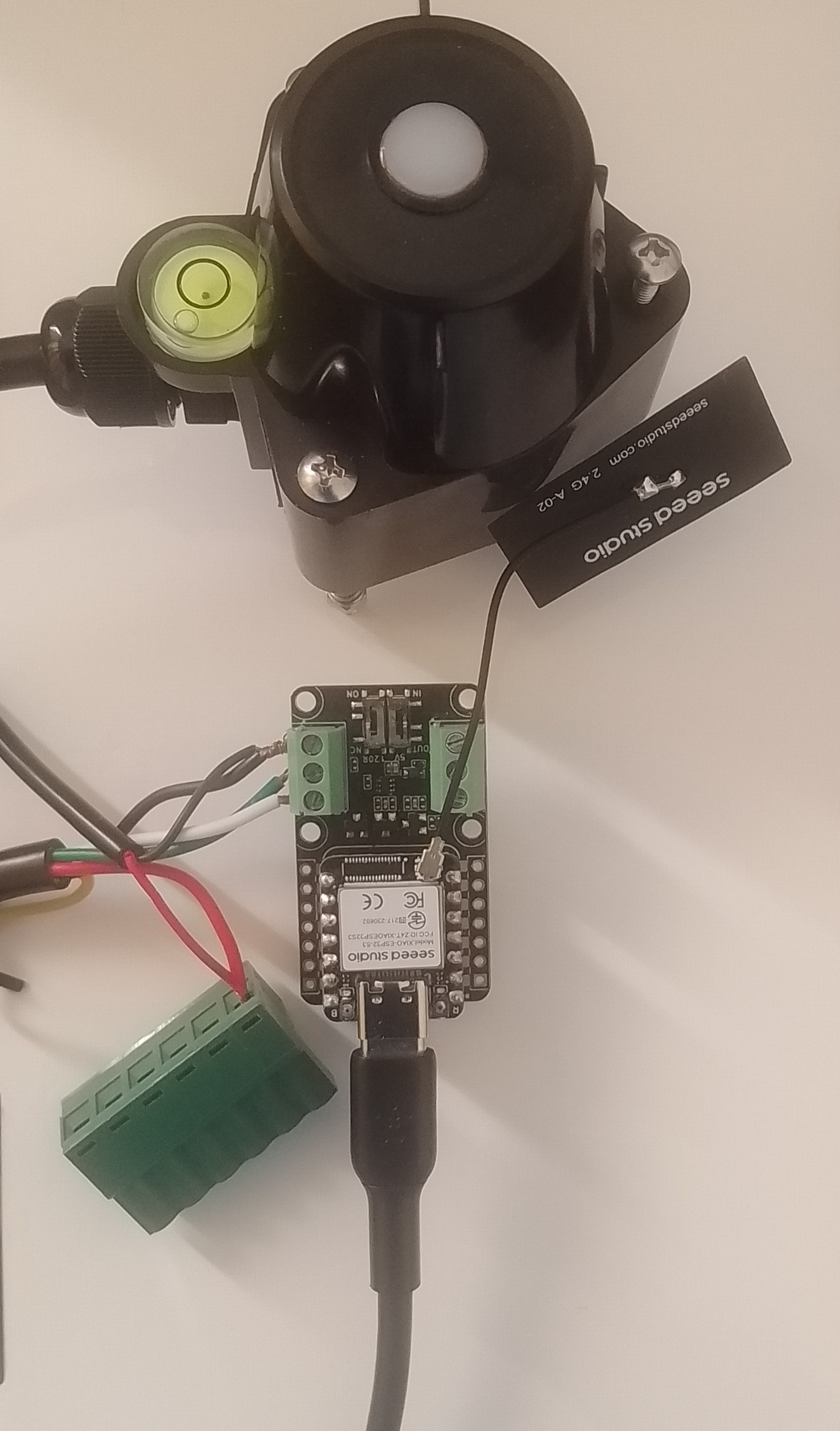
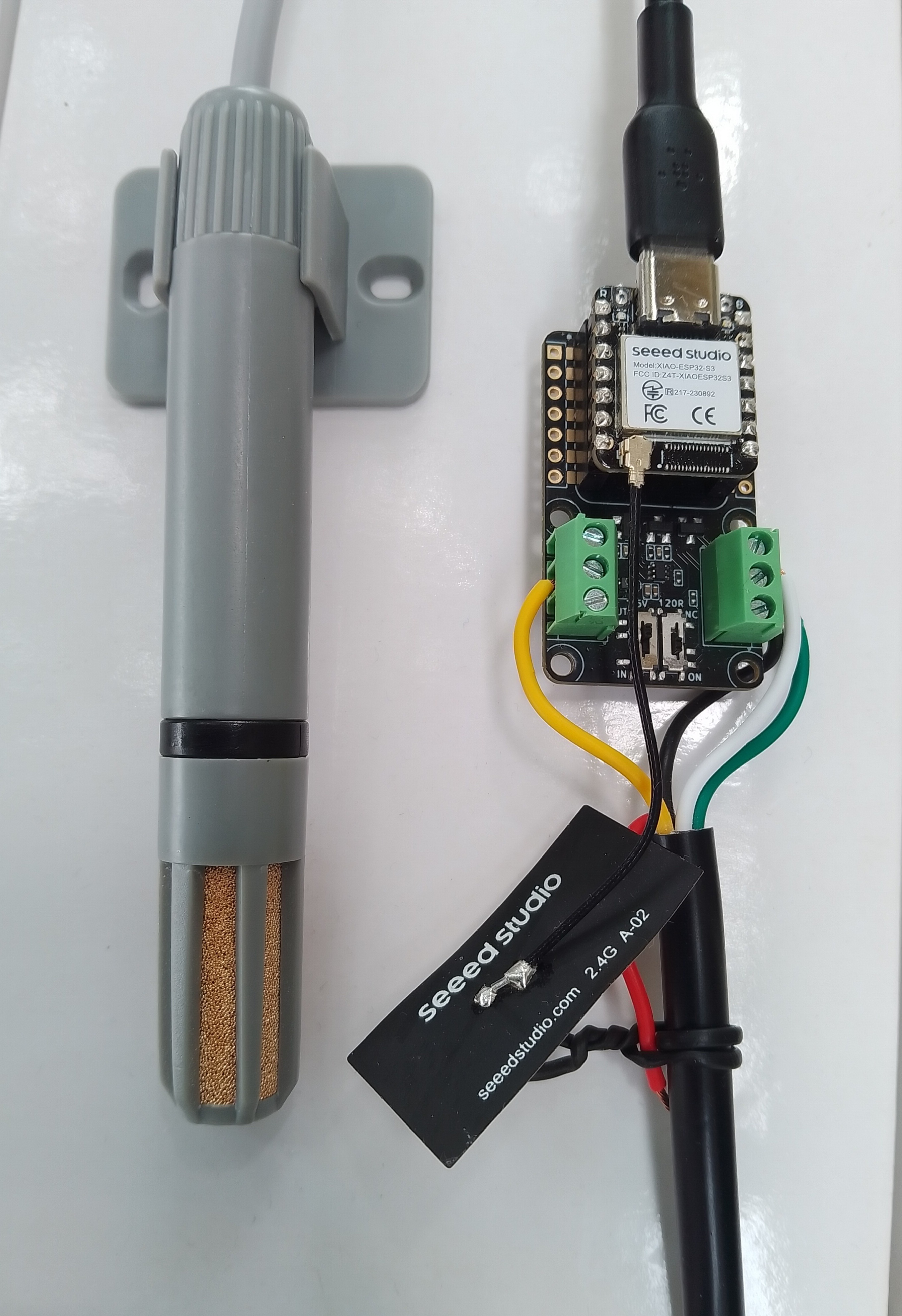
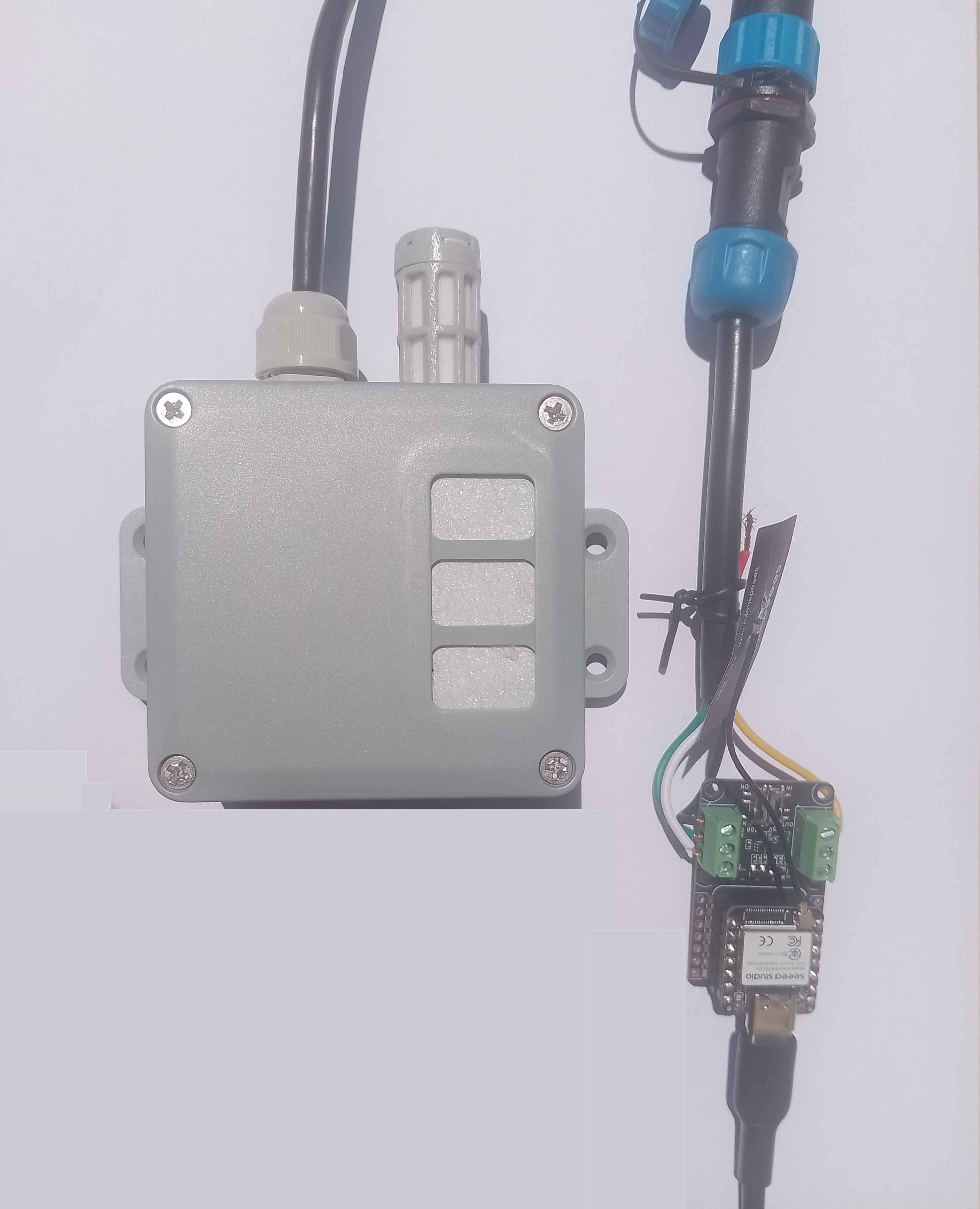
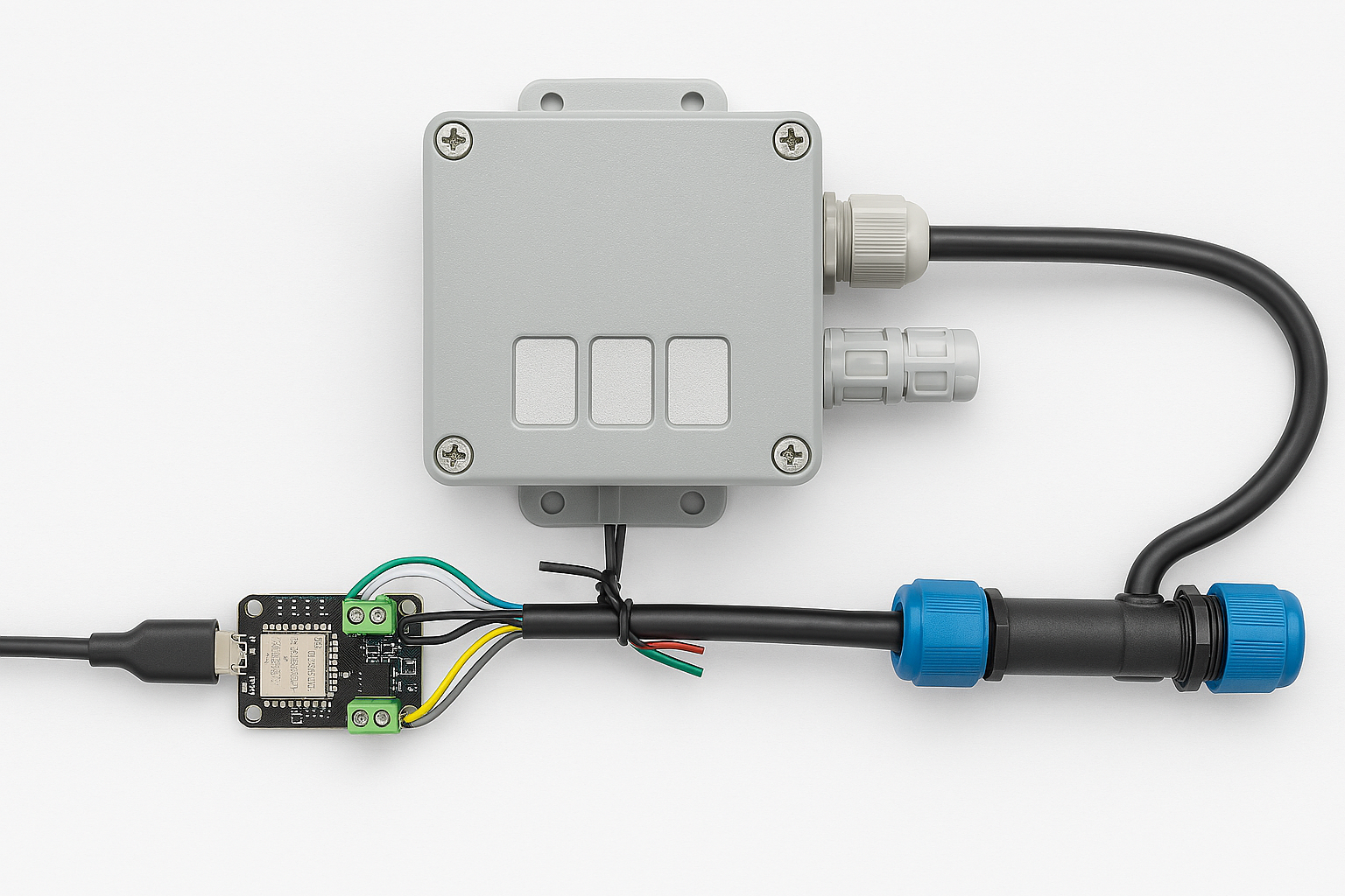
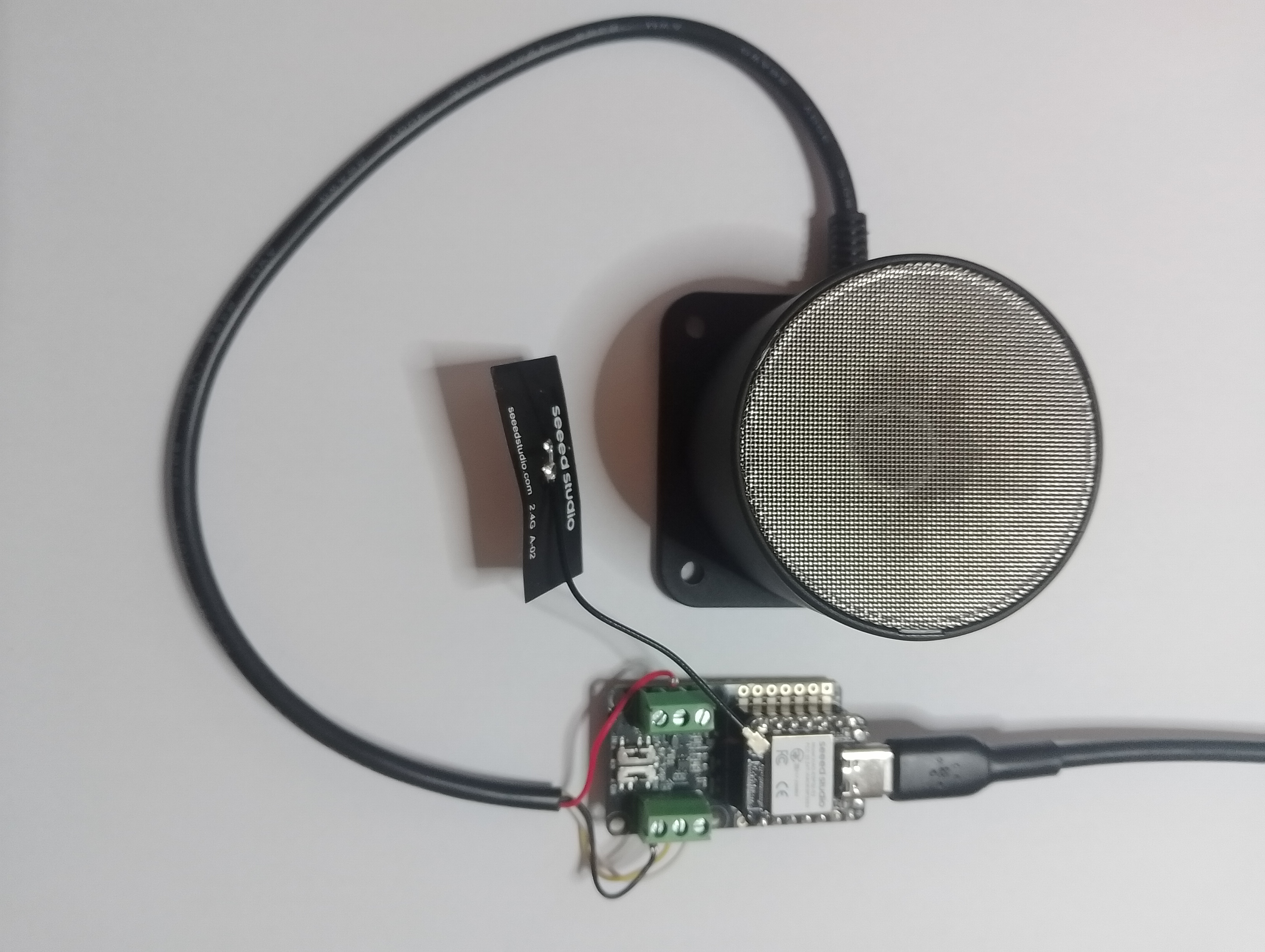
I cut one of the cables of a spare Industrial IP68 Modbus RS485 1-to-4 Splitter/Hub to connect the sensor to the RS485 breakout board.
The sensor has an operating voltage of 3.6-30V but it is connected to the 12V supply pin. Initially, I had the sensor connected to the 5V output of the RS485 Breakout Board for Seeed Studio XIAO (SKU 113991354) so it didn’t work.
// Modbus Client
using (var _client = new ModbusClient("COM2"))
{
#if DEBUG_LOGGER
_client.Logger = new DebugLogger("ModbusClient")
{
MinLogLevel = LogLevel.Debug
};
#endif
while (true)
{
try
{
// regs[0] = High order byye of value.
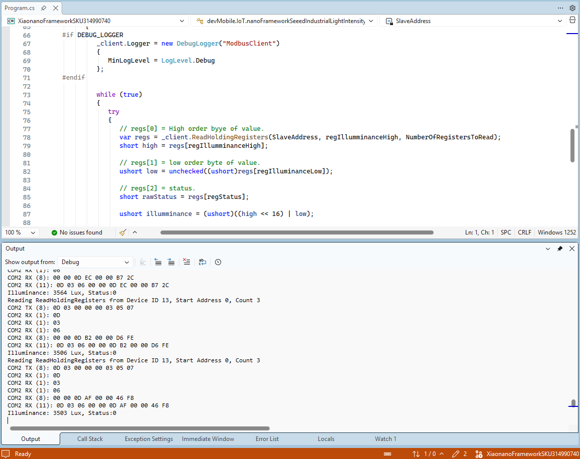
var regs = _client.ReadHoldingRegisters(SlaveAddress, regIllumminanceHigh, NumberOfRegistersToRead);
short high = regs[regIllumminanceHigh];
// regs[1] = low order byte of value.
ushort low = unchecked((ushort)regs[regIlluminanceLow]);
// regs[2] = status.
short rawStatus = regs[regStatus];
ushort illumminance = (ushort)((high << 16) | low);
Console.WriteLine($"Illuminance: {illumminance} Lux, Status:{rawStatus}");
}
catch (Exception ex)
{
Console.WriteLine($"Read failed: {ex.Message}");
}
Thread.Sleep(60000);
}
}
For the next version the “status” value will be mapped to an enumeration.