When developing libraries it’s good to have a selection of different platforms for testing as this can significantly improve the quality and robustness of the implementation. A few months ago I noticed that RAK Wireless have a UWB Module Decawave DW1000 Wisblock so I added one to an order.
My second Qorvo DW1000 setup is a RAK120000 Wisblock Core module, on a RAK19007 WisBlock Base with a RAK13801 WisBlock Wireless module

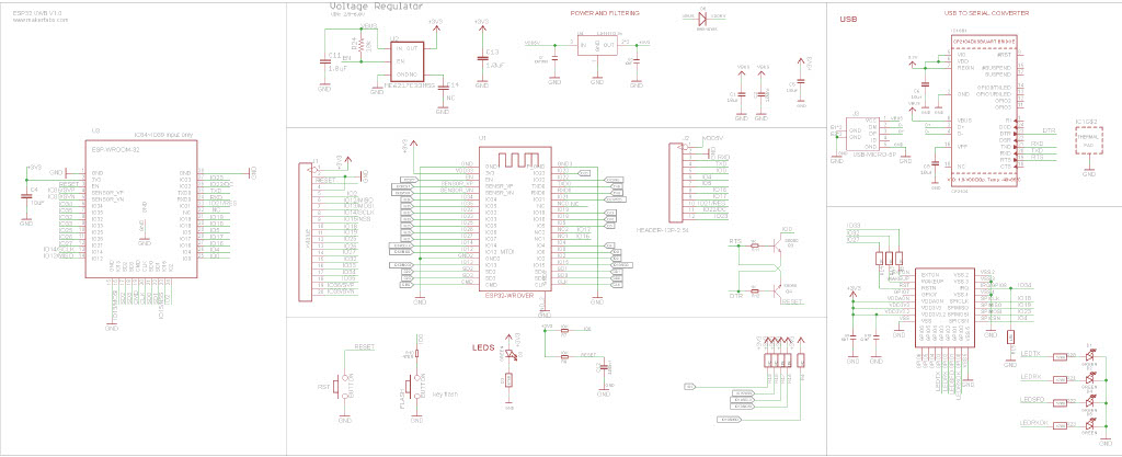
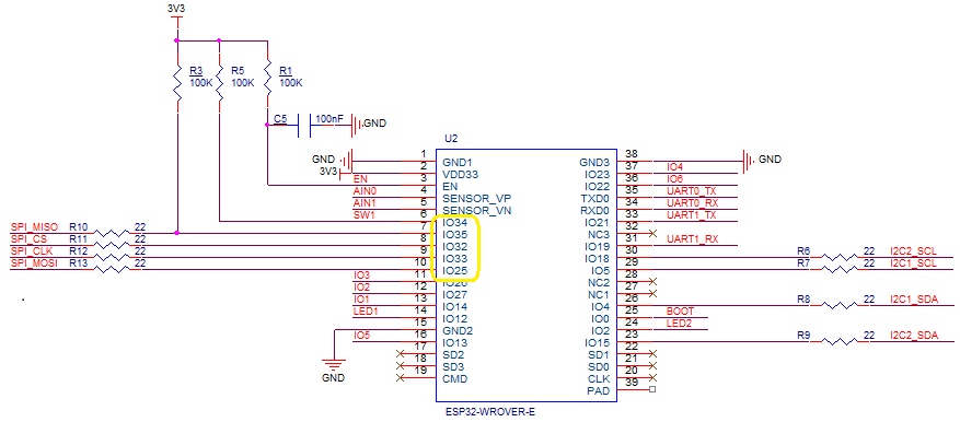
The Qorvo DW1000 module has a Serial Peripheral Interface (SPI) so the Master In Slave Out(MISO), Master Out Slave In(MOSI), Serial Clock(SCLK) and Chip Slave Select(CSS) pins of the RAK11200 WisBiock Core Module have to be setup using the Configuration.SetPinFunction method of the nanoFramework.Hardware.Esp32 library.

I have added a couple of C# processor directives (MAKERFABS_ESP32UWB & RAK11200_RAK1907_RAK13801) so the platform that the Qorvo DW1000 module is running on can be configured.
public class Program
{
#if MAKERFABS_ESP32UWB
private const int SpiBusId = 1;
private const int chipSelectLine = Gpio.IO04;
#endif
#if RAK11200_RAK1907_RAK13801
private const int SpiBusId = 1;
private const int chipSelectLine = Gpio.IO32;
#endif
public static void Main()
{
Thread.Sleep(5000);
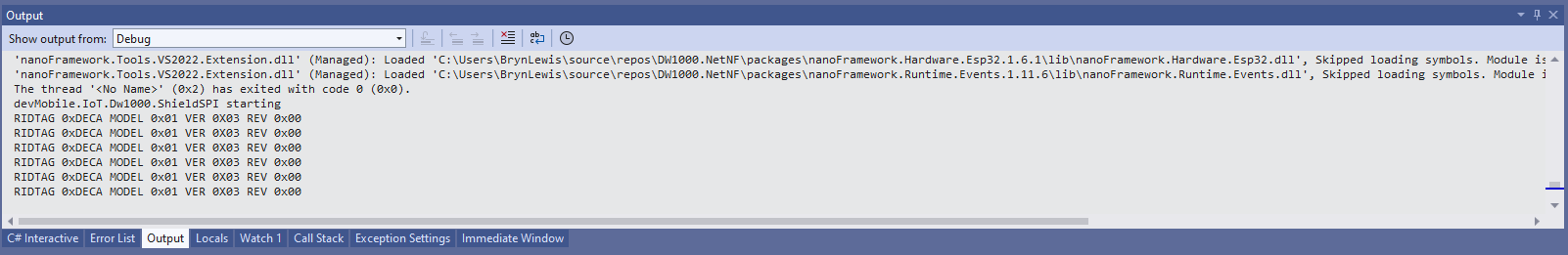
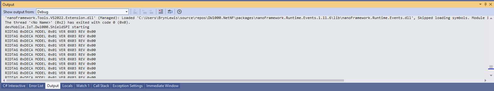
Debug.WriteLine("devMobile.IoT.Dw1000.ShieldSPI starting");
try
{
#if MAKERFABS_ESP32UWB
Configuration.SetPinFunction(Gpio.IO19, DeviceFunction.SPI1_MISO);
Configuration.SetPinFunction(Gpio.IO23, DeviceFunction.SPI1_MOSI);
Configuration.SetPinFunction(Gpio.IO18, DeviceFunction.SPI1_CLOCK);
#endif
#if RAK11200_RAK1907_RAK13801
Configuration.SetPinFunction(Gpio.IO35, DeviceFunction.SPI1_MISO);
Configuration.SetPinFunction(Gpio.IO25, DeviceFunction.SPI1_MOSI);
Configuration.SetPinFunction(Gpio.IO33, DeviceFunction.SPI1_CLOCK);
#endif
var settings = new SpiConnectionSettings(SpiBusId, chipSelectLine)
{
ClockFrequency = 2000000,
Mode = SpiMode.Mode0,
};
using (SpiDevice device = SpiDevice.Create(settings))
{
while (true)
{
byte[] writeBuffer = new byte[] { 0x0, 0x0, 0x0, 0x0, 0x0 }; // 0x0 = DEV_ID
byte[] readBuffer = new byte[writeBuffer.Length];
device.TransferFullDuplex(writeBuffer, readBuffer); // 15, 48, 1, 202, 222
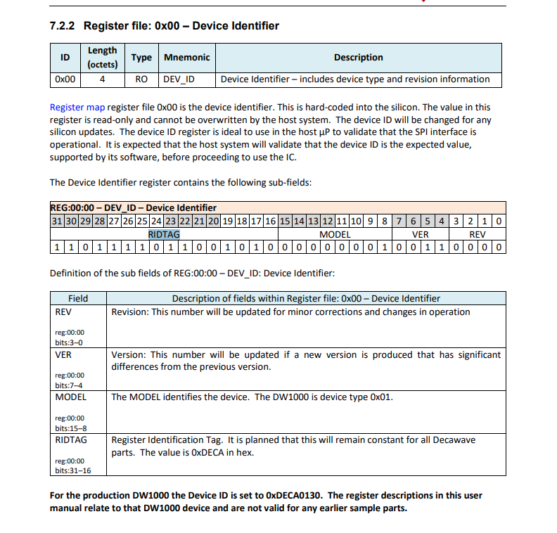
uint ridTag = (uint)(readBuffer[4]<< 8 | readBuffer[3]);
byte model = readBuffer[2];
byte ver = (byte)(readBuffer[1] >> 4);
byte rev = (byte)(readBuffer[1] & 0x0f);
Debug.WriteLine(String.Format($"RIDTAG 0x{ridTag:X2} MODEL 0x{model:X2} VER 0X{ver:X2} REV 0x{rev:X2}"));
Thread.Sleep(10000);
}
}
}
catch (Exception ex)
{
Debug.WriteLine(ex.Message);
}
}
}
The alignment of the RAK11200 WisBiock Core Module pins and labels on the circuit diagram tripped me up. My initial configuration caused the device to reboot every time the application started.
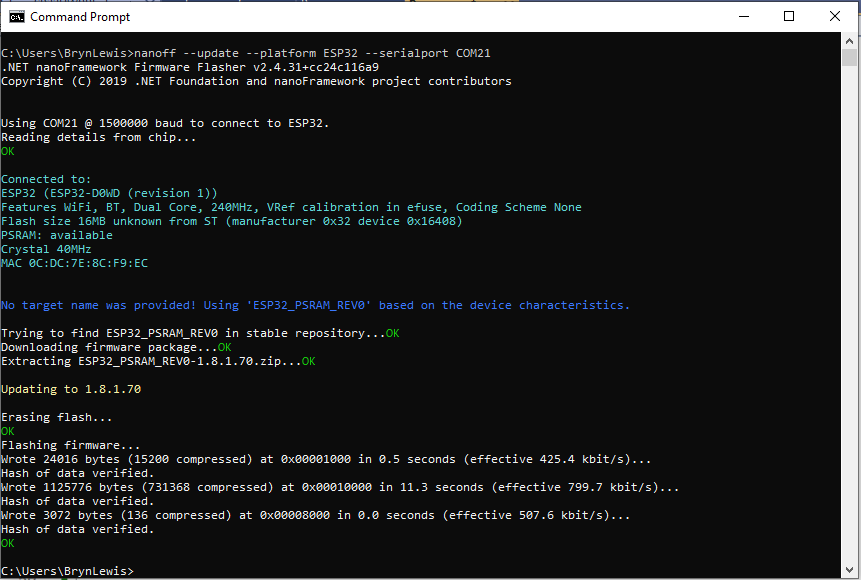
At the top of test applications, I usually have a brief delay i.e Thread.Sleep(5000) so I can attach the debugger or erase the flash before the application crashes.