Random wanderings through Microsoft Azure esp. PaaS plumbing, the IoT bits, AI on Micro controllers, AI on Edge Devices, .NET nanoFramework, .NET Core on *nix and ML.NET+ONNX
In this version a downlink message can be sent to a device only after an uplink message. I’m looking at adding an Azure Function which initiates a connection to the configured Azure IoT Hub for the specified device to mitigate with this issue.
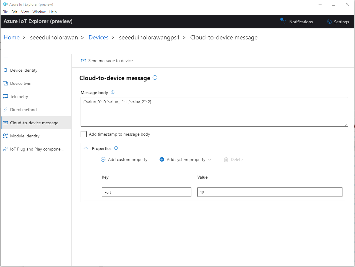
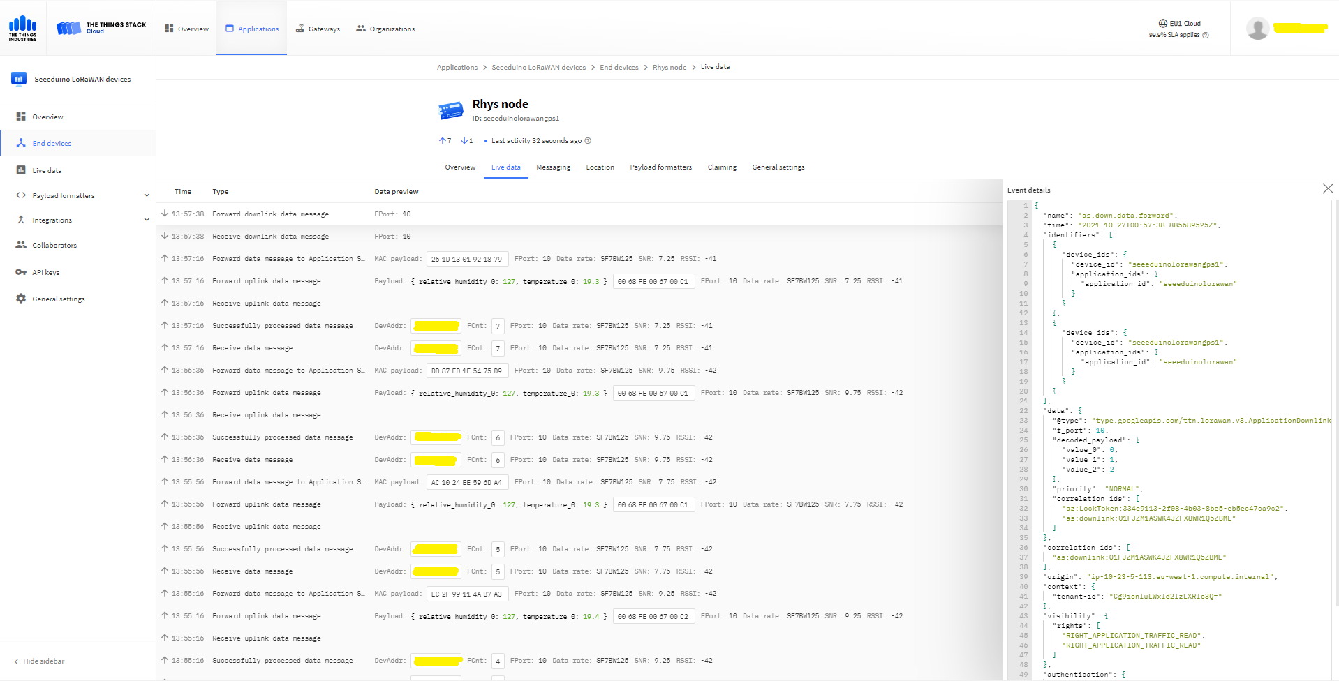
To send a TTN downlink message to a device the minimum required info is the LoRaWAN port number (specified in a Custom Property on the Azure IoT Hub cloud to device message), the device Id (from uplink message payload, which has been validated by a successful Azure IoT Hub connection) web hook id, web hook base URL, and an API Key (The Web Hook parameters are stored in the Connector configuration).
After some experimentation in previous TTN Connectors I found the synchronous nature of DirectMethods didn’t work well with LoRAWAN “irregular” connectivity so currently they are ignored.
public partial class Integration
{
	private async Task AzureIoTHubClientReceiveMessageHandler(Message message, object userContext)
	{
		try
		{
			Models.AzureIoTHubReceiveMessageHandlerContext receiveMessageHandlerContext = (Models.AzureIoTHubReceiveMessageHandlerContext)userContext;

			if (!_DeviceClients.TryGetValue(receiveMessageHandlerContext.DeviceId, out DeviceClient deviceClient))
			{
				_logger.LogWarning("Downlink-DeviceID:{0} unknown", receiveMessageHandlerContext.DeviceId);
				return;
			}

			using (message)
			{
				string payloadText = Encoding.UTF8.GetString(message.GetBytes()).Trim();

				if (!AzureDownlinkMessage.PortTryGet(message.Properties, out byte port))
				{
					_logger.LogWarning("Downlink-Port property is invalid");

					await deviceClient.RejectAsync(message);
					return;
				}

				// Split over multiple lines in an attempt to improve readability. In this scenario a valid JSON string should start/end with {/} for an object or [/] for an array
				if ((payloadText.StartsWith("{") && payloadText.EndsWith("}"))
														||
					((payloadText.StartsWith("[") && payloadText.EndsWith("]"))))
				{
					try
					{
						downlink.PayloadDecoded = JToken.Parse(payloadText);
					}
					catch (JsonReaderException)
					{
						downlink.PayloadRaw = payloadText;
					}
				}
				else
				{
					downlink.PayloadRaw = payloadText;
				}

				_logger.LogInformation("Downlink-IoT Hub DeviceID:{0} MessageID:{1} LockToken :{2} Port{3}",
					receiveMessageHandlerContext.DeviceId,
					message.MessageId,
		            message.LockToken,
					downlink.Port);

				Models.DownlinkPayload Payload = new Models.DownlinkPayload()
				{
					Downlinks = new List<Models.Downlink>()
					{
						downlink
					}
				};

				string url = $"{receiveMessageHandlerContext.WebhookBaseURL}/{receiveMessageHandlerContext.ApplicationId}/webhooks/{receiveMessageHandlerContext.WebhookId}/devices/{receiveMessageHandlerContext.DeviceId}/down/replace");

				using (var client = new WebClient())
				{
					client.Headers.Add("Authorization", $"Bearer {receiveMessageHandlerContext.ApiKey}");

					client.UploadString(new Uri(url), JsonConvert.SerializeObject(Payload));
				}

				_logger.LogInformation("Downlink-DeviceID:{0} LockToken:{1} success", receiveMessageHandlerContext.DeviceId, message.LockToken);
			}
		}
		catch (Exception ex)
		{
			_logger.LogError(ex, "Downlink-ReceiveMessge processing failed");
		}
	}
}
I have included sample application in the Github repository to show how to use the library
namespace devMobile.IoT.NetCore.Sensirion
{
	using System;
	using System.Device.I2c;
	using System.Threading;

	class Program
	{
		static void Main(string[] args)
		{
			// bus id on the raspberry pi 3
			const int busId = 1;

			I2cConnectionSettings i2cConnectionSettings = new(busId, Sht20.DefaultI2cAddress);

			using I2cDevice i2cDevice = I2cDevice.Create(i2cConnectionSettings);

			using (Sht20 sht20 = new Sht20(i2cDevice))
			{
				sht20.Reset();

				while (true)
				{
					double temperature = sht20.Temperature();
					double humidity = sht20.Humidity();

#if HEATER_ON_OFF
					sht20.HeaterOn();
					Console.WriteLine($"{DateTime.Now:HH:mm:ss} HeaterOn:{sht20.IsHeaterOn()}");
#endif
					Console.WriteLine($"{DateTime.Now:HH:mm:ss} Temperature:{temperature:F1}°C Humidity:{humidity:F0}% HeaterOn:{sht20.IsHeaterOn()}");
#if HEATER_ON_OFF
					sht20.HeaterOff();
					Console.WriteLine($"{DateTime.Now:HH:mm:ss} HeaterOn:{sht20.IsHeaterOn()}");
#endif

					Thread.Sleep(1000);
				}
			}
		}
	}
}
The Sensiron SHT20 has a heater which is intended to be used for functionality diagnosis – relative humidity drops upon rising temperature. The heater consumes about 5.5mW and provides a temperature increase of about 0.5 – 1.5°C.
Beware when the device is soft reset the heater bit is not cleared.
I have included sample application to show how to use the library
namespace devMobile.IoT.NetCore.GroveBaseHat
{
	using System;
	using System.Device.I2c;
	using System.Threading;

	class Program
	{
		static void Main(string[] args)
		{
			// bus id on the raspberry pi 3
			const int busId = 1;

			I2cConnectionSettings i2cConnectionSettings = new(busId, AnalogPorts.DefaultI2cAddress);

			using (I2cDevice i2cDevice = I2cDevice.Create(i2cConnectionSettings))
			using (AnalogPorts AnalogPorts = new AnalogPorts(i2cDevice))
			{
				Console.WriteLine($"{DateTime.Now:HH:mm:SS} Version:{AnalogPorts.Version()}");
				Console.WriteLine();

				double powerSupplyVoltage = AnalogPorts.PowerSupplyVoltage();
				Console.WriteLine($"{DateTime.Now:HH:mm:SS} Power Supply Voltage:{powerSupplyVoltage:F2}v");

				while (true)
				{
					double value = AnalogPorts.Read(AnalogPorts.AnalogPort.A0);
					double rawValue = AnalogPorts.ReadRaw(AnalogPorts.AnalogPort.A0);
					double voltageValue = AnalogPorts.ReadVoltage(AnalogPorts.AnalogPort.A0);

					Console.WriteLine($"{DateTime.Now:HH:mm:SS} Value:{value:F2} Raw:{rawValue:F2} Voltage:{voltageValue:F2}v");
					Console.WriteLine();

					Thread.Sleep(1000);
				}
			}
		}
	}
}
The GROVE_BASE_HAT_RPI and GROVE_BASE_HAT_RPI_ZERO are used to specify the number of available analog ports.
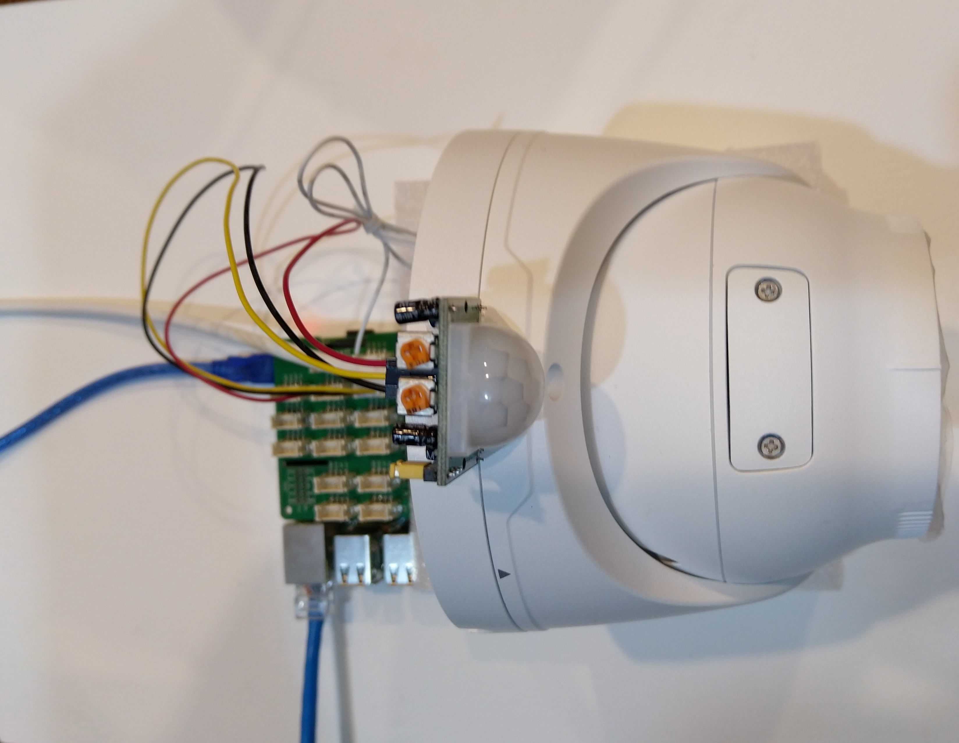
Uniview IPC3635SB-ADZK-I0 Security camera test rig with Raspberry PI and PIR motion detector
I tried to keep the .Net Core 5 console applications as simple as possible, they download an image from the camera “snapshot” endpoint (In this case http://10.0.0.47:85/images/snapshot.jpg), save it to the local filesystem and then upload it.
The core of the two applications is the “upload” image method, which is called by a timer or GPIO pin EventHandler
private static async void ImageUpdateTimerCallback(object state)
{
CommandLineOptions options = (CommandLineOptions)state;
DateTime requestAtUtc = DateTime.UtcNow;
// Just incase - stop code being called while retrival of the photo already in progress
if (cameraBusy)
{
return;
}
cameraBusy = true;
Console.WriteLine($"{requestAtUtc:yy-MM-dd HH:mm:ss} Image up load start");
try
{
// First go and get the image file from the camera onto local file system
using (var client = new WebClient())
{
NetworkCredential networkCredential = new NetworkCredential()
{
UserName = options.UserName,
Password = options.Password
};
client.Credentials = networkCredential;
await client.DownloadFileTaskAsync(new Uri(options.CameraUrl), options.LocalFilename);
}
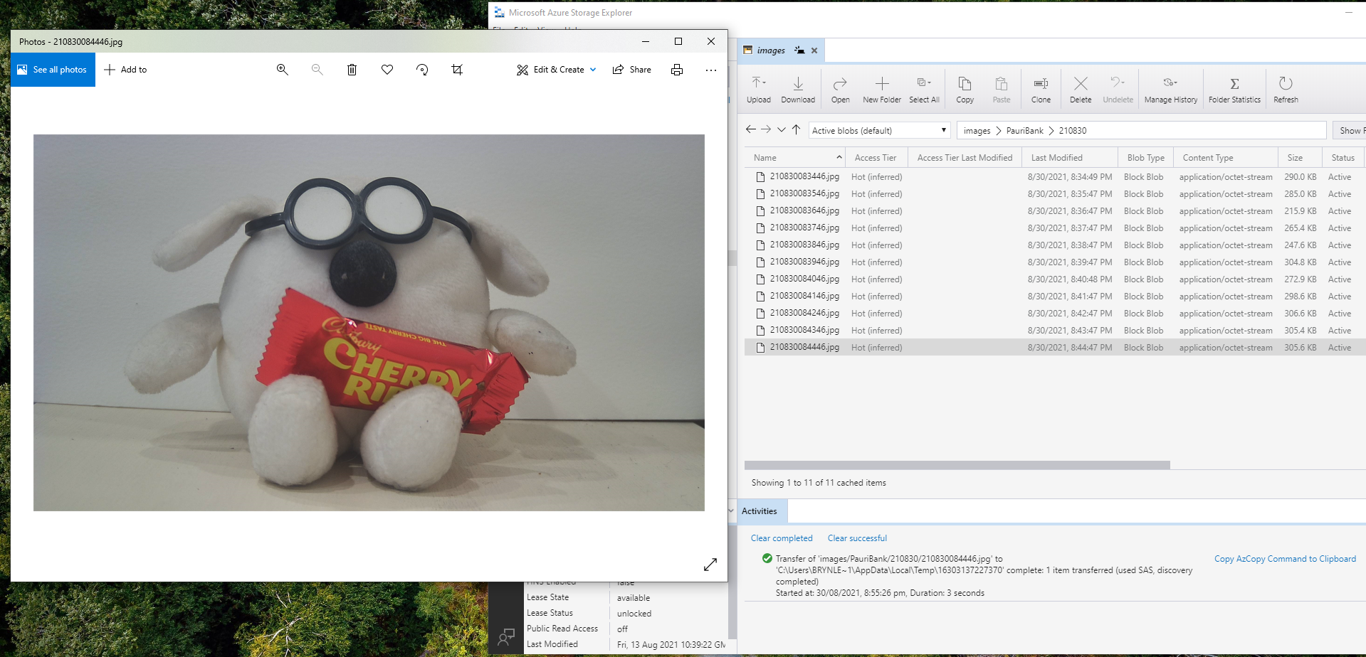
// Then open the file ready to stream ito upto storage account associated with Azuure IoT Hub
using (FileStream fileStreamSource = new FileStream(options.LocalFilename, FileMode.Open))
{
var fileUploadSasUriRequest = new FileUploadSasUriRequest
{
BlobName = string.Format("{0:yyMMdd}/{0:yyMMddHHmmss}.jpg", requestAtUtc)
};
// Get the plumbing sorted for where the file is going in Azure Storage
FileUploadSasUriResponse sasUri = await azureIoTCentralClient.GetFileUploadSasUriAsync(fileUploadSasUriRequest);
Uri uploadUri = sasUri.GetBlobUri();
try
{
var blockBlobClient = new BlockBlobClient(uploadUri);
var response = await blockBlobClient.UploadAsync(fileStreamSource, new BlobUploadOptions());
var successfulFileUploadCompletionNotification = new FileUploadCompletionNotification()
{
// Mandatory. Must be the same value as the correlation id returned in the sas uri response
CorrelationId = sasUri.CorrelationId,
// Mandatory. Will be present when service client receives this file upload notification
IsSuccess = true,
// Optional, user defined status code. Will be present when service client receives this file upload notification
StatusCode = 200,
// Optional, user-defined status description. Will be present when service client receives this file upload notification
StatusDescription = "Success"
};
await azureIoTCentralClient.CompleteFileUploadAsync(successfulFileUploadCompletionNotification);
}
catch (Exception ex)
{
Console.WriteLine($"Failed to upload file to Azure Storage using the Azure Storage SDK due to {ex}");
var failedFileUploadCompletionNotification = new FileUploadCompletionNotification
{
// Mandatory. Must be the same value as the correlation id returned in the sas uri response
CorrelationId = sasUri.CorrelationId,
// Mandatory. Will be present when service client receives this file upload notification
IsSuccess = false,
// Optional, user-defined status code. Will be present when service client receives this file upload notification
StatusCode = 500,
// Optional, user defined status description. Will be present when service client receives this file upload notification
StatusDescription = ex.Message
};
await azureIoTCentralClient.CompleteFileUploadAsync(failedFileUploadCompletionNotification);
}
}
TimeSpan uploadDuration = DateTime.UtcNow - requestAtUtc;
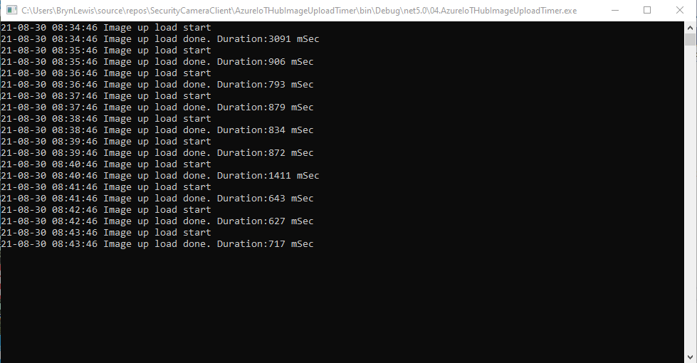
Console.WriteLine($"{requestAtUtc:yy-MM-dd HH:mm:ss} Image up load done. Duration:{uploadDuration.TotalMilliseconds:0.} mSec");
}
catch (Exception ex)
{
Console.WriteLine($"Camera image upload process failed {ex.Message}");
}
finally
{
cameraBusy = false;
}
}
The ONVIFspecification standardises the network interface (the network layer) of network video products. It defines a communication framework based on relevant IETF and Web Services standards including security and IP configuration requirements.
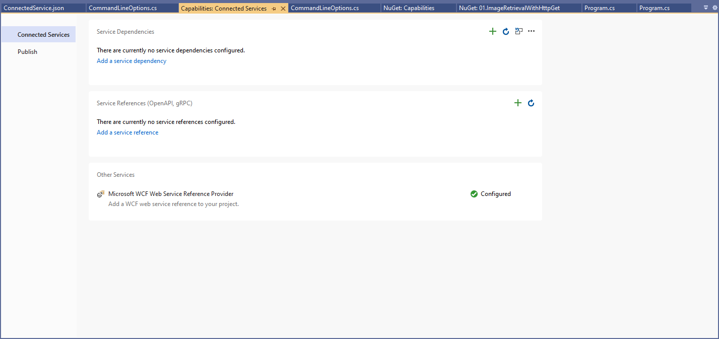
After discovering a device the next step was to query it to determine its capabilities. I had some issues with .Net Core 5 application configuring the Windows Communication Foundation(WCF) to use Digest authentication (RFC2617) credentials on all bar the device management service client.
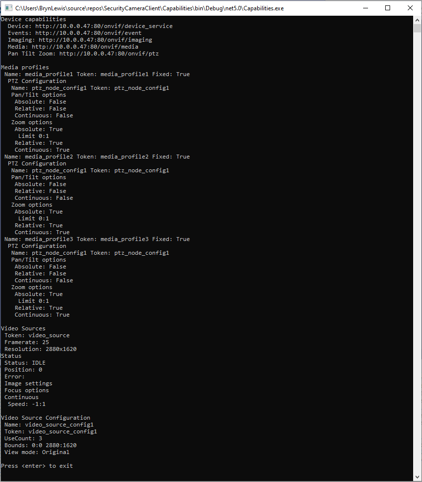
This .Net Core 5 console application queries the device management service (ONVID application programmers guide) to get the capabilities of the device then calls the media, imaging and pan tilt zoom services and displays the results.
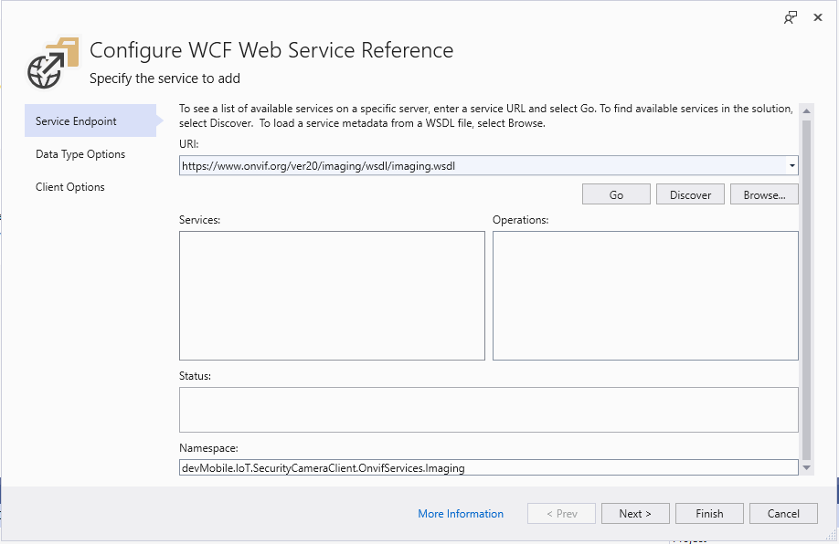
The Uniform Resource Locators(URL) and namespace prefixes for each generated service are configured in the ConnectedService.json file.
First step configuring a WCF Service
Initially I used a devMobile.IoT.SecurityCameraClient prefix but after some experimentation changed to OnvifServices.
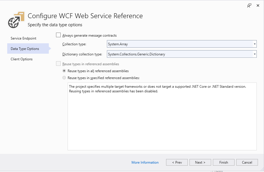
Second step configuring a WCF Service
For testing I selected “Generated Synchronous Operations” as they are easier to use in a console application while exploring the available functionality.
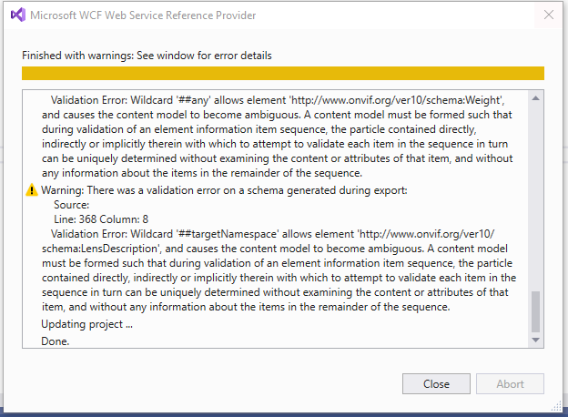
Third step configuring a WCF Service
The WSDL generated a number of warnings so I inspected the WSDL to see if the were easy to fix. I did consider copying the WSDL to my development box but it didn’t appear to be worth the effort.
SVCUtil warning messages about invalid Onvif WSDL
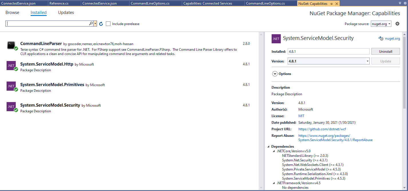
For this application I’m using the CommandLineParser NuGet package to parse and validate the client, username and password configured in the debugger tab.
Required Nuget packages
private static async Task ApplicationCore(CommandLineOptions options)
{
   Device deviceClient;
   ImagingPortClient imagingPortClient;
   MediaClient mediaClient;
   PTZClient panTiltZoomClient;

   var messageElement = new TextMessageEncodingBindingElement()
   {
      MessageVersion = MessageVersion.CreateVersion(EnvelopeVersion.Soap12, AddressingVersion.None),
      WriteEncoding = Encoding.UTF8
    };

    HttpTransportBindingElement httpTransportNoPassword = new HttpTransportBindingElement();
    CustomBinding bindingHttpNoPassword = new CustomBinding(messageElement, httpTransportNoPassword);

    HttpTransportBindingElement httpTransport = new HttpTransportBindingElement()
    {
       AuthenticationScheme = AuthenticationSchemes.Digest
    };
    CustomBinding bindingHttpPassword = new CustomBinding(messageElement, httpTransport);

    try
    {
       // Setup the imaging porting binding, use TLS, and ignore certificate errors
       deviceClient = new DeviceClient(bindingHttpNoPassword, new EndpointAddress($"http://{options.CameraUrl}/onvif/devicemgmt"));

       GetCapabilitiesResponse capabilitiesResponse = await deviceClient.GetCapabilitiesAsync(new GetCapabilitiesRequest(new CapabilityCategory[] { CapabilityCategory.All }));

       Console.WriteLine("Device capabilities");
       Console.WriteLine($"  Device: {capabilitiesResponse.Capabilities.Device.XAddr}");
       Console.WriteLine($"  Events: {capabilitiesResponse.Capabilities.Events.XAddr}"); // Not interested in events for V1
       Console.WriteLine($"  Imaging: {capabilitiesResponse.Capabilities.Imaging.XAddr}");
       Console.WriteLine($"  Media: {capabilitiesResponse.Capabilities.Media.XAddr}");
       Console.WriteLine($"  Pan Tilt Zoom: {capabilitiesResponse.Capabilities.PTZ.XAddr}");
       Console.WriteLine();
       ...
       Console.WriteLine($"Video Source Configuration");
       foreach (OnvifServices.Media.VideoSourceConfiguration videoSourceConfiguration in videoSourceConfigurations.Configurations)
      {
         Console.WriteLine($" Name: {videoSourceConfiguration.Name}");
         Console.WriteLine($" Token: {videoSourceConfiguration.token}");
         Console.WriteLine($" UseCount: {videoSourceConfiguration.UseCount}");
         Console.WriteLine($" Bounds: {videoSourceConfiguration.Bounds.x}:{videoSourceConfiguration.Bounds.y} {videoSourceConfiguration.Bounds.width}:{videoSourceConfiguration.Bounds.height}");
         Console.WriteLine($" View mode: {videoSourceConfiguration.ViewMode}");
      }
   }
   catch (Exception ex)
   {
      Console.WriteLine(ex.Message);
   }

   Console.WriteLine();
   Console.WriteLine("Press <enter> to exit");
   Console.ReadLine();
}
I had to do a bit of “null checking” as often if a feature wasn’t supported the root node was null. I need to get a selection of cameras (especially one with pan/tilt/zoom) to check that I’m processing the responses from the device correctly.
Console application output showing capabilities of Uniview device
After confirming the program was working on my development box I used the excellent RaspberryDebugger to download the application and run it on a Raspberry PI 3 running the Raspberry PI OS.
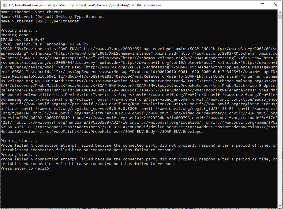
The ONVIFspecification standardises the network interface (the network layer) of network video products. It defines a communication framework based on relevant IETF and Web Services standards including security and IP configuration requirements. ONVIF uses Web Services Dynamic Discovery (WS-Discovery) to locate devices on the local network which operates over UDP port 3702 and uses IP multicast address 239.255.255.250.
My .Net Core 5 console application enumerates the host device’s network interfaces, then sends a “probe” message and waits for responses. The ONVID application programmers guide specifies the format of the “probe” request and response messages (One of the namespace prefixes in the sample is wrong). The client device can return its name and details of it’s capabilities in the response. Currently I only need the IP addresses of the cameras but if more information was required I would use the XML Serialisation functionality of .Net Core to generate the requests and unpack the responses.
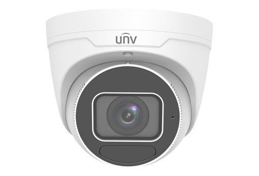
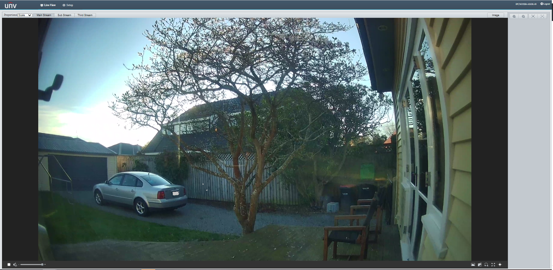
As part of a contract a customer sent me a UniviewIPC3635SB-ADZK-I0 Security camera for a proof of concept(PoC) project. Before the PoC I wanted to explore the camera functionality in more depth, especially how to retrieve individual images from the camera, remotely control it’s zoom, focus, pan, tilt etc.. I’m trying to source a couple of other vendors’ security cameras with remotely controllable pan and tilt for testing.
Uniview IPC3635SB-ADZK-I0 Security camera
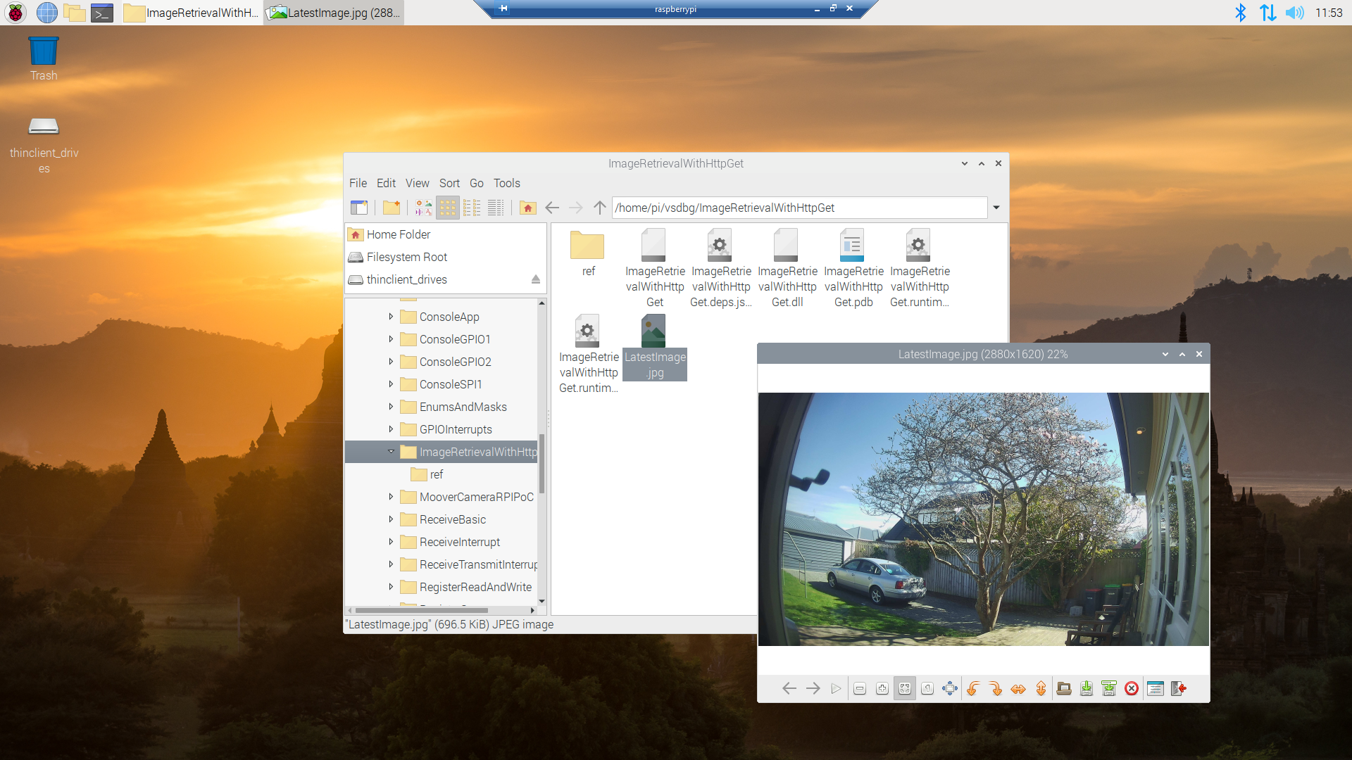
It appears that many cameras support retrieving the latest image with an HyperText Transfer Protocol (HTTP) GET so that looked like a good place to start. For the next couple of posts the camera will be sitting on the bookcase in my office looking through the window at the backyard.
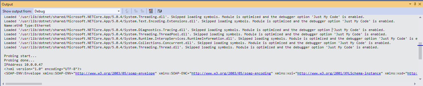
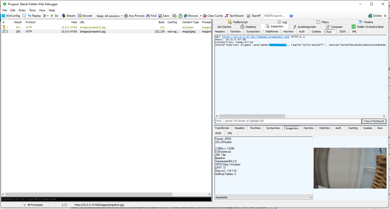
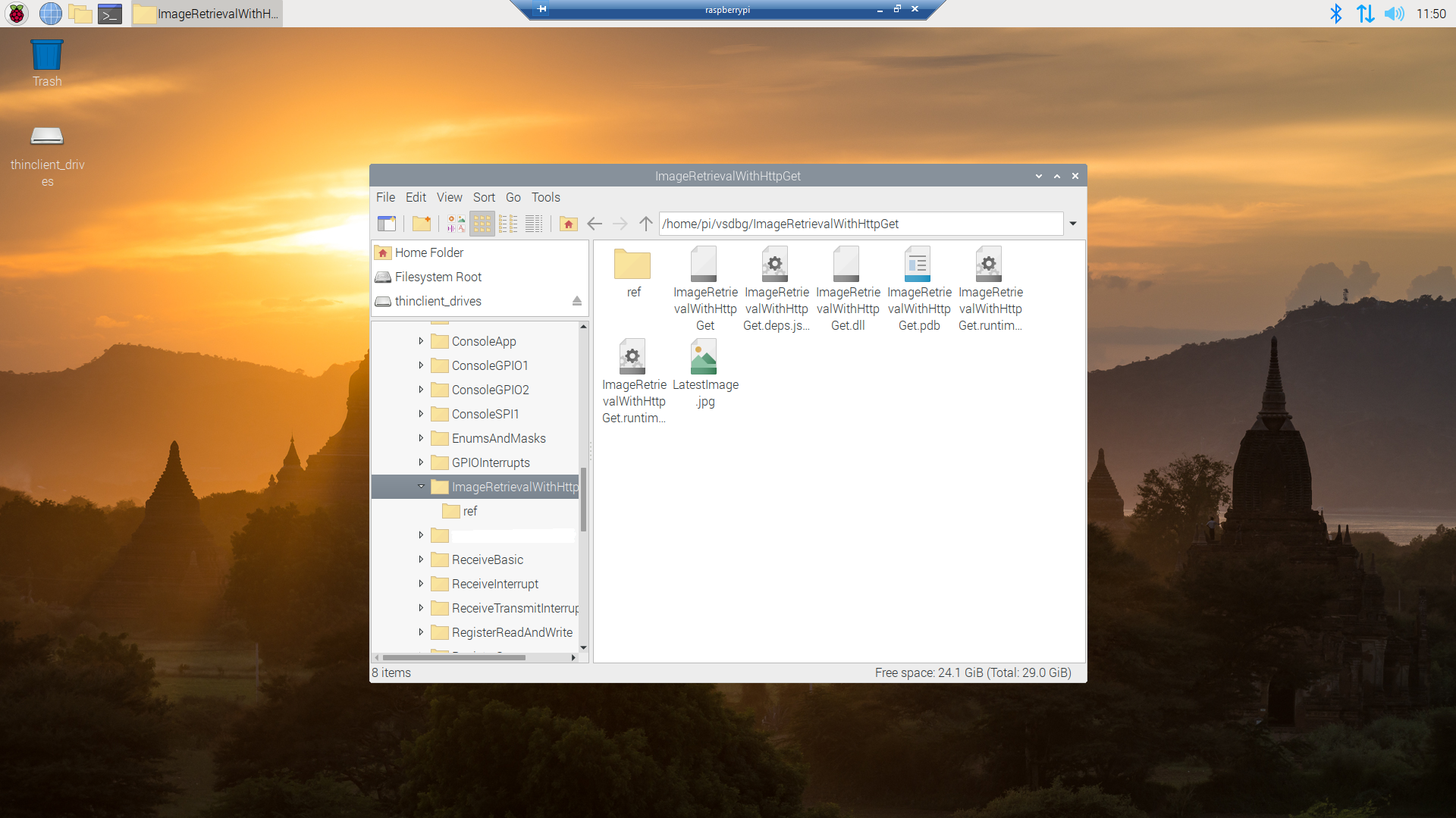
My .Net Core 5 console application is as simple possible, it just downloads an image from the camera “snapshot” endpoint (In this case http://10.0.0.47:85/images/snapshot.jpg) and saves it to the local filesystem.
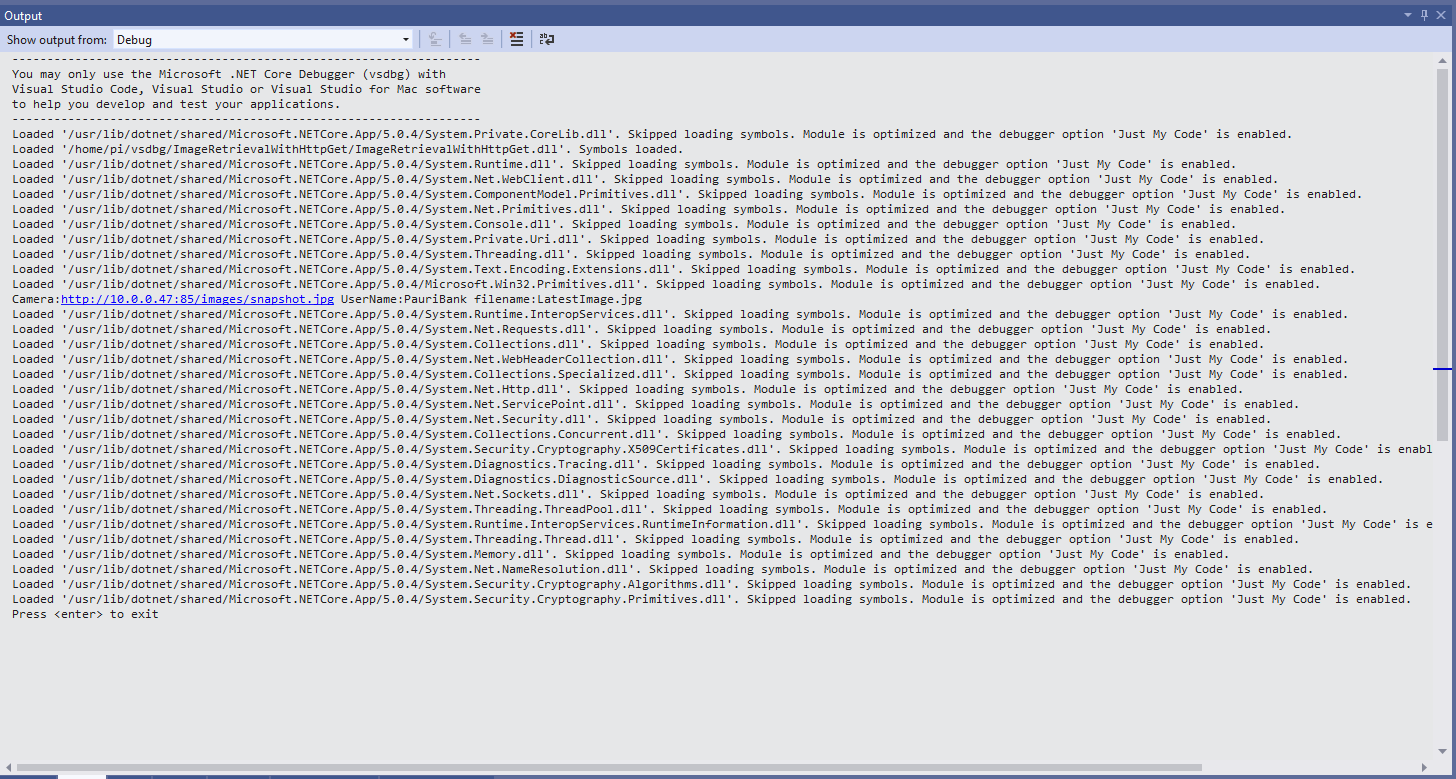
Visual Studio 2019 Debug Output showing application download process
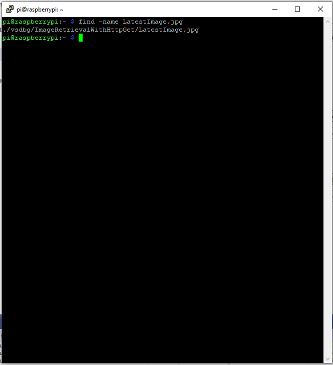
Once the application had finished running on the device I wanted to check that the file was on the local filesystem. I used Putty to connect to the Raspberry PI then searched for LatestImage.jpg.
Linux find utility displaying the location of the downloaded file
This post was about selecting the tooling I’m comfortable with and configuring my development environment so they work well together. The next step will be using Open Network Video Interface Forum (ONVIF) to discover, determine the capabilities of and then control the camera (for this device just zoom and focus).
The arduino-LoRa library LoRaDuplex sample is the basis for the last in this series of posts. The LoRaDuplex sample implements a basic protocol for addressed messages. The message payload starts with the destination address(byte), source address(byte), message counter(byte), payload length(byte), and then the payload(array of bytes).
LoRaDuplex
The sample code has configuration settings for the local address and destination (address).
#include <SPI.h>              // include libraries
#include <LoRa.h>

const int csPin = 10;          // LoRa radio chip select
const int resetPin = 9;       // LoRa radio reset
const int irqPin = 2;         // change for your board; must be a hardware interrupt pin

String outgoing;              // outgoing message

byte msgCount = 0;            // count of outgoing messages
byte localAddress = 0xAA;     // address of this device
byte destination = 0x0;      // destination to send to
long lastSendTime = 0;        // last send time
int interval = 2000;          // interval between sends

void setup() {
  Serial.begin(9600);                   // initialize serial
  while (!Serial);

  Serial.println("LoRa Duplex");

  // override the default CS, reset, and IRQ pins (optional)
  LoRa.setPins(csPin, resetPin, irqPin);// set CS, reset, IRQ pin

  if (!LoRa.begin(915E6)) {             // initialize ratio at 915 MHz
    Serial.println("LoRa init failed. Check your connections.");
    while (true);                       // if failed, do nothing
  }

  LoRa.enableCrc();

  Serial.println("LoRa init succeeded.");
}

void loop() {
  if (millis() - lastSendTime > interval) {
    String message = "HeLoRa World!";   // send a message
    sendMessage(message);
    Serial.println("Sending " + message);
    lastSendTime = millis();            // timestamp the message
    interval = random(2000) + 29000;    // 2-3 seconds
  }

  // parse for a packet, and call onReceive with the result:
  onReceive(LoRa.parsePacket());
}

void sendMessage(String outgoing) {
  LoRa.beginPacket();                   // start packet
  LoRa.write(destination);              // add destination address
  LoRa.write(localAddress);             // add sender address
  LoRa.write(msgCount);                 // add message ID
  LoRa.write(outgoing.length());        // add payload length
  LoRa.print(outgoing);                 // add payload
  LoRa.endPacket();                     // finish packet and send it
  msgCount++;                           // increment message ID
}

void onReceive(int packetSize) {
  if (packetSize == 0) return;          // if there's no packet, return

  // read packet header bytes:
  int recipient = LoRa.read();          // recipient address
  byte sender = LoRa.read();            // sender address
  byte incomingMsgId = LoRa.read();     // incoming msg ID
  byte incomingLength = LoRa.read();    // incoming msg length

  String incoming = "";

  while (LoRa.available()) {
    incoming += (char)LoRa.read();
  }

  if (incomingLength != incoming.length()) {   // check length for error
    Serial.println("error: message length does not match length");
    return;                             // skip rest of function
  }

  // if the recipient isn't this device or broadcast,
  if (recipient != localAddress && recipient != 0xFF) {
    Serial.println("This message is not for me.");
    return;                             // skip rest of function
  }

  // if message is for this device, or broadcast, print details:
  Serial.println("Received from: 0x" + String(sender, HEX));
  Serial.println("Sent to: 0x" + String(recipient, HEX));
  Serial.println("Message ID: " + String(incomingMsgId));
  Serial.println("Message length: " + String(incomingLength));
  Serial.println("Message: " + incoming);
  Serial.println("RSSI: " + String(LoRa.packetRssi()));
  Serial.println("Snr: " + String(LoRa.packetSnr()));
  Serial.println();
}
Arduino Monitor displaying information about the messages sent and received by the Duplex sample
static void Main(string[] args)
{
	int messageCount = 1;

	sX127XDevice.Initialise(
			SX127XDevice.RegOpModeMode.ReceiveContinuous,
			915000000.0,
			powerAmplifier: SX127XDevice.PowerAmplifier.PABoost,
#if LORA_SENDER // From the Arduino point of view
			rxDoneignoreIfCrcMissing: false
#endif
#if LORA_RECEIVER // From the Arduino point of view, don't actually need this as already inverted
			invertIQTX: true
#endif

#if LORA_SET_SYNCWORD
			syncWord: 0xF3,
			invertIQTX: true,
			rxDoneignoreIfCrcMissing: false
#endif
#if LORA_SET_SPREAD
			spreadingFactor: SX127XDevice.RegModemConfig2SpreadingFactor._256ChipsPerSymbol,
			invertIQTX: true,
			rxDoneignoreIfCrcMissing: false
#endif
#if LORA_SIMPLE_NODE // From the Arduino point of view
			invertIQTX: false,
			rxDoneignoreIfCrcMissing: false
#endif
#if LORA_SIMPLE_GATEWAY // From the Arduino point of view
			invertIQRX: true,
			rxDoneignoreIfCrcMissing: false
#endif
#if LORA_DUPLEX
			rxPayloadCrcOn: true
#endif
			);

#if DEBUG
	sX127XDevice.RegisterDump();
#endif

#if !LORA_RECEIVER
	sX127XDevice.OnReceive += SX127XDevice_OnReceive;
	sX127XDevice.Receive();
#endif
#if !LORA_SENDER
	sX127XDevice.OnTransmit += SX127XDevice_OnTransmit;
#endif

#if LORA_SENDER
	Thread.Sleep(-1);
#else
	Thread.Sleep(5000);
#endif

	while (true)
	{
		string messageText = "Hello LoRa from .NET Core! " + messageCount.ToString();

#if LORA_DUPLEX
		byte[] messageBytes = new byte[messageText.Length+4];

		messageBytes[0] = 0xaa;
		messageBytes[1] = 0x00;
		messageBytes[2] = (byte)messageCount;
		messageBytes[3] = (byte)messageText.Length;

		Array.Copy(UTF8Encoding.UTF8.GetBytes(messageText), 0, messageBytes, 4, messageBytes[3]);

		Console.WriteLine($"{DateTime.Now:HH:mm:ss}-TX to 0x{messageBytes[0]:X2} from 0x{messageBytes[1]:X2} count {messageBytes[2]} length {messageBytes[3]} \"{messageText}\"");
#else
		byte[] messageBytes = UTF8Encoding.UTF8.GetBytes(messageText);

		Console.WriteLine($"{DateTime.Now:HH:mm:ss}- Length {messageBytes.Length} \"{messageText}\"");
#endif

		messageCount += 1;

		sX127XDevice.Send(messageBytes);

		Thread.Sleep(10000);
	}
}

private static void SX127XDevice_OnReceive(object sender, SX127XDevice.OnDataReceivedEventArgs e)
{
	string messageText;

#if LORA_DUPLEX
	if ((e.Data[0] != 0x00) && (e.Data[0] != 0xFF))
	{
#if DEBUG
		Console.WriteLine($"{DateTime.UtcNow:hh:mm:ss}-RX to 0x{e.Data[0]:X2} from 0x{e.Data[1]:X2} invalid address");
#endif
		return;
	}

	// check payload not to long/short
	if  ((e.Data[3] + 4) != e.Data.Length)
	{
		Console.WriteLine($"{DateTime.UtcNow:hh:mm:ss}-RX Invalid payload");

		return;
	}

	try
	{
		messageText = UTF8Encoding.UTF8.GetString(e.Data, 4, e.Data[3]);

		Console.WriteLine($"{DateTime.Now:HH:mm:ss}-RX to 0x{e.Data[0]:X2} from 0x{e.Data[1]:X2} count {e.Data[2]} length {e.Data[3]} \"{messageText}\" snr {e.PacketSnr:0.0} packet rssi {e.PacketRssi}dBm rssi {e.Rssi}dBm ");
	}
	catch (Exception ex)
	{
		Console.WriteLine(ex.Message);
	}
#else
	try
	{
		messageText = UTF8Encoding.UTF8.GetString(e.Data);

		Console.WriteLine($"{DateTime.Now:HH:mm:ss}-RX length {e.Data.Length} \"{messageText}\" snr {e.PacketSnr:0.0} packet rssi {e.PacketRssi}dBm rssi {e.Rssi}dBm ");
	}
	catch (Exception ex)
	{
		Console.WriteLine(ex.Message);
	}
#endif
}
The inbound messages have to have a valid Cyclic Redundancy Check(CRC) and I ignore messages with an invalid payload length. The message protocol is insecure (but fine for demos) as the messages are sent as “plain text”, and the message headers/payload can be tampered with.
Summary
While testing the LoRaDuplex sample I found a problem with how my code managed the invertIQRX & invertIQTX flags in RegInvertIQ. I noticed the even though I was setting the InvertIQRX(bit6) and invertIQTX(bit0) flags correctly messages weren’t getting delivered.
Semtech SX127X data sheet RegInvertQ and RegInvertQ2 documetnation
After looking at my code I realised I wasn’t configuring the RegInvertIQ properly because bits 1-5 were getting set to 0x0 (initially I had byte regInvertIQValue = 0) rather than 0x13(regInvertIQValue = RegInvertIdDefault)
int messageCount = 1;

sX127XDevice.Initialise(
		SX127XDevice.RegOpModeMode.ReceiveContinuous,
		915000000.0,
		powerAmplifier: SX127XDevice.PowerAmplifier.PABoost,
		// outputPower: 5, outputPower: 20, outputPower:23,
		//powerAmplifier: SX127XDevice.PowerAmplifier.Rfo,
		//outputPower:-1, outputPower: 14,
#if LORA_SENDER // From the Arduino point of view
		rxDoneignoreIfCrcMissing: false
#endif
#if LORA_RECEIVER // From the Arduino point of view, don't actually need this as already inverted
		invertIQTX: true
#endif

#if LORA_SET_SYNCWORD
		syncWord: 0xF3,
		invertIQTX: true,
		rxDoneignoreIfCrcMissing: false
#endif
#if LORA_SET_SPREAD
		spreadingFactor: SX127XDevice.RegModemConfig2SpreadingFactor._256ChipsPerSymbol,
		invertIQTX: true,
		rxDoneignoreIfCrcMissing: false
#endif
#if LORA_SIMPLE_NODE // From the Arduino point of view
		invertIQTX: false,
		rxDoneignoreIfCrcMissing: false
#endif
#if LORA_SIMPLE_GATEWAY // From the Arduino point of view
		invertIQRX: true,
		rxDoneignoreIfCrcMissing: false
#endif
		);

#if DEBUG
		sX127XDevice.RegisterDump();
#endif

#if !LORA_RECEIVER
		sX127XDevice.OnReceive += SX127XDevice_OnReceive;
		sX127XDevice.Receive();
#endif
#if !LORA_SENDER
		sX127XDevice.OnTransmit += SX127XDevice_OnTransmit;
#endif

#if LORA_SENDER
		Thread.Sleep(-1);
#else
		Thread.Sleep(5000);
#endif

		while (true)
		{
			string messageText = "Hello LoRa from .NET Core! " + messageCount.ToString();

			byte[] messageBytes = UTF8Encoding.UTF8.GetBytes(messageText);

			Console.WriteLine($"{DateTime.Now:HH:mm:ss}- Length {messageBytes.Length} \"{messageText}\"");

			messageCount += 1;

			sX127XDevice.Send(messageBytes);

			Thread.Sleep(10000);
		}
	}
Summary
While testing the LoRaReceiver sample I found a problem with how my code managed the transmit power by accidentally commenting out the “paBoost: true” parameter of the initialise method. When I did this the Seeeduino V4.2 and Dragino Shield stopped receiving messages.
I had assumed a user could configure the the output power using the initialise method but that was difficult/possible. After some digging I found that I needed to use RegPAConfigPADac and PABoost (I need to find a device which uses RFO for testing). So I removed several of the configuration parameters from the Intialise method and replaced them with one called outputPower. I then re-read the SX127X data sheet and had a look at some other libraries.
void RH_RF95::setTxPower(int8_t power, bool useRFO)
{
    // Sigh, different behaviours depending on whther the module use PA_BOOST or the RFO pin
    // for the transmitter output
    if (useRFO)
    {
	if (power > 14)
	    power = 14;
	if (power < -1)
	    power = -1;
	spiWrite(RH_RF95_REG_09_PA_CONFIG, RH_RF95_MAX_POWER | (power + 1));
    }
    else
    {
	if (power > 23)
	    power = 23;
	if (power < 5)
	    power = 5;

	// For RH_RF95_PA_DAC_ENABLE, manual says '+20dBm on PA_BOOST when OutputPower=0xf'
	// RH_RF95_PA_DAC_ENABLE actually adds about 3dBm to all power levels. We will us it
	// for 21, 22 and 23dBm
	if (power > 20)
	{
	    spiWrite(RH_RF95_REG_4D_PA_DAC, RH_RF95_PA_DAC_ENABLE);
	    power -= 3;
	}
	else
	{
	    spiWrite(RH_RF95_REG_4D_PA_DAC, RH_RF95_PA_DAC_DISABLE);
	}

	// RFM95/96/97/98 does not have RFO pins connected to anything. Only PA_BOOST
	// pin is connected, so must use PA_BOOST
	// Pout = 2 + OutputPower.
	// The documentation is pretty confusing on this topic: PaSelect says the max power is 20dBm,
	// but OutputPower claims it would be 17dBm.
	// My measurements show 20dBm is correct
	spiWrite(RH_RF95_REG_09_PA_CONFIG, RH_RF95_PA_SELECT | (power-5));
    }
}
The LoRa Shield Arduino library has two methods setPower(char p) and setPowerNum(uint8_t pow)
/*
 Function: Sets the signal power indicated as input to the module.
 Returns: Integer that determines if there has been any error
   state = 2  --> The command has not been executed
   state = 1  --> There has been an error while executing the command
   state = 0  --> The command has been executed with no errors
   state = -1 --> Forbidden command for this protocol
 Parameters:
   pow: power option to set in configuration. The input value range is from
   0 to 14 dBm.
*/
int8_t SX1278::setPowerNum(uint8_t pow)
{
  byte st0;
  int8_t state = 2;
  byte value = 0x00;

  #if (SX1278_debug_mode > 1)
	  Serial.println();
	  Serial.println(F("Starting 'setPower'"));
  #endif

  st0 = readRegister(REG_OP_MODE);	  // Save the previous status
  if( _modem == LORA )
  { // LoRa Stdby mode to write in registers
	  writeRegister(REG_OP_MODE, LORA_STANDBY_MODE);
  }
  else
  { // FSK Stdby mode to write in registers
	  writeRegister(REG_OP_MODE, FSK_STANDBY_MODE);
  }

  if ( (pow >= 2) && (pow <= 20) )
  { // Pout= 17-(15-OutputPower) = OutputPower+2
	  if ( pow <= 17 ) {
		writeRegister(REG_PA_DAC, 0x84);
	  	pow = pow - 2;
	  } else { // Power > 17dbm -> Power = 20dbm
		writeRegister(REG_PA_DAC, 0x87);
		pow = 15;
	  }
	  _power = pow;
  }
  else
  {
	  state = -1;
	  #if (SX1278_debug_mode > 1)
		  Serial.println(F("## Power value is not valid ##"));
		  Serial.println();
	  #endif
  }

  writeRegister(REG_PA_CONFIG, _power);	// Setting output power value
  value = readRegister(REG_PA_CONFIG);

  if( value == _power )
  {
	  state = 0;
	  #if (SX1278_debug_mode > 1)
		  Serial.println(F("## Output power has been successfully set ##"));
		  Serial.println();
	  #endif
  }
  else
  {
	  state = 1;
  }

  writeRegister(REG_OP_MODE, st0);	// Getting back to previous status
  return state;
}
The SEMTECH library(V2.1.0) manages sleeping the device, reading the existing configuration and updating it as required which was a bit more functionality that I wanted.
All the of the examples I looked at were different and some had manual tweaks, others I have not included were just wrong. I have based my beta version on a hybrid of the Arduino-LoRa, RadioHead and Semtech libraries. I need to test my code and confirm that I have the limits and offsets correct for the PABoost and RFO modes.
// RegPaDac more power
[Flags]
public enum RegPaDac
{
	Normal = 0b01010100,
	Boost = 0b01010111,
}
private const byte RegPaDacPABoostThreshold = 20;
// Validate the OutputPower
if (powerAmplifier == PowerAmplifier.Rfo)
{
	if ((outputPower < OutputPowerRfoMin) || (outputPower > OutputPowerRfoMax))
	{
		throw new ArgumentException($"outputPower must be between {OutputPowerRfoMin} and {OutputPowerRfoMax}", nameof(outputPower));
	}
}
if (powerAmplifier == PowerAmplifier.PABoost)
{
	if ((outputPower < OutputPowerPABoostMin) || (outputPower > OutputPowerPABoostMax))
	{
		throw new ArgumentException($"outputPower must be between {OutputPowerPABoostMin} and {OutputPowerPABoostMax}", nameof(outputPower));
	}
}

if (( powerAmplifier != PowerAmplifierDefault) || (outputPower != OutputPowerDefault))
{
	byte regPAConfigValue = RegPAConfigMaxPowerMax;

	if (powerAmplifier == PowerAmplifier.Rfo)
	{
		regPAConfigValue |= RegPAConfigPASelectRfo;

		regPAConfigValue |= (byte)(outputPower + 1);

		this.WriteByte((byte)Registers.RegPAConfig, regPAConfigValue);
	}

	if (powerAmplifier == PowerAmplifier.PABoost)
	{
		regPAConfigValue |= RegPAConfigPASelectPABoost;

		if (outputPower > RegPaDacPABoostThreshold)
		{
			this.WriteByte((byte)Registers.RegPaDac, (byte)RegPaDac.Boost);

			regPAConfigValue |= (byte)(outputPower - 8);

			this.WriteByte((byte)Registers.RegPAConfig, regPAConfigValue);
		}
		else
		{
			this.WriteByte((byte)Registers.RegPaDac, (byte)RegPaDac.Normal);

			regPAConfigValue |= (byte)(outputPower - 5);

			this.WriteByte((byte)Registers.RegPAConfig, regPAConfigValue);
		}
	}
}
The arduino-LoRa library comes with a number of samples showing how to use its functionality. The LoRaSender and LoRaReceiver samples show the bare minimum of code required to send and receive messages.
LoRaSender
This sample uses all default settings except for frequency
static void Main(string[] args)
{
	int messageCount = 1;

	sX127XDevice.Initialise(
			SX127XDevice.RegOpModeMode.ReceiveContinuous,
			915000000.0,
			powerAmplifier: SX127XDevice.PowerAmplifier.PABoost,
#if LORA_SENDER // From the Arduino point of view
			rxDoneignoreIfCrcMissing: false
#endif
#if LORA_RECEIVER // From the Arduino point of view, don't actually need this as already inverted
			invertIQTX: true
#endif

#if LORA_SET_SYNCWORD
			syncWord: 0xF3,
			invertIQTX: true,
			rxDoneignoreIfCrcMissing: false
#endif
#if LORA_SET_SPREAD
			spreadingFactor: SX127XDevice.RegModemConfig2SpreadingFactor._256ChipsPerSymbol,
			invertIQTX: true,
			rxDoneignoreIfCrcMissing: false
#endif
	);

#if DEBUG
	sX127XDevice.RegisterDump();
#endif

#if LORA_SENDER
	sX127XDevice.OnReceive += SX127XDevice_OnReceive;
	sX127XDevice.Receive();
#endif
#if LORA_RECEIVER
	sX127XDevice.OnTransmit += SX127XDevice_OnTransmit;
#endif

#if LORA_SENDER
	Thread.Sleep(-1);
#else
	Thread.Sleep(5000);
#endif

	while (true)
	{
		string messageText = "Hello LoRa from .NET Core! " + messageCount.ToString();

		byte[] messageBytes = UTF8Encoding.UTF8.GetBytes(messageText);

		Console.WriteLine($"{DateTime.Now:HH:mm:ss}- Length {messageBytes.Length} \"{messageText}\"");

		sX127XDevice.Send(messageBytes);

		messageCount += 1;

		Thread.Sleep(10000);
	}
}
Summary
While testing the LoRaReceiver sample I found a problem with how my code managed the RegOpMode register LoRa status value. In previous versions of the code I used RegOpModeModeDefault to manage status when the ProcessTxDone(byte IrqFlags) method completed and Receive() was called.
I had assumed that that the device would always be set with SetMode(RegOpModeModeDefault) but RegOpModeModeDefault was always RegOpModeMode.Sleep.


