Random wanderings through Microsoft Azure esp. PaaS plumbing, the IoT bits, AI on Micro controllers, AI on Edge Devices, .NET nanoFramework, .NET Core on *nix and ML.NET+ONNX
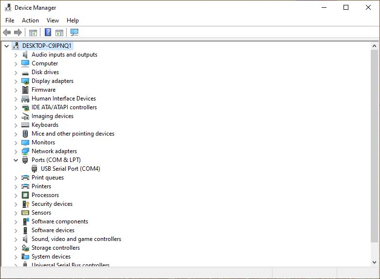
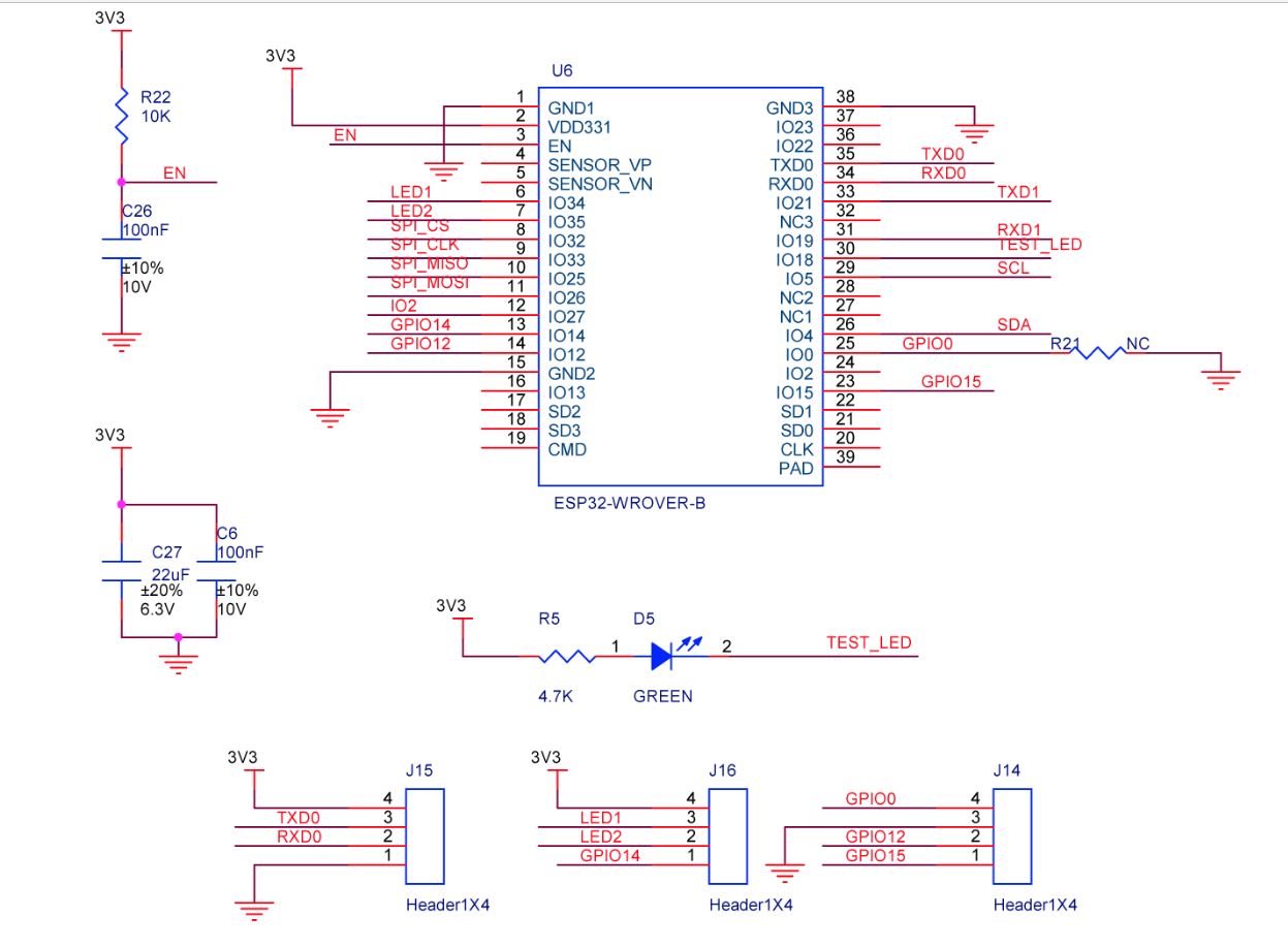
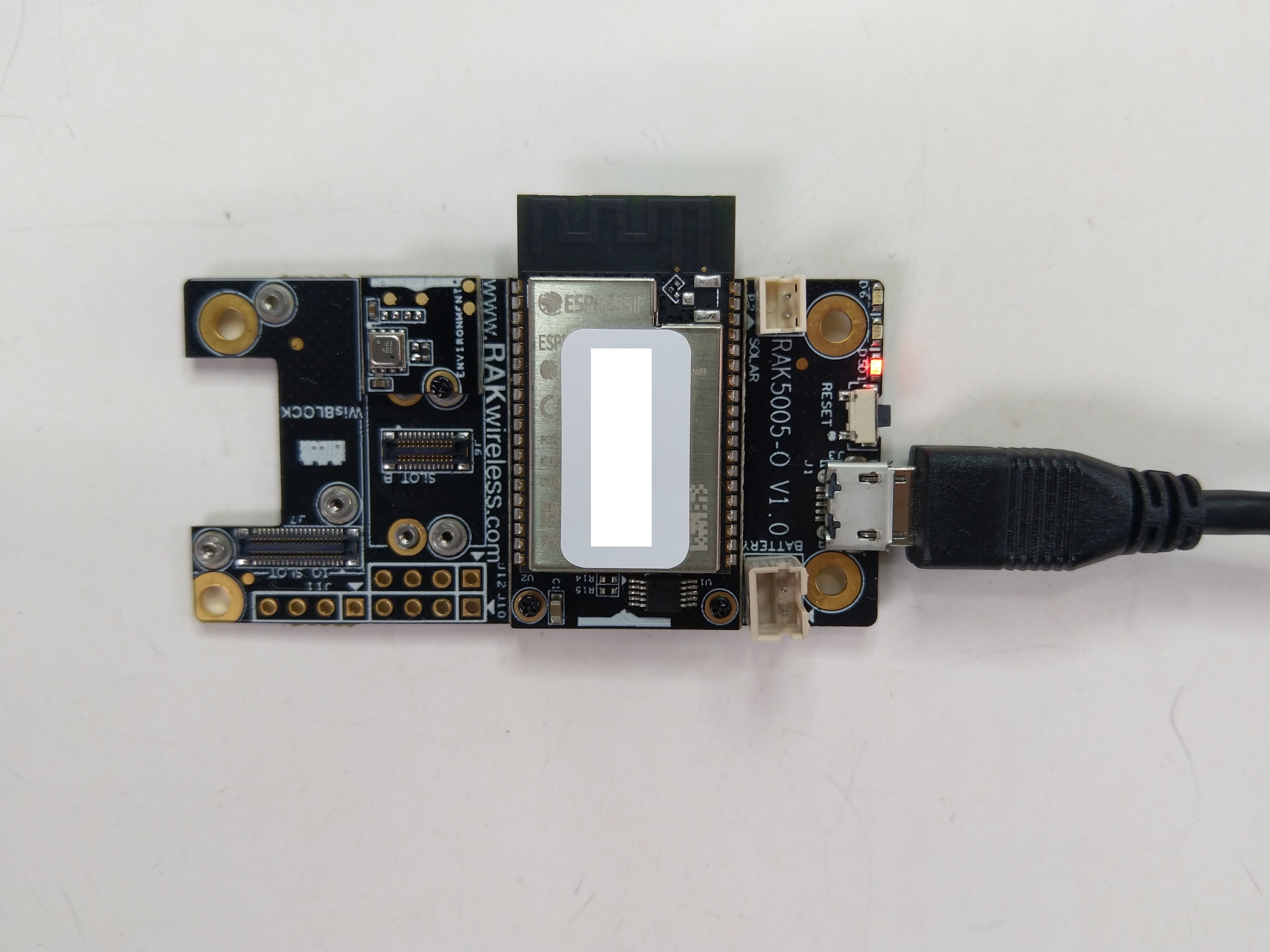
The RAK2305 Low Level Developer documentation described how to upload software developed with the Arduino tools by putting the ESP32 into “bootloader mode”. This is done by connecting (with the white jumper) the GPIO0 and GND pins on J14, and pressing the reset button.
The RAK2305 has has one onboard LED(TEST_LED) attached to IO18 which I added to the .NET nanoFrameworkBlinky sample.
//
// Copyright (c) .NET Foundation and Contributors
// See LICENSE file in the project root for full license information.
//
//
using System;
using System.Device.Gpio;
using System.Threading;
using nanoFramework.Hardware.Esp32;

namespace Blinky
{
   public class Program
   {
      private static GpioController s_GpioController;

      public static void Main()
      {
         s_GpioController = new GpioController();

         // pick a board, uncomment one line for GpioPin; default is STM32F769I_DISCO

         // DISCOVERY4: PD15 is LED6
         //GpioPin led = s_GpioController.OpenPin(PinNumber('D', 15), PinMode.Output);

         // ESP32 DevKit: 4 is a valid GPIO pin in, some boards like Xiuxin ESP32 may require GPIO Pin 2 instead.
         //GpioPin led = s_GpioController.OpenPin(4, PinMode.Output);

         // FEATHER S2:
         //GpioPin led = s_GpioController.OpenPin(13, PinMode.Output);

         // F429I_DISCO: PG14 is LEDLD4
         //GpioPin led = s_GpioController.OpenPin(PinNumber('G', 14), PinMode.Output);

         // NETDUINO 3 Wifi: A10 is LED onboard blue
         //GpioPin led = s_GpioController.OpenPin(PinNumber('A', 10), PinMode.Output);

         // QUAIL: PE15 is LED1
         //GpioPin led = s_GpioController.OpenPin(PinNumber('E', 15), PinMode.Output);

         // STM32F091RC: PA5 is LED_GREEN
         //GpioPin led = s_GpioController.OpenPin(PinNumber('A', 5), PinMode.Output);

         // STM32F746_NUCLEO: PB75 is LED2
         //GpioPin led = s_GpioController.OpenPin(PinNumber('B', 7), PinMode.Output);

         //STM32F769I_DISCO: PJ5 is LD2
         //GpioPin led = s_GpioController.OpenPin(PinNumber('J', 5), PinMode.Output);

         // ST_B_L475E_IOT01A: PB14 is LD2
         //GpioPin led = s_GpioController.OpenPin(PinNumber('B', 14), PinMode.Output);

         // STM32L072Z_LRWAN1: PA5 is LD2
         //GpioPin led = s_GpioController.OpenPin(PinNumber('A', 5), PinMode.Output);

         // TI CC13x2 Launchpad: DIO_07 it's the green LED
         //GpioPin led = s_GpioController.OpenPin(7, PinMode.Output);

         // TI CC13x2 Launchpad: DIO_06 it's the red LED
         //GpioPin led = s_GpioController.OpenPin(6, PinMode.Output);

         // ULX3S FPGA board: for the red D22 LED from the ESP32-WROOM32, GPIO5
         //GpioPin led = s_GpioController.OpenPin(5, PinMode.Output);

         // Silabs SLSTK3701A: LED1 PH14 is LLED1
         //GpioPin led = s_GpioController.OpenPin(PinNumber('H', 14), PinMode.Output);

         // RAK11200 on RAK5005
         //GpioPin led = s_GpioController.OpenPin(Gpio.IO12, PinMode.Output); // LED1 Green
         //GpioPin led = s_GpioController.OpenPin(Gpio.IO02, PinMode.Output); // LED2 Blue

         // RAK11200 on RAK19001 needs battery connected or power switch in rechargeable position.
         //GpioPin led = s_GpioController.OpenPin(Gpio.IO12, PinMode.Output); // LED1 Green
         //GpioPin led = s_GpioController.OpenPin(Gpio.IO02, PinMode.Output); // LED2 Blue

         // RAK2305
         //GpioPin led = s_GpioController.OpenPin(Gpio.IO18, PinMode.Output); // LED Green (Test LED) on device

         // RAK2305 On 5005 throws exceptions
         //GpioPin led = s_GpioController.OpenPin(Gpio.IO34, PinMode.Output); // LED1 Green
         //GpioPin led = s_GpioController.OpenPin(Gpio.IO35, PinMode.Output); // LED2 Blue

         // RAK2305 On 17001 throws exceptions
         //GpioPin led = s_GpioController.OpenPin(Gpio.IO34, PinMode.Output); // LED1 Green
         //GpioPin led = s_GpioController.OpenPin(Gpio.IO35, PinMode.Output); // LED2 Blue

         led.Write(PinValue.Low);

         while (true)
         {
            led.Toggle();
            Thread.Sleep(125);
            led.Toggle();
            Thread.Sleep(125);
            led.Toggle();
            Thread.Sleep(125);
            led.Toggle();
            Thread.Sleep(525);
         }
      }

      static int PinNumber(char port, byte pin)
      {
         if (port < 'A' || port > 'J')
            throw new ArgumentException();

         return ((port - 'A') * 16) + pin;
      }
   }
}
I added the RAK2305 configuration to my version of the nanoFramework Blinky sample and could reliably flash the onboard LED.
The RAK11200 documentation described how to upload software developed with the Arduino tools by putting the ESP32 into “bootloader mode” by connecting the BOOT0 and GND pins, then pressing the reset button.
RAK11200 BOOT0 & GND pins connected to
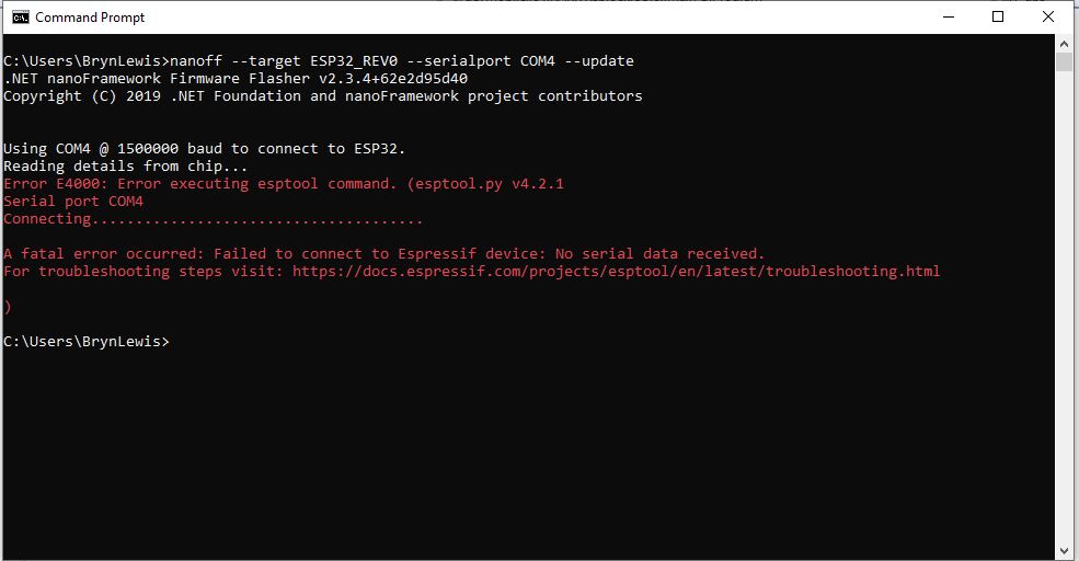
After some “trial and error” the download process worked pretty reliably…
The RAK11200 has two LEDs, a blue attached to IO02 and a green one attached to IO12.
//
// Copyright (c) .NET Foundation and Contributors
// See LICENSE file in the project root for full license information.
//
//
using System;
using System.Device.Gpio;
using System.Threading;
using nanoFramework.Hardware.Esp32;

namespace Blinky
{
   public class Program
   {
      private static GpioController s_GpioController;
      public static void Main()
      {
         s_GpioController = new GpioController();

         // pick a board, uncomment one line for GpioPin; default is STM32F769I_DISCO

         // DISCOVERY4: PD15 is LED6
         //GpioPin led = s_GpioController.OpenPin(PinNumber('D', 15), PinMode.Output);

         // ESP32 DevKit: 4 is a valid GPIO pin in, some boards like Xiuxin ESP32 may require GPIO Pin 2 instead.
         //GpioPin led = s_GpioController.OpenPin(4, PinMode.Output);

         // FEATHER S2:
         //GpioPin led = s_GpioController.OpenPin(13, PinMode.Output);

         // F429I_DISCO: PG14 is LEDLD4
         //GpioPin led = s_GpioController.OpenPin(PinNumber('G', 14), PinMode.Output);

         // NETDUINO 3 Wifi: A10 is LED onboard blue
         //GpioPin led = s_GpioController.OpenPin(PinNumber('A', 10), PinMode.Output);

         // QUAIL: PE15 is LED1
         //GpioPin led = s_GpioController.OpenPin(PinNumber('E', 15), PinMode.Output);

         // STM32F091RC: PA5 is LED_GREEN
         //GpioPin led = s_GpioController.OpenPin(PinNumber('A', 5), PinMode.Output);

         // STM32F746_NUCLEO: PB75 is LED2
         //GpioPin led = s_GpioController.OpenPin(PinNumber('B', 7), PinMode.Output);

         //STM32F769I_DISCO: PJ5 is LD2
         //GpioPin led = s_GpioController.OpenPin(PinNumber('J', 5), PinMode.Output);

         // ST_B_L475E_IOT01A: PB14 is LD2
         //GpioPin led = s_GpioController.OpenPin(PinNumber('B', 14), PinMode.Output);

         // STM32L072Z_LRWAN1: PA5 is LD2
         //GpioPin led = s_GpioController.OpenPin(PinNumber('A', 5), PinMode.Output);

         // TI CC13x2 Launchpad: DIO_07 it's the green LED
         //GpioPin led = s_GpioController.OpenPin(7, PinMode.Output);

         // TI CC13x2 Launchpad: DIO_06 it's the red LED
         //GpioPin led = s_GpioController.OpenPin(6, PinMode.Output);

         // ULX3S FPGA board: for the red D22 LED from the ESP32-WROOM32, GPIO5
         //GpioPin led = s_GpioController.OpenPin(5, PinMode.Output);

         // Silabs SLSTK3701A: LED1 PH14 is LLED1
         //GpioPin led = s_GpioController.OpenPin(PinNumber('H', 14), PinMode.Output);

         // RAK11200 on RAK5005
         //GpioPin led = s_GpioController.OpenPin(Gpio.IO12, PinMode.Output); // LED1 Green
         //GpioPin led = s_GpioController.OpenPin(Gpio.IO02, PinMode.Output); // LED2 Blue

         // RAK11200 on RAK19001 needs battery connected or power switch in rechargeable position.
         //GpioPin led = s_GpioController.OpenPin(Gpio.IO12, PinMode.Output); // LED1 Green
         //GpioPin led = s_GpioController.OpenPin(Gpio.IO02, PinMode.Output); // LED2 Blue

         // RAK2305
         //GpioPin led = s_GpioController.OpenPin(Gpio.IO18, PinMode.Output); // LED Green (Test LED) on device

         // RAK2305 On 5005 throws exceptions
         //GpioPin led = s_GpioController.OpenPin(Gpio.IO34, PinMode.Output); // LED1 Green
         //GpioPin led = s_GpioController.OpenPin(Gpio.IO35, PinMode.Output); // LED2 Blue

         // RAK2305 On 17001 throws exceptions
         //GpioPin led = s_GpioController.OpenPin(Gpio.IO34, PinMode.Output); // LED1 Green
         //GpioPin led = s_GpioController.OpenPin(Gpio.IO35, PinMode.Output); // LED2 Blue

         led.Write(PinValue.Low);

         while (true)
         {
            led.Toggle();
            Thread.Sleep(125);
            led.Toggle();
            Thread.Sleep(125);
            led.Toggle();
            Thread.Sleep(125);
            led.Toggle();
            Thread.Sleep(525);
         }
      }

      static int PinNumber(char port, byte pin)
      {
         if (port < 'A' || port > 'J')
            throw new ArgumentException();

         return ((port - 'A') * 16) + pin;
      }
   }
}
I added the RAK11200 configuration to my version of the nanoFramework Blinky sample and could reliably flash either of the LEDs.
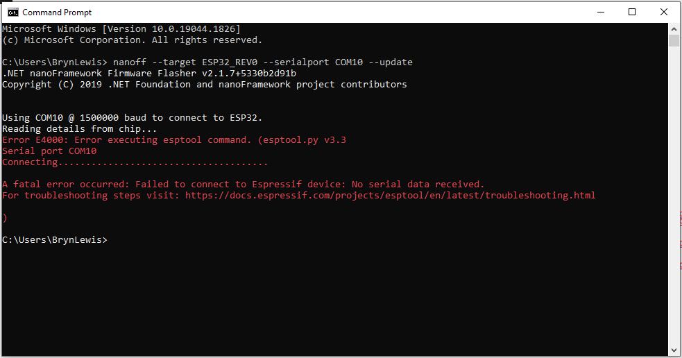
While “smoke testing” the application I noticed that if I erased the flash, power cycled the device, then ran the application the first execution would fail because the SemtechSX127X could not be detected.
SX127XLoRaDeviceClient first execution startup failure
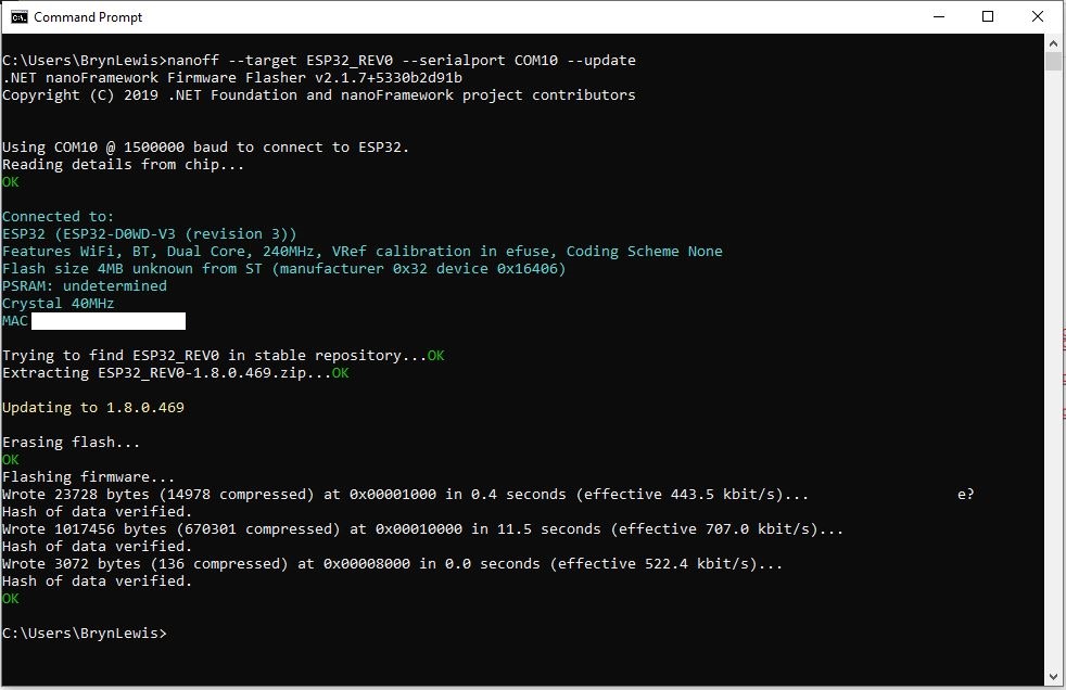
SX127XLoRaDeviceClient second execution startup success
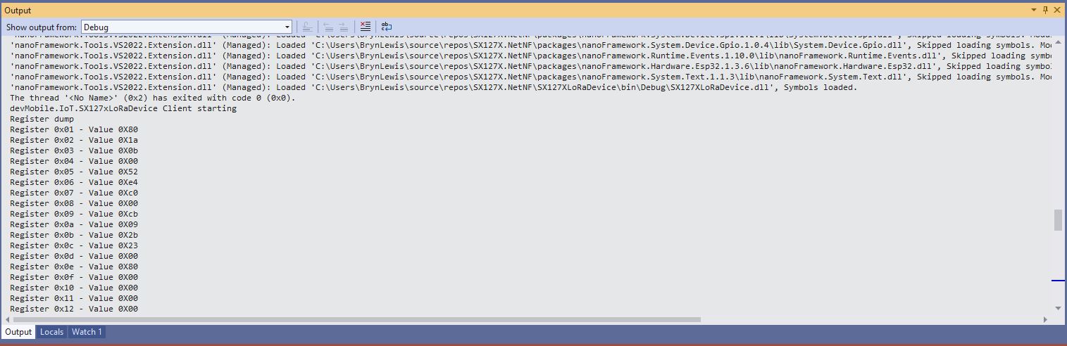
After printing the code out and reviewing it I noticed that the Configuration.SetPinFunction for the Serial Peripheral Interface(SPI) Master Out Slave In(MOSI), MOSI(Master In Slave Out) and Clock pins was after the opening of the SPI port.
static void Main(string[] args)
{
	byte SendCount = 0;
#if ESP32_WROOM_32_LORA_1_CHANNEL // No reset line for this device as it isn't connected on SX127X
	int chipSelectLine = Gpio.IO16;
	int dio0PinNumber = Gpio.IO26;
#endif
#if NETDUINO3_WIFI
	// Arduino D10->PB10
	int chipSelectLine = PinNumber('B', 10);
	// Arduino D9->PE5
	int resetPinNumber = PinNumber('E', 5);
	// Arduino D2 -PA3
	int dio0PinNumber = PinNumber('A', 3);
#endif
#if ST_STM32F769I_DISCOVERY
	// Arduino D10->PA11
	int chipSelectLine = PinNumber('A', 11);
	// Arduino D9->PH6
	int resetPinNumber = PinNumber('H', 6);
	// Arduino D2->PA4
	int dio0PinNumber = PinNumber('J', 1);
#endif
	Console.WriteLine("devMobile.IoT.SX127xLoRaDevice Range Tester starting");

	try
	{
#f ESP32_WROOM_32_LORA_1_CHANNEL
		Configuration.SetPinFunction(Gpio.IO12, DeviceFunction.SPI1_MISO);
		Configuration.SetPinFunction(Gpio.IO13, DeviceFunction.SPI1_MOSI);
		Configuration.SetPinFunction(Gpio.IO14, DeviceFunction.SPI1_CLOCK);
#endif

		var settings = new SpiConnectionSettings(SpiBusId, chipSelectLine)
		{
			ClockFrequency = 1000000,
			Mode = SpiMode.Mode0,// From SemTech docs pg 80 CPOL=0, CPHA=0
			SharingMode = SpiSharingMode.Shared
		};

		using (_gpioController = new GpioController())
		using (SpiDevice spiDevice = new SpiDevice(settings))
		{

#if ESP32_WROOM_32_LORA_1_CHANNEL
			_sx127XDevice = new SX127XDevice(spiDevice, _gpioController, dio0Pin: dio0PinNumber);
#endif

#if NETDUINO3_WIFI || ST_STM32F769I_DISCOVERY
			_sx127XDevice = new SX127XDevice(spiDevice, _gpioController, dio0Pin: dio0PinNumber, resetPin:resetPinNumber);
#endif
...

		}
		catch (Exception ex)
		{
				Console.WriteLine(ex.Message);
		}
	}
I assume that the first execution after erasing the flash and power cycling the device, the SPI port pin assignments were not configured when the port was opened, then on the next execution the port was pre-configured.
The RangeTester application flashes on onboard Light Emitting Diode(LED) every time a valid message is received. But, on the ESP32 it turned on when the first message arrived and didn’t turn off. After discussion on the nanoFramework Discord this has been identified as an issue(May 2022).
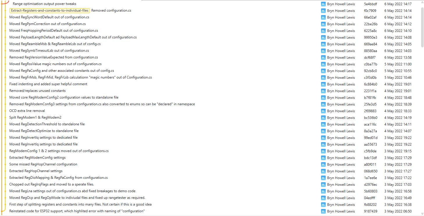
I had been planning this for a while, then the code broke when I tried to build a version for my SparkFun LoRa Gateway-1-Channel (ESP32). There was a namespace (static configuration class in configuration.cs) collision and the length of SX127XDevice.cs file was getting silly.
This refactor took a couple of days and really changed the structure of the library.
VS2022 Solution structure after refactoring
I went through the SX127XDevice.cs extracting the enumerations, masks and defaults associated with the registers the library supports.
The library is designed to be a approximate .NET nanoFramework equivalent of Arduino-LoRa so it doesn’t support/implement all of the functionality of the SemtechSX127X. Still got a bit of refactoring to go but the structure is slowly improving.
I use Fork to manage my Github repositories, it’s an excellent product especially as it does a pretty good job of keeping me from screwing up.
While trying different myNET nanoFrameworkSemtech SX127X library configurations so I could explore the interactions of RegOcp(Over current protection) + RegOcpTrim I noticed something odd about the power consumption so I revisited how the output power is calculated.
Netduino3 Wifi with USB power consumption measurement
The RegPaConfig register has three settings PaSelect(RFO & PA_BOOST), MaxPower(0..7), and OutputPower(0..15). When in RFO mode the pOut has a range of -4 to 15 and PA_BOOST mode has a range of 2 to 20.
RegPaConfig register configuration options
RegPaDac register configuration options
The SX127X also has a power amplifier attached to the PA_BOOST pin and a higher power amplifier which is controlled by the RegPaDac register.
// Set RegPAConfig & RegPaDac if powerAmplifier/OutputPower settings not defaults
if ((powerAmplifier != Configuration.RegPAConfigPASelect.Default) || (outputPower != Configuration.OutputPowerDefault))
{
	if (powerAmplifier == Configuration.RegPAConfigPASelect.PABoost)
	{
		byte regPAConfigValue = (byte)Configuration.RegPAConfigPASelect.PABoost;

		// Validate the minimum and maximum PABoost outputpower
		if ((outputPower < Configuration.OutputPowerPABoostMin) || (outputPower > Configuration.OutputPowerPABoostMax))
		{
			throw new ApplicationException($"PABoost {outputPower}dBm Min power {Configuration.OutputPowerPABoostMin} to Max power {Configuration.OutputPowerPABoostMax}");
		}

		if (outputPower <= Configuration.OutputPowerPABoostPaDacThreshhold)
		{
			// outputPower 0..15 so pOut is 2=17-(15-0)...17=17-(15-15)
			regPAConfigValue |= (byte)Configuration.RegPAConfigMaxPower.Default;
			regPAConfigValue |= (byte)(outputPower - 2);

			_registerManager.WriteByte((byte)Configuration.Registers.RegPAConfig, regPAConfigValue);
			_registerManager.WriteByte((byte)Configuration.Registers.RegPaDac, (byte)Configuration.RegPaDac.Normal);
		}
		else
		{
			// outputPower 0..15 so pOut is 5=20-(15-0)...20=20-(15-15) // See https://github.com/adafruit/RadioHead/blob/master/RH_RF95.cpp around line 411 could be 23dBm
			regPAConfigValue |= (byte)Configuration.RegPAConfigMaxPower.Default;
			regPAConfigValue |= (byte)(outputPower - 5);

			_registerManager.WriteByte((byte)Configuration.Registers.RegPAConfig, regPAConfigValue);
			_registerManager.WriteByte((byte)Configuration.Registers.RegPaDac, (byte)Configuration.RegPaDac.Boost);
		}
	}
	else
	{
		byte regPAConfigValue = (byte)Configuration.RegPAConfigPASelect.Rfo;

		// Validate the minimum and maximum RFO outputPower
		if ((outputPower < Configuration.OutputPowerRfoMin) || (outputPower > Configuration.OutputPowerRfoMax))
		{
			throw new ApplicationException($"RFO {outputPower}dBm Min power {Configuration.OutputPowerRfoMin} to Max power {Configuration.OutputPowerRfoMax}");
		}

		// Set MaxPower and Power calculate pOut = PMax-(15-outputPower), pMax=10.8 + 0.6*MaxPower
		if (outputPower > Configuration.OutputPowerRfoThreshhold)
		{
			// pMax 15=10.8+0.6*7 with outputPower 0...15 so pOut is 15=pMax-(15-0)...0=pMax-(15-15)
			regPAConfigValue |= (byte)Configuration.RegPAConfigMaxPower.Max;
			regPAConfigValue |= (byte)(outputPower + 0);
		}
		else
		{
			// pMax 10.8=10.8+0.6*0 with output power 0..15 so pOut is -4=10-(15-0)...10.8=10.8-(15-15)
			regPAConfigValue |= (byte)Configuration.RegPAConfigMaxPower.Min;
			regPAConfigValue |= (byte)(outputPower + 4);
		}

		_registerManager.WriteByte((byte)Configuration.Registers.RegPAConfig, regPAConfigValue);
		_registerManager.WriteByte((byte)Configuration.Registers.RegPaDac, (byte)Configuration.RegPaDac.Normal);
	}
}

// Set RegOcp if any of the settings not defaults
if ((ocpOn != Configuration.RegOcp.Default) || (ocpTrim != Configuration.RegOcpTrim.Default))
{
	byte regOcpValue = (byte)ocpTrim;

	regOcpValue |= (byte)ocpOn;

	_registerManager.WriteByte((byte)Configuration.Registers.RegOcp, regOcpValue);
}
After reviewing the code I realised that the the RegPaDac test around line 14 should <= rather than <
All the previous versions of my.NET nanoFrameworkSemtech SX127X (LoRa® Mode) library only supported a Dio0 (RegDioMapping1 bits 6&7) EventHandler. This version supports mapping Dio0, Dio1, Dio2, Dio3, Dio4 and Dio5.
The SX127XLoRaDeviceClient main now has OnRxTimeout, OnReceive, OnPayloadCrcError, OnValidHeader, OnTransmit, OnChannelActivityDetectionDone, OnFhssChangeChannel, and OnChannelActivityDetected event handlers (Based on RegIrqFlags bit ordering)
The Dio0 pin number is the only required pin number parameter, the resetPin, and Dio1 thru Dio5 pin numbers are optional. All the RegDioMapping1 and RegDioMapping2 mappings are disabled on intialisation so there should be no events while the SX127X is being configured.
public SX127XDevice(SpiDevice spiDevice, GpioController gpioController,
int dio0Pin,
int resetPin = 0, // Odd order so as not to break exisiting code
int dio1Pin = 0,
int dio2Pin = 0,
int dio3Pin = 0,
int dio4Pin = 0,
int dio5Pin = 0
)
{
_gpioController = gpioController;
// Factory reset pin configuration
if (resetPin != 0)
{
_resetPin = resetPin;
_gpioController.OpenPin(resetPin, PinMode.Output);
_gpioController.Write(resetPin, PinValue.Low);
Thread.Sleep(20);
_gpioController.Write(resetPin, PinValue.High);
Thread.Sleep(50);
}
_registerManager = new RegisterManager(spiDevice, RegisterAddressReadMask, RegisterAddressWriteMask);
// Once the pins setup check that SX127X chip is present
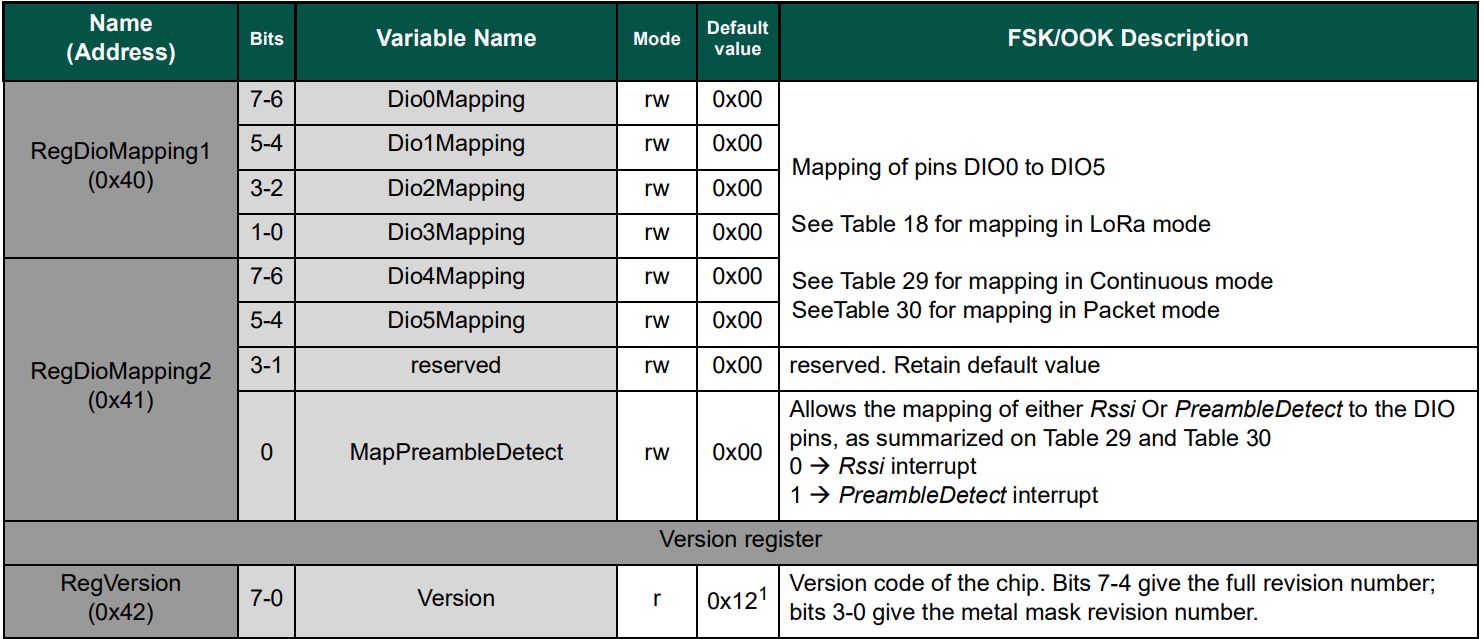
Byte regVersionValue = _registerManager.ReadByte((byte)Configuration.Registers.RegVersion);
if (regVersionValue != Configuration.RegVersionValueExpected)
{
throw new ApplicationException("Semtech SX127X not found");
}
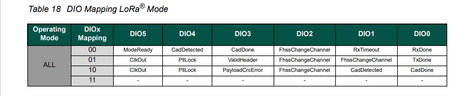
// See Table 18 DIO Mapping LoRa® Mode
Configuration.RegDioMapping1 regDioMapping1Value = Configuration.RegDioMapping1.Dio0None;
regDioMapping1Value |= Configuration.RegDioMapping1.Dio1None;
regDioMapping1Value |= Configuration.RegDioMapping1.Dio2None;
regDioMapping1Value |= Configuration.RegDioMapping1.Dio3None;
_registerManager.WriteByte((byte)Configuration.Registers.RegDioMapping1, (byte)regDioMapping1Value);
// Currently no easy way to test this with available hardware
//Configuration.RegDioMapping2 regDioMapping2Value = Configuration.RegDioMapping2.Dio4None;
//regDioMapping2Value = Configuration.RegDioMapping2.Dio5None;
//_registerManager.WriteByte((byte)Configuration.Registers.RegDioMapping2, (byte)regDioMapping2Value);
// Interrupt pin for RXDone, TXDone, and CadDone notification
_gpioController.OpenPin(dio0Pin, PinMode.InputPullDown);
_gpioController.RegisterCallbackForPinValueChangedEvent(dio0Pin, PinEventTypes.Rising, InterruptGpioPin_ValueChanged);
// RxTimeout, FhssChangeChannel, and CadDetected
if (dio1Pin != 0)
{
_gpioController.OpenPin(dio1Pin, PinMode.InputPullDown);
_gpioController.RegisterCallbackForPinValueChangedEvent(dio1Pin, PinEventTypes.Rising, InterruptGpioPin_ValueChanged);
}
// FhssChangeChannel, FhssChangeChannel, and FhssChangeChannel
if (dio2Pin != 0)
{
_gpioController.OpenPin(dio2Pin, PinMode.InputPullDown);
_gpioController.RegisterCallbackForPinValueChangedEvent(dio2Pin, PinEventTypes.Rising, InterruptGpioPin_ValueChanged);
}
// CadDone, ValidHeader, and PayloadCrcError
if (dio3Pin != 0)
{
_gpioController.OpenPin(dio3Pin, PinMode.InputPullDown);
_gpioController.RegisterCallbackForPinValueChangedEvent(dio3Pin, PinEventTypes.Rising, InterruptGpioPin_ValueChanged);
}
// CadDetected, PllLock and PllLock
if (dio4Pin != 0)
{
_gpioController.OpenPin(dio4Pin, PinMode.InputPullDown);
_gpioController.RegisterCallbackForPinValueChangedEvent(dio4Pin, PinEventTypes.Rising, InterruptGpioPin_ValueChanged);
}
// ModeReady, ClkOut and ClkOut
if (dio5Pin != 0)
{
_gpioController.OpenPin(dio5Pin, PinMode.InputPullDown);
_gpioController.RegisterCallbackForPinValueChangedEvent(dio5Pin, PinEventTypes.Rising, InterruptGpioPin_ValueChanged);
}
}
The same event handler (InterruptGpioPin_ValueChanged) is used for Dio0 thru Dio5. Each event has a “process” method and the RegIrqFlags register controls which one(s) are called.
The RegIrqFlags bits are cleared individually (with regIrqFlagsToClear) at the end of the event handler. Initially I cleared all the flags by writing 0xFF to RegIrqFlags but this caused issues when there were multiple bits set e.g. CadDone along with CadDetected.
It took some experimentation with the SX127xLoRaDeviceClient application to “reliably” trigger events for testing. To generate CAD Detected event, I had to modify one of the Arduino-LoRa sample applications to send messages without a delay, then have it running as the SX127xLoRaDeviceClient application was starting.
While updating my.NET nanoFrameworkSemtech SX127X library I revisited (because I thought it might still be wrong) how the output power is calculated. I started with the overview of the transmitter architecture in in the datasheet…
SX127X Overview of transmission pipeline
The RegPaConfig register has three settings PaSelect(RFO & PA_BOOST), MaxPower(0..7), and OutputPower(0..15). When in RFO mode the pOut has a range of -4 to 15 and PA_BOOST mode has a range of 2 to 20. (The AdaFruitversion of the RadioHead library has differences to the Semtech Lora-net/LoRaMac-Node libraries)
The SX127X also has a power amplifier attached to the PA_BOOST pin and a higher power amplifier which is controlled by the RegPaDac register.
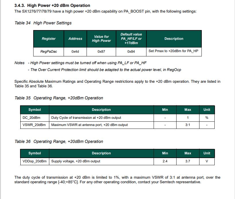
High power mode overview
RegPaDac register configuration options
The RegOcp (over current protection) has to be relaxed for the higher power modes
RegPaConfig register configuration options
I started with the Semtech Lora-net/LoRaMac-Node library which reads the RegPaConfig, RegPaSelect and RegPaDac registers then does any updates required.
I also reviewed the Arduino-LoRaSemtech library which only writes to the RegPaConfig, RegPaSelect and RegPaDac registers.
void LoRaClass::setTxPower(int level, int outputPin)
{
  if (PA_OUTPUT_RFO_PIN == outputPin) {
    // RFO
    if (level < 0) {
      level = 0;
    } else if (level > 14) {
      level = 14;
    }

    writeRegister(REG_PA_CONFIG, 0x70 | level);
  } else {
    // PA BOOST
    if (level > 17) {
      if (level > 20) {
        level = 20;
      }

      // subtract 3 from level, so 18 - 20 maps to 15 - 17
      level -= 3;

      // High Power +20 dBm Operation (Semtech SX1276/77/78/79 5.4.3.)
      writeRegister(REG_PA_DAC, 0x87);
      setOCP(140);
    } else {
      if (level < 2) {
        level = 2;
      }
      //Default value PA_HF/LF or +17dBm
      writeRegister(REG_PA_DAC, 0x84);
      setOCP(100);
    }

    writeRegister(REG_PA_CONFIG, PA_BOOST | (level - 2));
  }
}
I updated the output power configuration code in the Initialise method of the SX127X library. After reviewing the SX127X datasheet I extended the way the pOut is calculated in RFO mode. The code uses two values for MaxPower(RegPAConfigMaxPower.Min & RegPAConfigMaxPower.Max) so that the full RTO output power range was available.
// Set RegPAConfig & RegPaDac if powerAmplifier/OutputPower settings not defaults
if ((powerAmplifier != Configuration.RegPAConfigPASelect.Default) || (outputPower != Configuration.OutputPowerDefault))
{
	if (powerAmplifier == Configuration.RegPAConfigPASelect.PABoost)
	{
		byte regPAConfigValue = (byte)Configuration.RegPAConfigPASelect.PABoost;

		// Validate the minimum and maximum PABoost outputpower
		if ((outputPower < Configuration.OutputPowerPABoostMin) || (outputPower > Configuration.OutputPowerPABoostMax))
		{
			throw new ApplicationException($"PABoost {outputPower}dBm Min power {Configuration.OutputPowerPABoostMin} to Max power {Configuration.OutputPowerPABoostMax}");
		}

		if (outputPower < Configuration.OutputPowerPABoostPaDacThreshhold)
		{
			// outputPower 0..15 so pOut is 2=17-(15-0)...17=17-(15-15)
			regPAConfigValue |= (byte)Configuration.RegPAConfigMaxPower.Default;
			regPAConfigValue |= (byte)(outputPower - 2);

			_registerManager.WriteByte((byte)Configuration.Registers.RegPAConfig, regPAConfigValue);
			_registerManager.WriteByte((byte)Configuration.Registers.RegPaDac, (byte)Configuration.RegPaDac.Normal);
		}
		else
		{
			// outputPower 0..15 so pOut is 5=20-(15-0)...20=20-(15-15) // See https://github.com/adafruit/RadioHead/blob/master/RH_RF95.cpp around line 411 could be 23dBm
			regPAConfigValue |= (byte)Configuration.RegPAConfigMaxPower.Default;
			regPAConfigValue |= (byte)(outputPower - 5);

			_registerManager.WriteByte((byte)Configuration.Registers.RegPAConfig, regPAConfigValue);
			_registerManager.WriteByte((byte)Configuration.Registers.RegPaDac, (byte)Configuration.RegPaDac.Boost);
		}
	}
	else
	{
		byte regPAConfigValue = (byte)Configuration.RegPAConfigPASelect.Rfo;

		// Validate the minimum and maximum RFO outputPower
		if ((outputPower < Configuration.OutputPowerRfoMin) || (outputPower > Configuration.OutputPowerRfoMax))
		{
			throw new ApplicationException($"RFO {outputPower}dBm Min power {Configuration.OutputPowerRfoMin} to Max power {Configuration.OutputPowerRfoMax}");
		}

		// Set MaxPower and Power calculate pOut = PMax-(15-outputPower), pMax=10.8 + 0.6*MaxPower
		if (outputPower > Configuration.OutputPowerRfoThreshhold)
		{
			// pMax 15=10.8+0.6*7 with outputPower 0...15 so pOut is 15=pMax-(15-0)...0=pMax-(15-15)
			regPAConfigValue |= (byte)Configuration.RegPAConfigMaxPower.Max;
			regPAConfigValue |= (byte)(outputPower + 0);
		}
		else
		{
			// pMax 10.8=10.8+0.6*0 with output power 0..15 so pOut is -4=10-(15-0)...10.8=10.8-(15-15)
			 regPAConfigValue |= (byte)Configuration.RegPAConfigMaxPower.Min;
			regPAConfigValue |= (byte)(outputPower + 4);
		}

		_registerManager.WriteByte((byte)Configuration.Registers.RegPAConfig, regPAConfigValue);
		_registerManager.WriteByte((byte)Configuration.Registers.RegPaDac, (byte)Configuration.RegPaDac.Normal);
	}
}
The formula for pOut and pMax in RegPaConfig documentation is included in the source code so I could manually calculate (including edge cases) the values as part of my testing. I ran the SX127XLoRaDeviceClient and inspected the PaConfig & RegPaDac in the Visual Studio 2022 debugger.
PABoost
Output power = 1
Output power = 21
Exception

Output power = 2
PaConfig = 192
RegPaDac = normal
	1100 0000

Output power = 16
PaConfig = 206
RegPaDac = normal
	1100 1110

Output power = 17
PaConfig = 204
RegPacDac = Normal
	1100 1100

Output power = 18
PaConfig = 205
RegPacDac = Boost
	1100 1101

Output power = 19
PaConfig = 206
RegPacDac = Boost
	1100 1110

Output power = 20
PaConfig = 207
RegPacDac = Boost
	1100 1111

RFO
Output power = -5
Output power = 16
Exception

Output power = -4
PAConfig = 0
	0000 0000

Output power = -1
PAConfig = 3
	0000 0011

Output power = 0
PAConfig = 4
	0000 0100

Output power = 1
PAConfig = 113
	0111 0001

OutputPower = 14
PAConfig = 126
	0111 1110

OutputPower = 15
PAConfig = 127
	0111 1111
I need to borrow some test gear to check my implementation
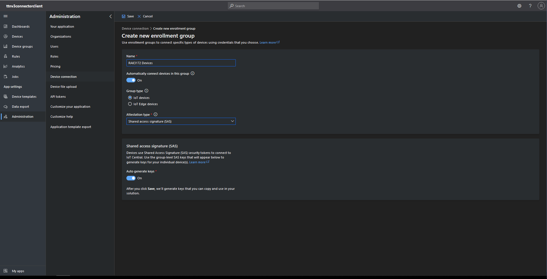
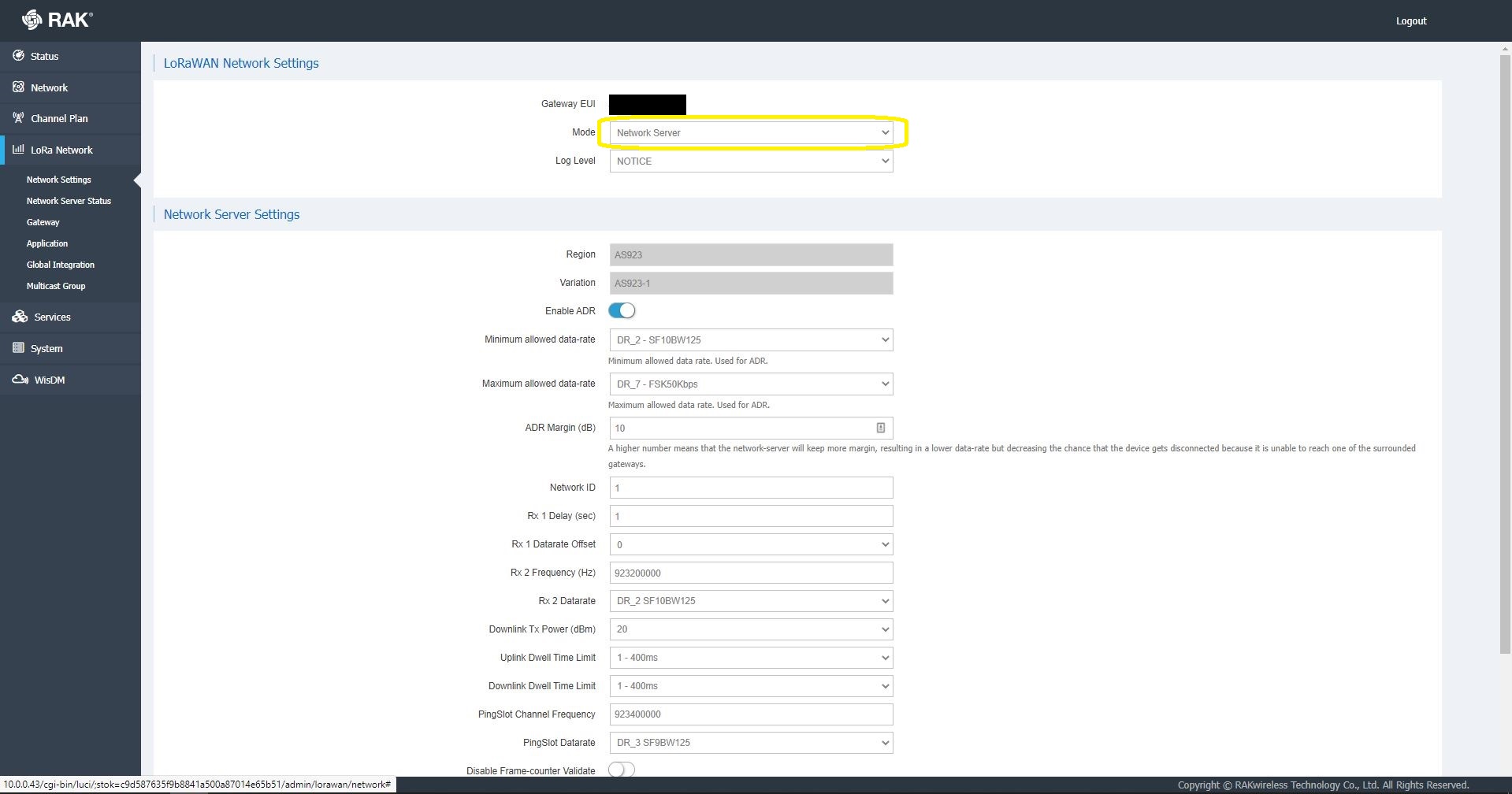
I then started exploring how applications and devices are provisioned in the RAK Network Server.
RAK 7258 Network Server applications list
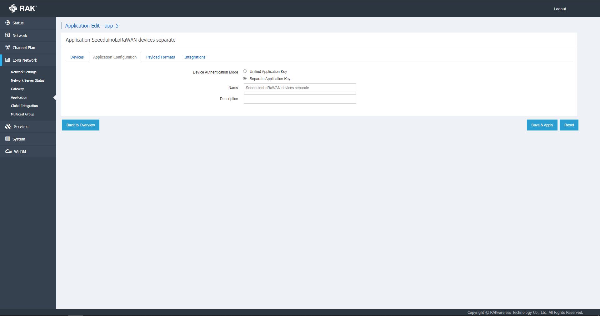
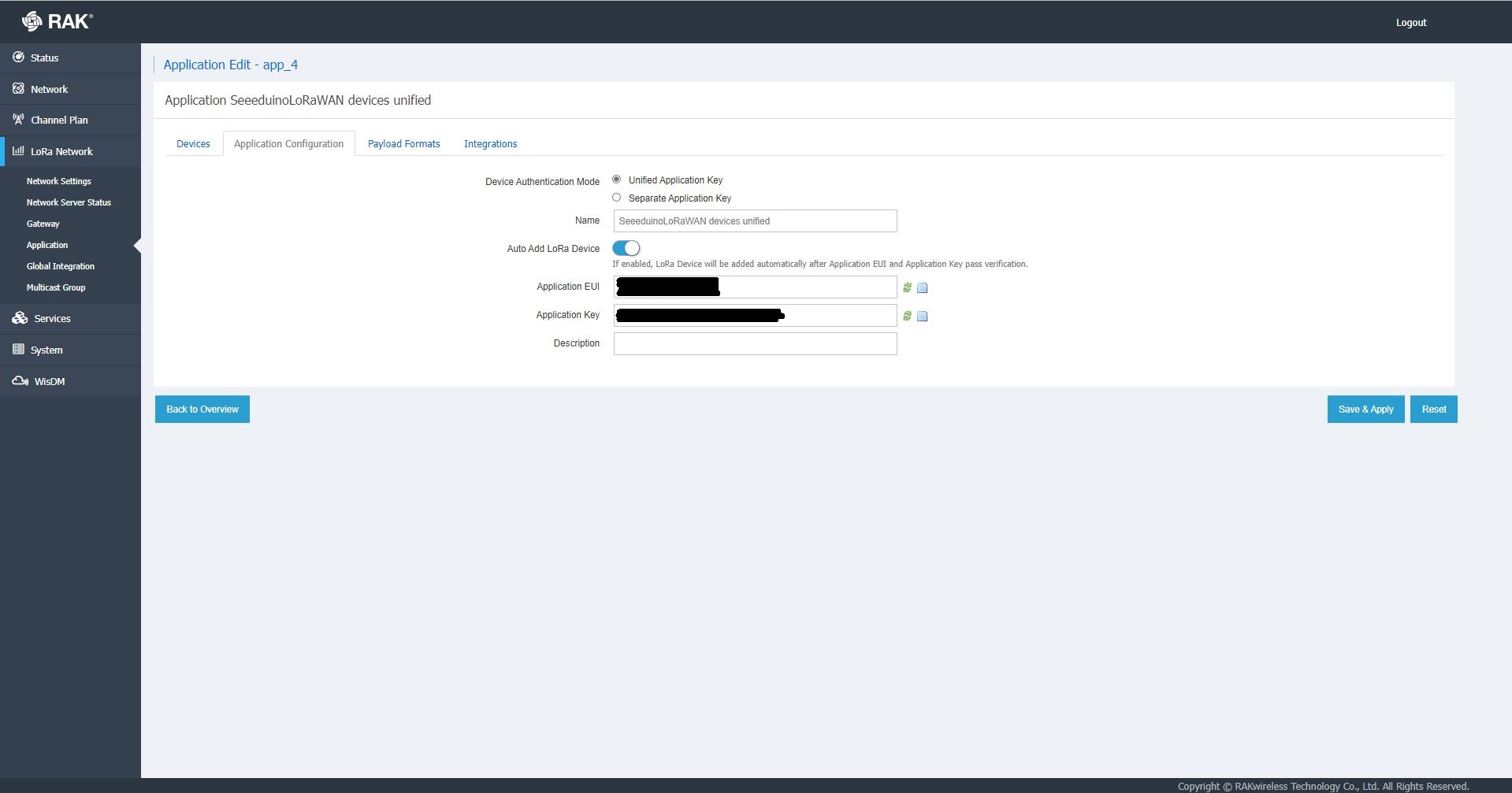
The network server software has “unified” and “separate” “Device authentication mode”s and will “auto Add LoRa Device”s if enabled.
RAK 7258 Network Server Separate Application basic setup
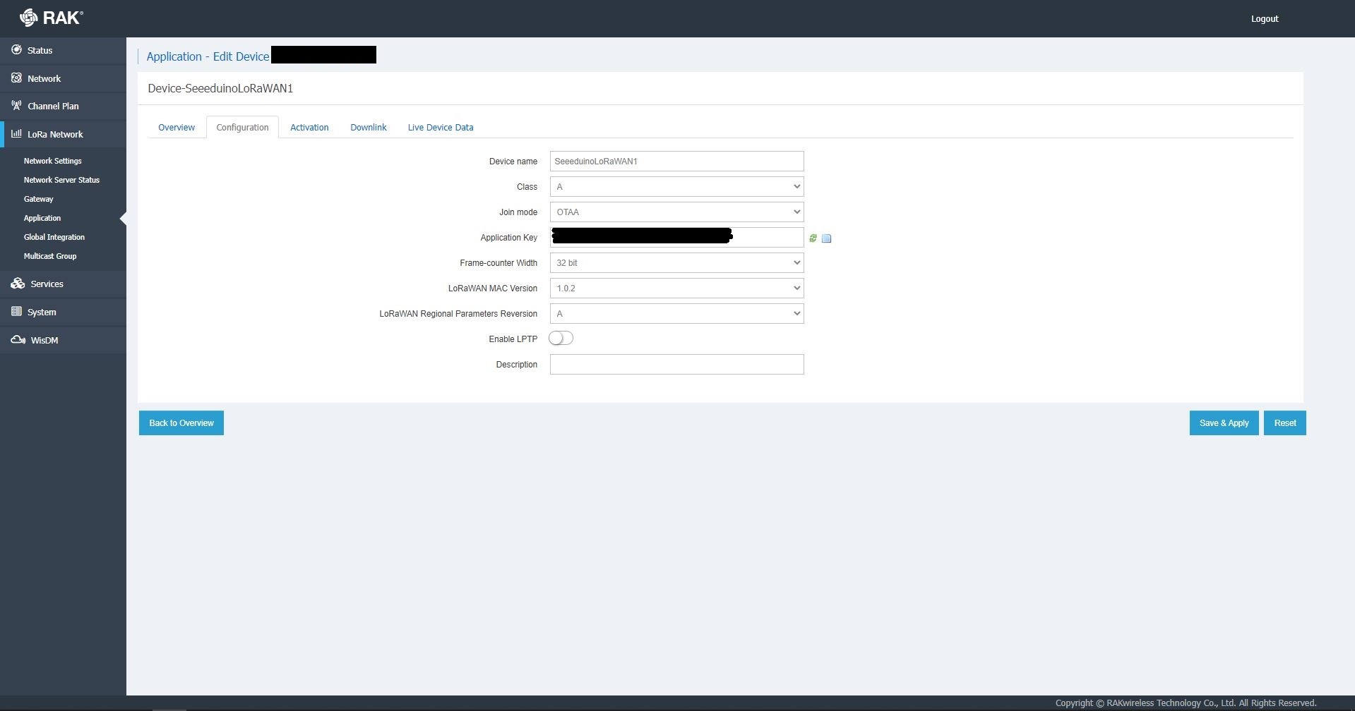
RAK 7258 Network Server Separate Application device basic setup
RAK 7258 Network Server Unified Application device basic setup
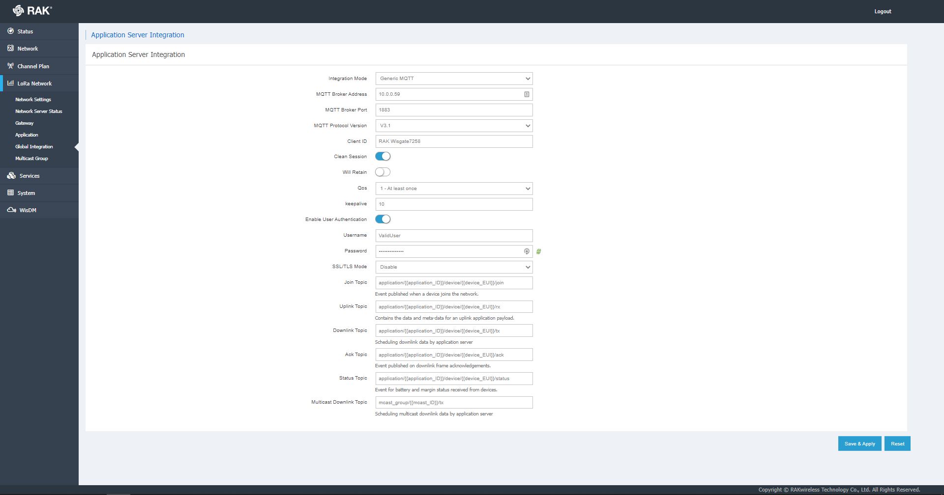
Applications also have configurable payload formats(raw & LPP) and integrations (uplink messages plus join, ack, and device notifications etc.)
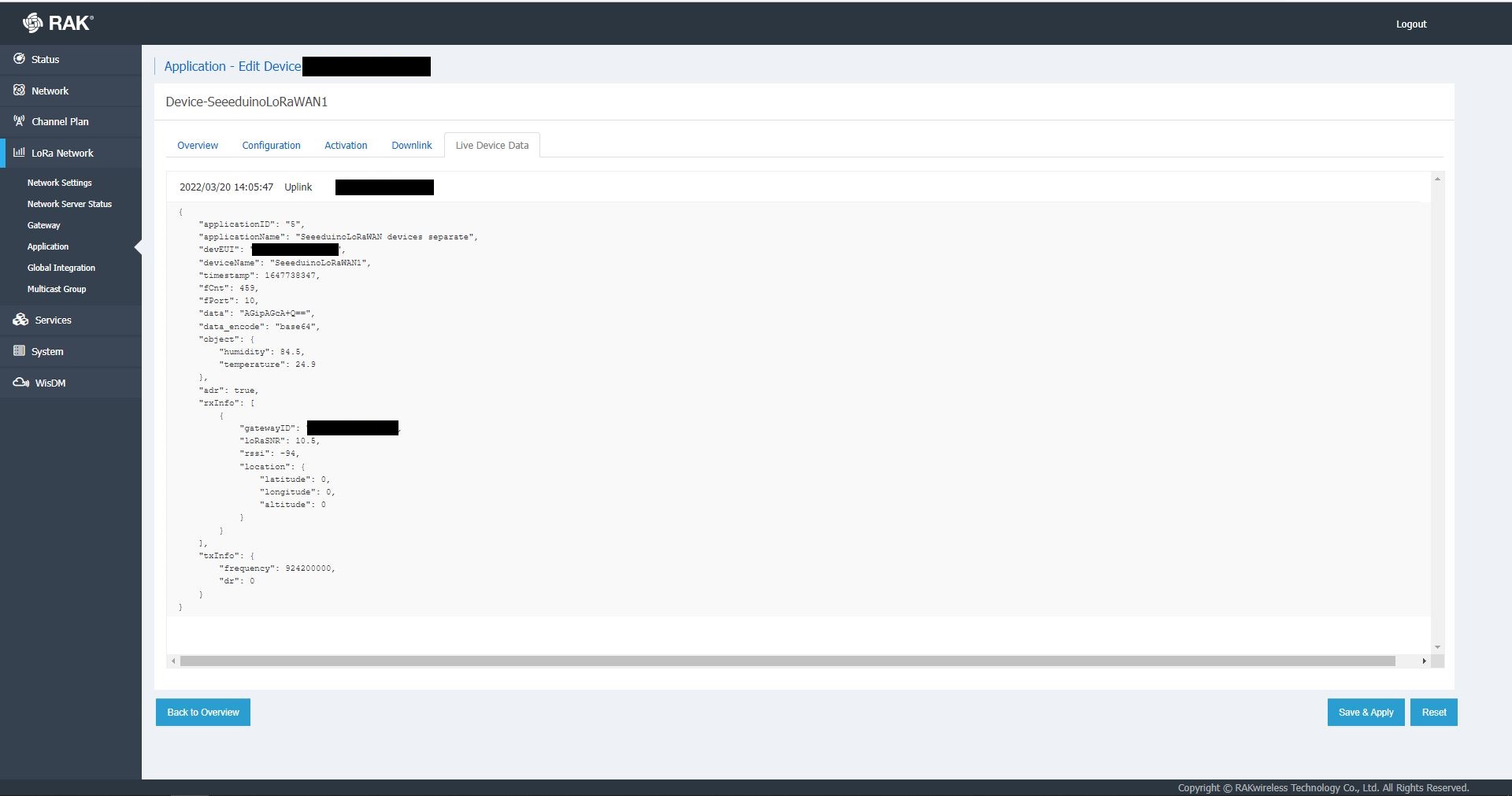
RAK7258 live device data display
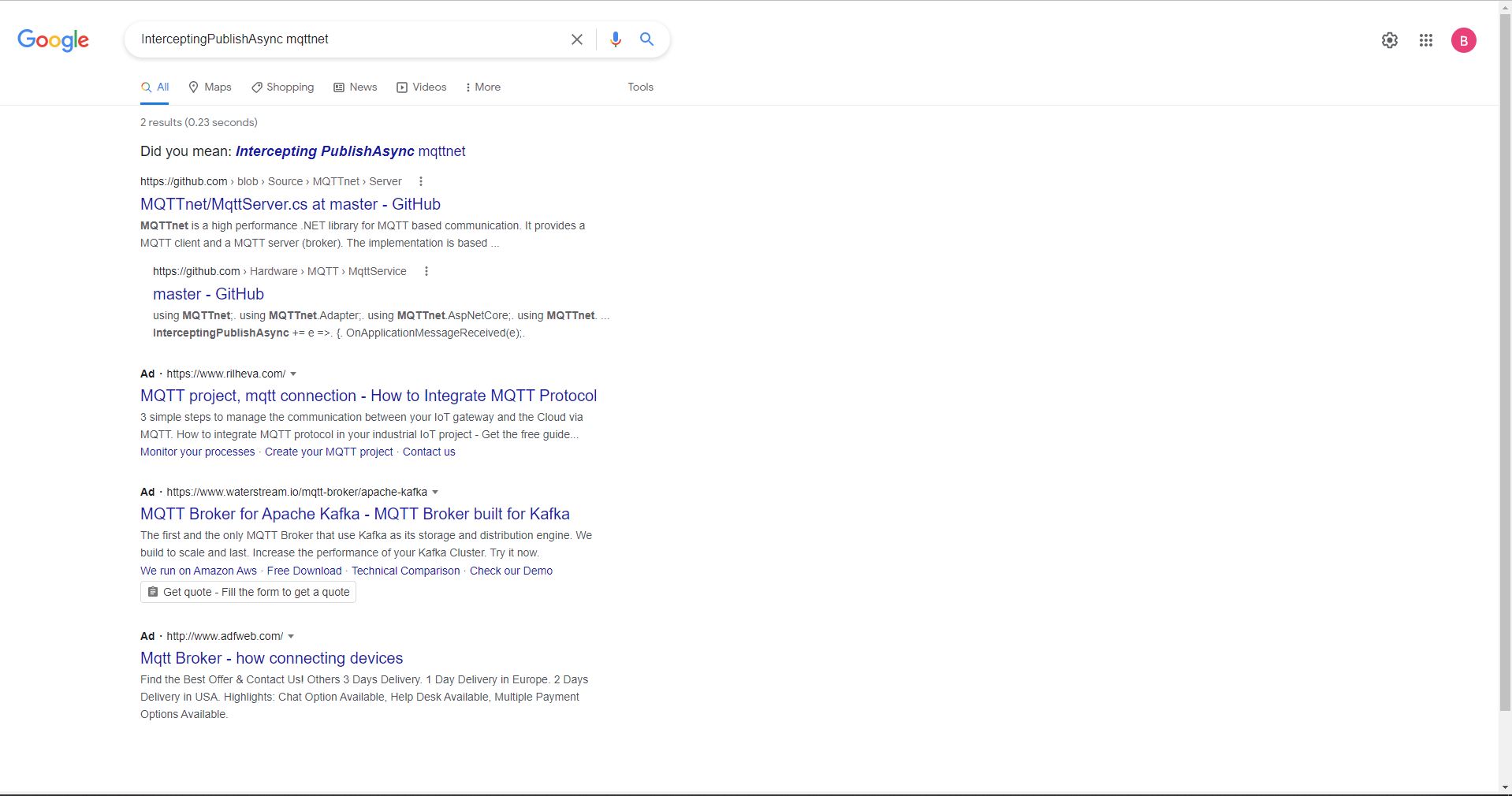
In the sample server I could see how ValidatingConnectionAsync was used to check the clientID, username and password when a device connected. I just wanted to display messages and payloads without having to use an MQTT client and it looked like InterceptingPublishAsync was a possible solution.
But the search results were a bit sparse…
InterceptingPublishAsync + MQTTNet search results
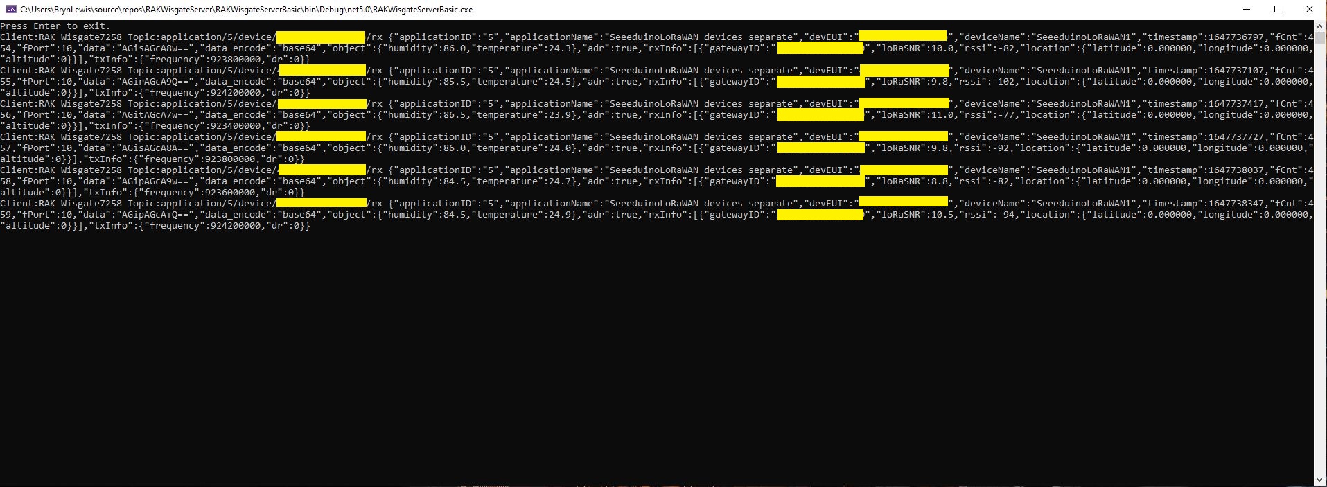
After some reading the MQTTNet documentation and some experimentation I could display the message payload (same as in the live device data display) in a “nasty” console application.
namespace devMobile.IoT.RAKWisgate.ServerBasic
{
   using System;
	using System.Threading.Tasks;

   using MQTTnet;
   using MQTTnet.Protocol;
   using MQTTnet.Server;

   public static class Program
   {
      static async Task Main(string[] args)
      {
         var mqttFactory = new MqttFactory();

         var mqttServerOptions = new MqttServerOptionsBuilder()
             .WithDefaultEndpoint()
             .Build();

         using (var mqttServer = mqttFactory.CreateMqttServer(mqttServerOptions))
         {
            mqttServer.InterceptingPublishAsync += e =>
            {
               Console.WriteLine($"Client:{e.ClientId} Topic:{e.ApplicationMessage.Topic} {e.ApplicationMessage.ConvertPayloadToString()}");

               return Task.CompletedTask;
            };

            mqttServer.ValidatingConnectionAsync += e =>
            {
               if (e.ClientId != "RAK Wisgate7258")
               {
                  e.ReasonCode = MqttConnectReasonCode.ClientIdentifierNotValid;
               }

               if (e.Username != "ValidUser")
               {
                  e.ReasonCode = MqttConnectReasonCode.BadUserNameOrPassword;
               }

               if (e.Password != "TopSecretPassword")
               {
                  e.ReasonCode = MqttConnectReasonCode.BadUserNameOrPassword;
               }

               return Task.CompletedTask;
            };

            await mqttServer.StartAsync();

            Console.WriteLine("Press Enter to exit.");
            Console.ReadLine();

            await mqttServer.StopAsync();
         }
      }
   }
}
MQTTNet based console application displaying device payloads
The process of provisioning Applications and Devices is quite different (The use of the AppEUI/JoinEUI is odd) to The Things Network(TTN) and other platforms I have used so I will explore this some more in future post(s).
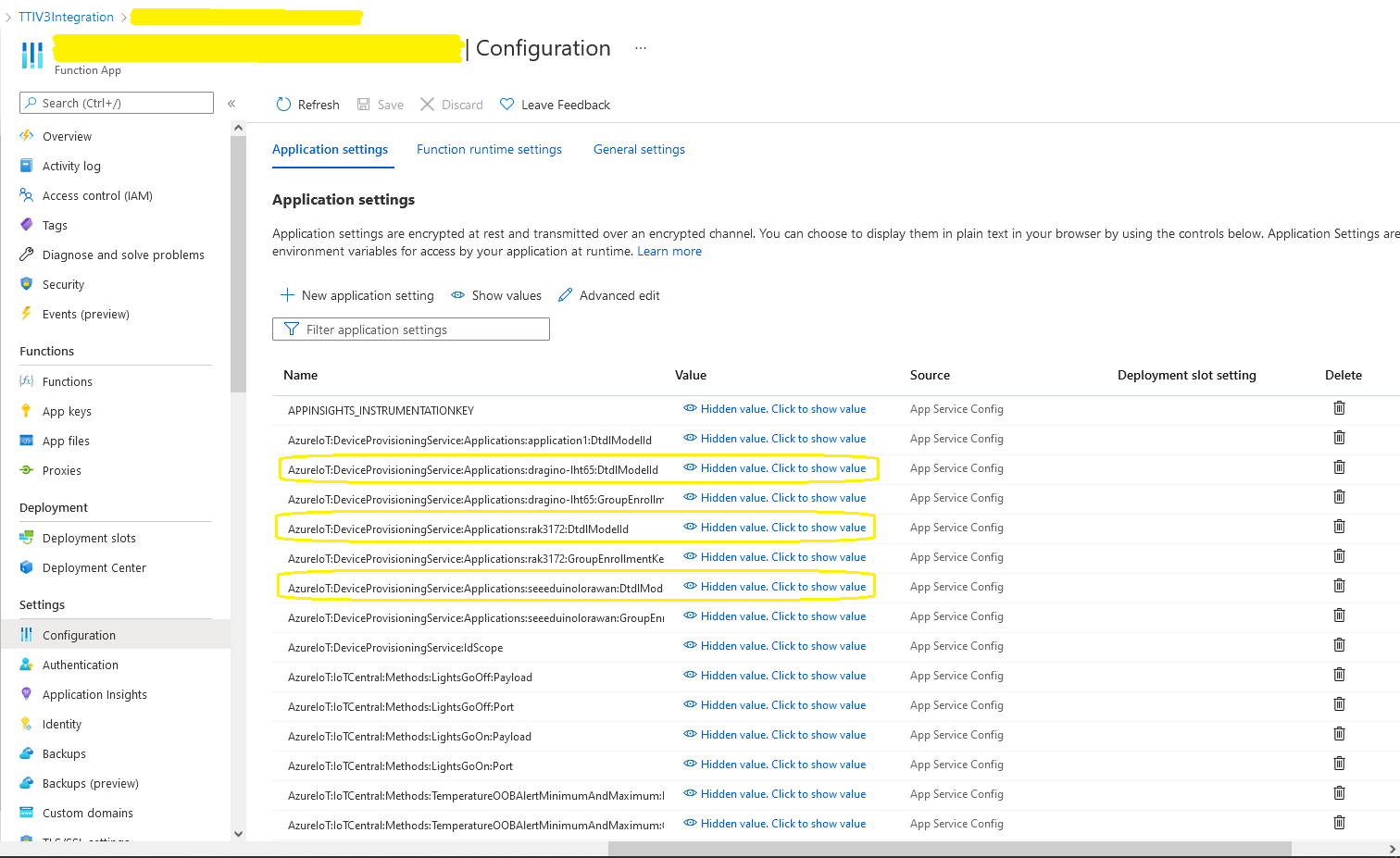
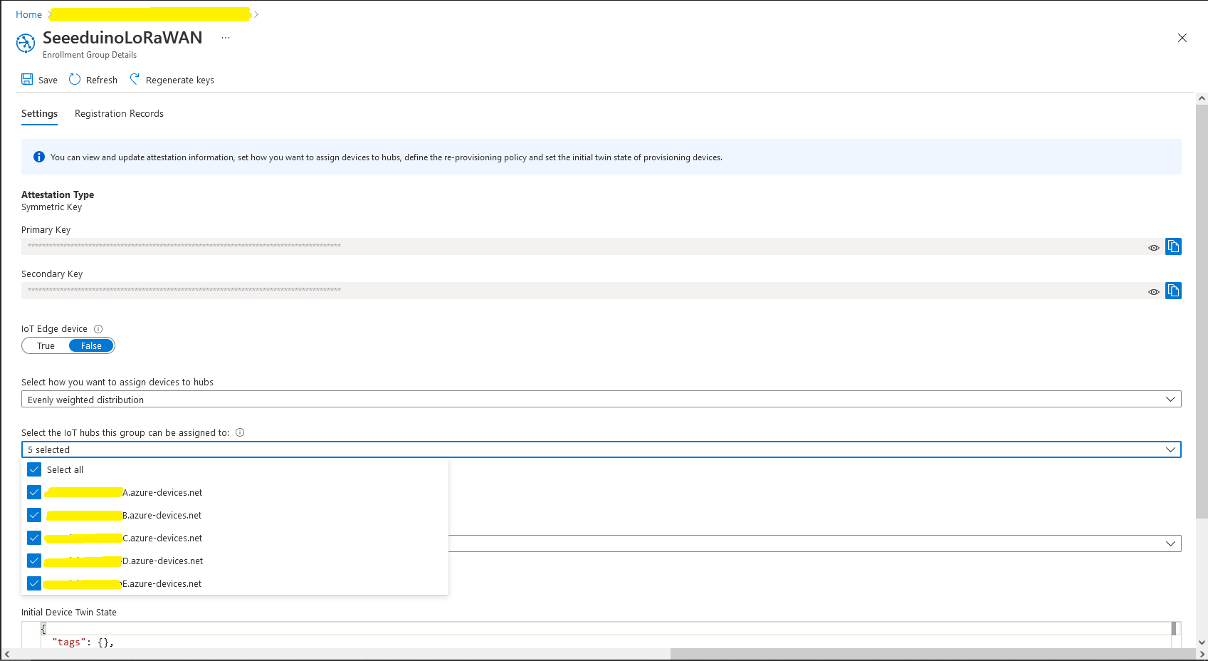
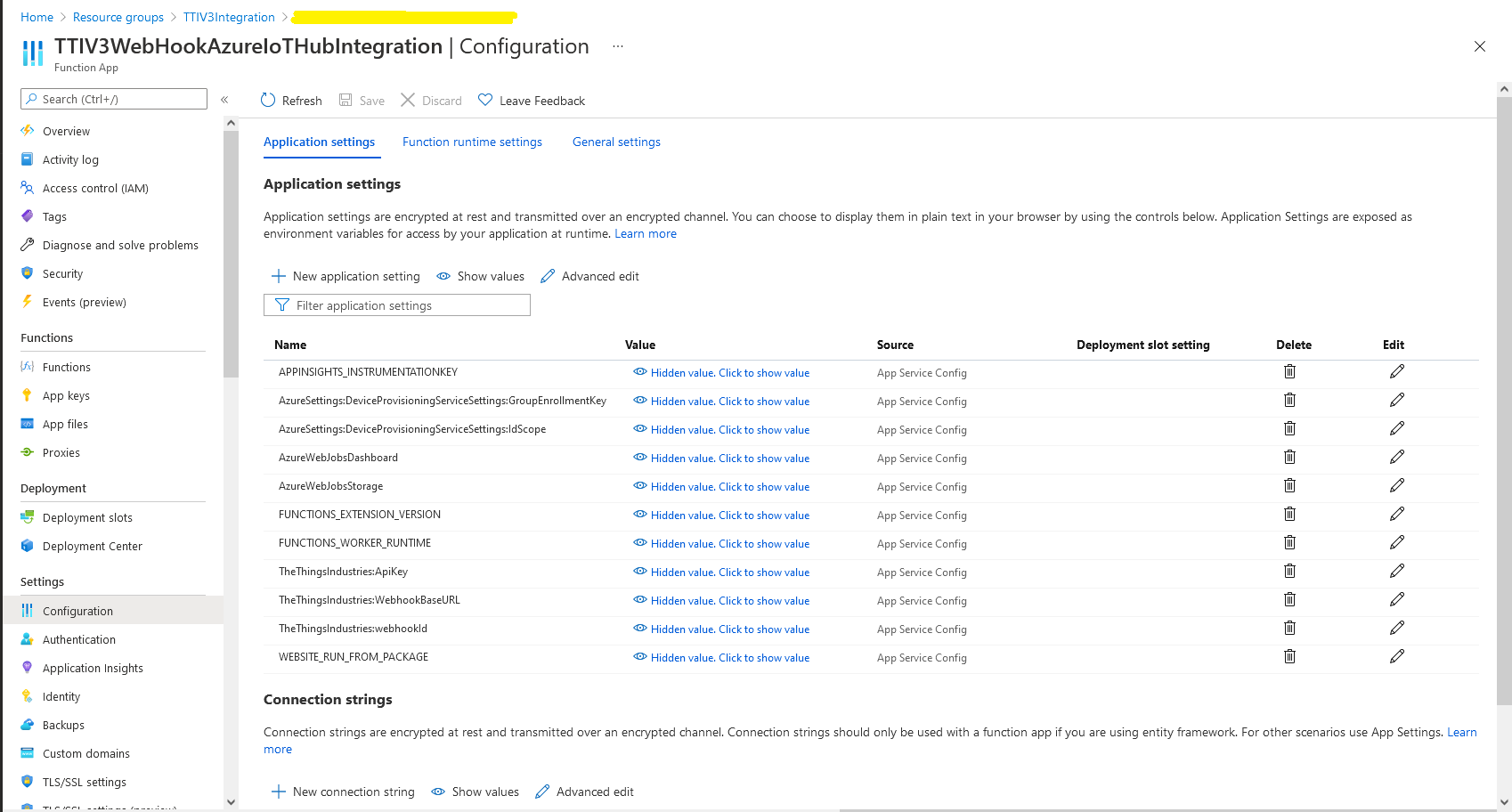
In the Azure Portal I configured the DPS ID Scope (AzureSettings:DeviceProvisioningServiceSettings:IdScope) and the Group Enrollment Key(AzureSettings:DeviceProvisioningServiceSettings:GroupEnrollmentKey) then saved the configuration which restarted the AppService.
Azure Portal AppService configration
The first time a device sent an uplink message the cache query fails and the RegisterAsync method of the ProvisioningDeviceClient is called to get a device connection string.
	logger.LogInformation("Uplink-ApplicationID:{0} DeviceID:{1} Port:{2} Payload Raw:{3}", applicationId, deviceId, port, payload.UplinkMessage.PayloadRaw);

	if (!_DeviceClients.TryGetValue(deviceId, out DeviceClient deviceClient))
	{
		logger.LogInformation("Uplink-Unknown device for ApplicationID:{0} DeviceID:{1}", applicationId, deviceId);

		// Check that only one of Azure Connection string or DPS is configured
		if (string.IsNullOrEmpty(_azureSettings.IoTHubConnectionString) && (_azureSettings.DeviceProvisioningServiceSettings == null))
		{
			logger.LogError("Uplink-Neither Azure IoT Hub connection string or Device Provisioning Service configured");

			return req.CreateResponse(HttpStatusCode.UnprocessableEntity);
		}

		// Check that only one of Azure Connection string or DPS is configured
		if (!string.IsNullOrEmpty(_azureSettings.IoTHubConnectionString) && (_azureSettings.DeviceProvisioningServiceSettings != null))
		{
			logger.LogError("Uplink-Both Azure IoT Hub connection string and Device Provisioning Service configured");

			return req.CreateResponse(HttpStatusCode.UnprocessableEntity);
		}

		// User Azure IoT Connection string if configured and Device Provisioning Service isn't
		if (!string.IsNullOrEmpty(_azureSettings.IoTHubConnectionString))
		{
			deviceClient = DeviceClient.CreateFromConnectionString(_azureSettings.IoTHubConnectionString, deviceId, transportSettings);

			try
			{
				await deviceClient.OpenAsync();
			}
			catch (DeviceNotFoundException)
			{
				logger.LogWarning("Uplink-Unknown DeviceID:{0}", deviceId);

				return req.CreateResponse(HttpStatusCode.NotFound);
			}
		}

		// Azure IoT Hub Device provisioning service if configured
		if (_azureSettings.DeviceProvisioningServiceSettings != null)
		{
			string deviceKey;

			if ( string.IsNullOrEmpty(_azureSettings.DeviceProvisioningServiceSettings.IdScope) || string.IsNullOrEmpty(_azureSettings.DeviceProvisioningServiceSettings.GroupEnrollmentKey))
			{
				logger.LogError("Uplink-Device Provisioning Service requires ID Scope and Group Enrollment Key configured");

				return req.CreateResponse(HttpStatusCode.UnprocessableEntity);
			}

			using (var hmac = new HMACSHA256(Convert.FromBase64String(_azureSettings.DeviceProvisioningServiceSettings.GroupEnrollmentKey)))
			{
				deviceKey = Convert.ToBase64String(hmac.ComputeHash(Encoding.UTF8.GetBytes(deviceId)));
			}

			using (var securityProvider = new SecurityProviderSymmetricKey(deviceId, deviceKey, null))
			{
				using (var transport = new ProvisioningTransportHandlerAmqp(TransportFallbackType.TcpOnly))
				{
					ProvisioningDeviceClient provClient = ProvisioningDeviceClient.Create(
						Constants.AzureDpsGlobalDeviceEndpoint,
						_azureSettings.DeviceProvisioningServiceSettings.IdScope,
						securityProvider,
						transport);

					DeviceRegistrationResult result = await provClient.RegisterAsync();

					if (result.Status != ProvisioningRegistrationStatusType.Assigned)
					{
						_logger.LogError("Config-DeviceID:{0} Status:{1} RegisterAsync failed ", deviceId, result.Status);

						return req.CreateResponse(HttpStatusCode.FailedDependency);
					}

					IAuthenticationMethod authentication = new DeviceAuthenticationWithRegistrySymmetricKey(result.DeviceId, (securityProvider as SecurityProviderSymmetricKey).GetPrimaryKey());

					deviceClient = DeviceClient.Create(result.AssignedHub, authentication, transportSettings);

					await deviceClient.OpenAsync();
				}
			}
		}

		if (!_DeviceClients.TryAdd(deviceId, deviceClient))
		{
			logger.LogWarning("Uplink-TryAdd failed for ApplicationID:{0} DeviceID:{1}", applicationId, deviceId);

			return req.CreateResponse(HttpStatusCode.Conflict);
		}

		Models.AzureIoTHubReceiveMessageHandlerContext context = new Models.AzureIoTHubReceiveMessageHandlerContext()
		{
			DeviceId = deviceId,
			ApplicationId = applicationId,
			WebhookId = _theThingsIndustriesSettings.WebhookId,
			WebhookBaseURL = _theThingsIndustriesSettings.WebhookBaseURL,
			ApiKey = _theThingsIndustriesSettings.ApiKey
		};

		await deviceClient.SetReceiveMessageHandlerAsync(AzureIoTHubClientReceiveMessageHandler, context);

		await deviceClient.SetMethodDefaultHandlerAsync(AzureIoTHubClientDefaultMethodHandler, context);
	}

	JObject telemetryEvent = new JObject
	{
		{ "ApplicationID", applicationId },
		{ "DeviceID", deviceId },
		{ "Port", port },
		{ "Simulated", payload.Simulated },
		{ "ReceivedAtUtc", payload.UplinkMessage.ReceivedAtUtc.ToString("s", CultureInfo.InvariantCulture) },
		{ "PayloadRaw", payload.UplinkMessage.PayloadRaw }
	};

	// If the payload has been decoded by payload formatter, put it in the message body.
	if (payload.UplinkMessage.PayloadDecoded != null)
	{
		telemetryEvent.Add("PayloadDecoded", payload.UplinkMessage.PayloadDecoded);
	}

	// Send the message to Azure IoT Hub
	using (Message ioTHubmessage = new Message(Encoding.ASCII.GetBytes(JsonConvert.SerializeObject(telemetryEvent))))
	{
		// Ensure the displayed time is the acquired time rather than the uploaded time.
		ioTHubmessage.Properties.Add("iothub-creation-time-utc", payload.UplinkMessage.ReceivedAtUtc.ToString("s", CultureInfo.InvariantCulture));
		ioTHubmessage.Properties.Add("ApplicationId", applicationId);
		ioTHubmessage.Properties.Add("DeviceEUI", payload.EndDeviceIds.DeviceEui);
		ioTHubmessage.Properties.Add("DeviceId", deviceId);
		ioTHubmessage.Properties.Add("port", port.ToString());
		ioTHubmessage.Properties.Add("Simulated", payload.Simulated.ToString());

		await deviceClient.SendEventAsync(ioTHubmessage);

		logger.LogInformation("Uplink-DeviceID:{0} SendEventAsync success", payload.EndDeviceIds.DeviceId);
	}
}
catch (Exception ex)
{
	logger.LogError(ex, "Uplink-Message processing failed");

	return req.CreateResponse(HttpStatusCode.InternalServerError);
}
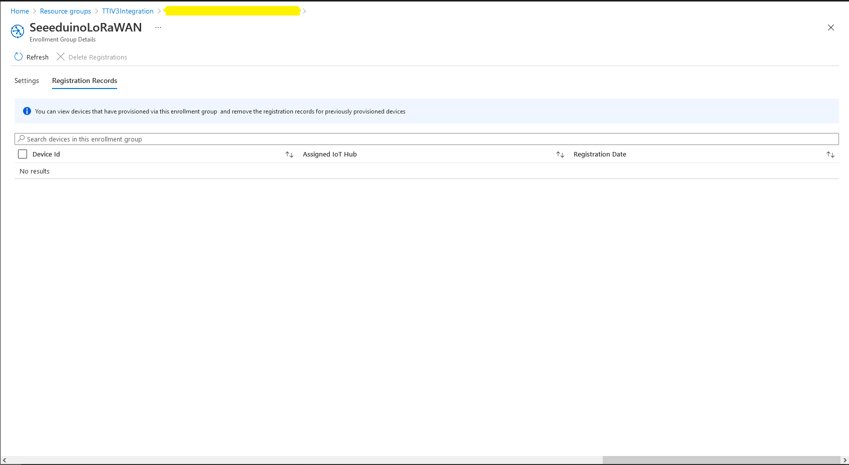
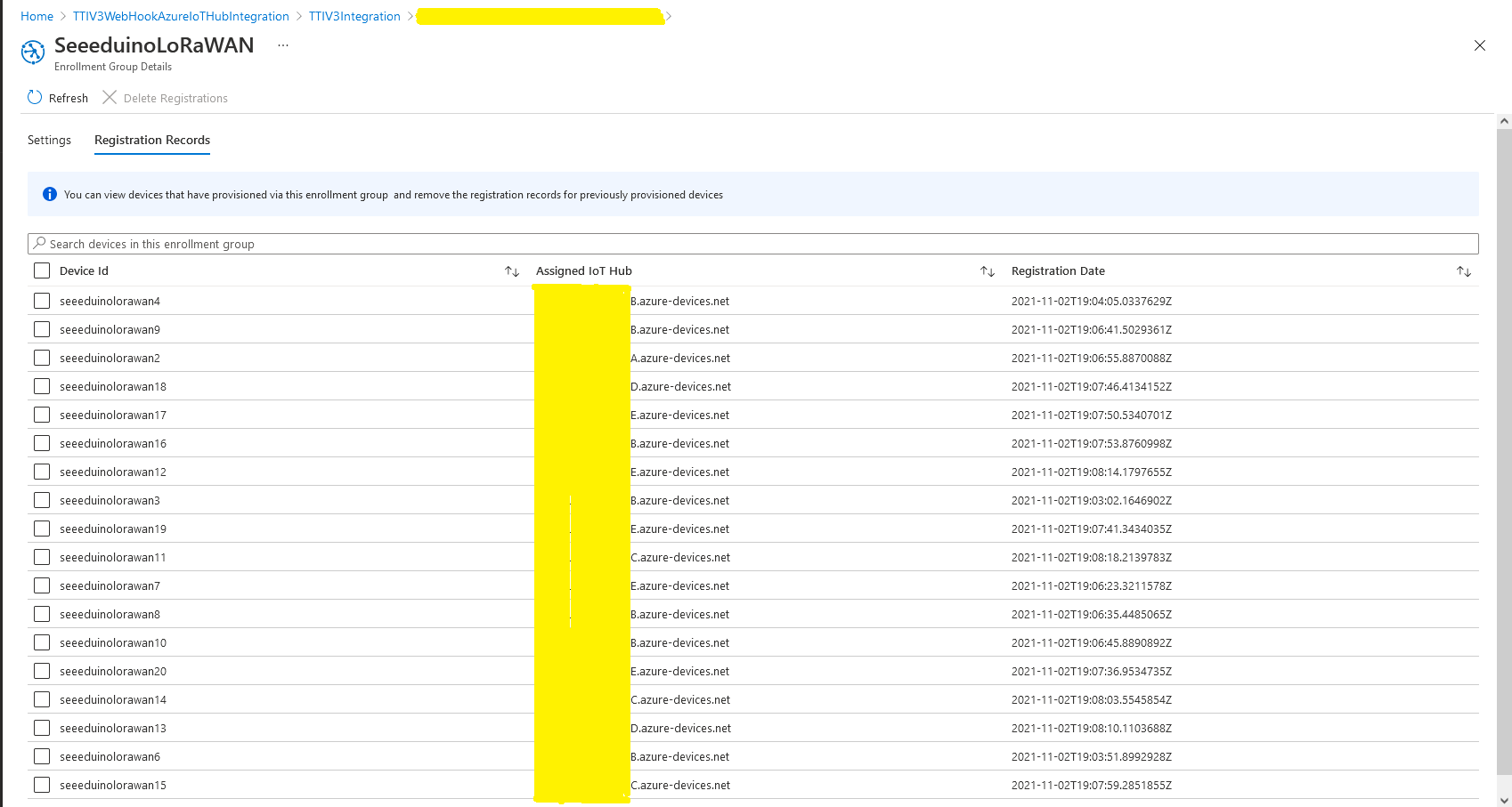
I used Telerik Fiddler and some sample payloads copied from my Azure Storage Queue sample to simulate many devices and the registrations were spread across my five Azure IoT Hubs.
DPS Device Registrations tab showing distribution of LoRaWAN Devices
I need to review the HTTP Error codes returned for different errors and ensure failures are handled robustly.