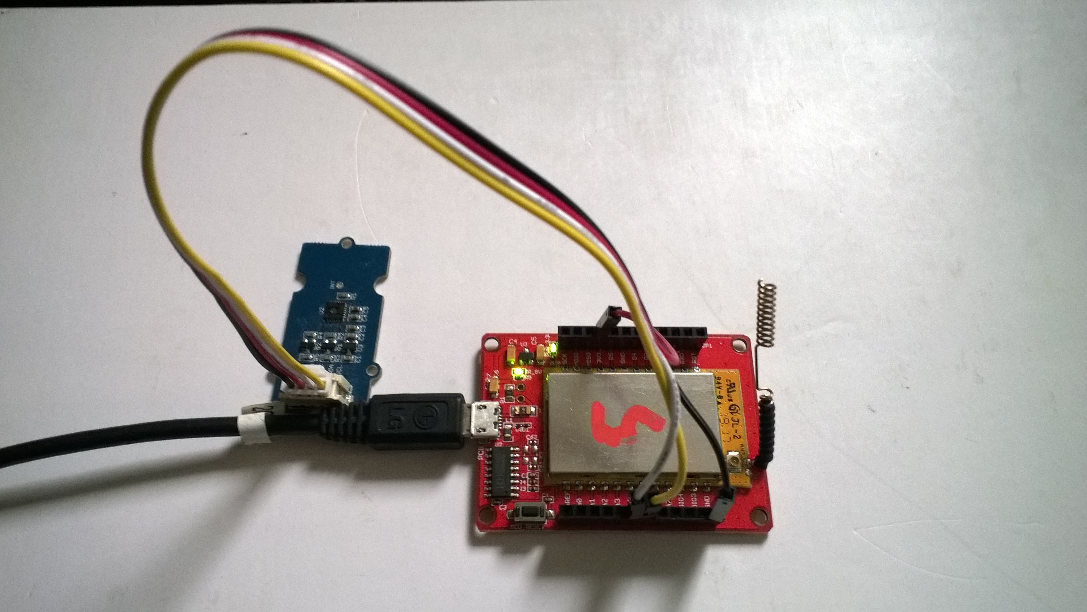
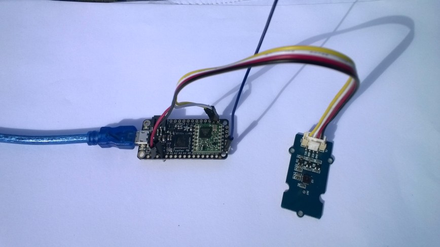
This is a demo AdaFruit Feather Mo0 Radio with LoRa Radio Module client (based on one of the examples from Arduino-LoRa) that uploads telemetry data to my Windows 10 IoT Core on Raspberry PI field gateway proof of concept(PoC).
The Adafruit learn site had sample code based on the RadioHead library which was useful. This device supports 868MHz & 915Mz, there is are other Arduino 32u4 and 433MHz devices available.
Bill of materials (Prices Sep 2018)
- Adafruit Feather M0 RFM95 LoRa Radio (433 or 900 MHz) USD34.95
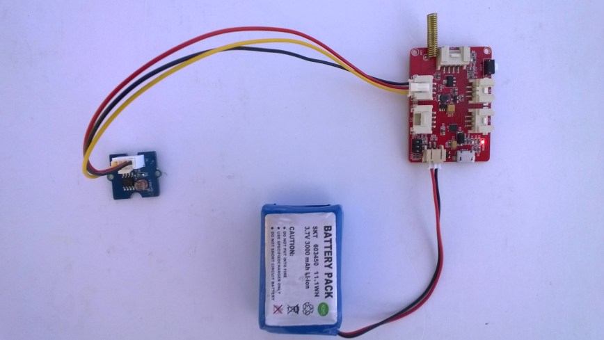
- Seeedstudio Temperature and Humidity Sensor Pro USD11.50
- Seeedstudio 4 pin Male Jumper to Grove 4 pin Conversion Cable USD2.90
The code is pretty basic, it reads a value from the Seeedstudio temperature and humidity sensor, then packs the payload and sets the necessary RFM9X/SX127X LoRa module configuration, has no power conservation, advanced wireless configuration etc. I had to add an extra include from the dstrtof function
/* Adapted from LoRa Duplex communication with Sync Word Sends temperature & humidity data from Seeedstudio https://www.seeedstudio.com/Grove-Temperature-Humidity-Sensor-High-Accuracy-Min-p-1921.html To my Windows 10 IoT Core RFM 9X libraryRFM9X.IoTCore Payload Addressing*/ #include #include #include #include const int csPin = 8; // LoRa radio chip select const int resetPin = 4; // LoRa radio reset const int irqPin = 3; // change for your board; must be a hardware interrupt pin // Field gateway configuration const char FieldGatewayAddress[] = "LoRaIoT1"; const float FieldGatewayFrequency = 915000000.0; const byte FieldGatewaySyncWord = 0x12 ; // Payload configuration const int PayloadSizeMaximum = 64 ; byte payload[PayloadSizeMaximum] = ""; const byte SensorReadingSeperator = ',' ; // Manual serial number configuration const char DeviceId[] = {"AdafruitM0"}; const int LoopSleepDelaySeconds = 10 ; void setup() { Serial.begin(9600); //while (!Serial); Serial.println("LoRa Setup"); // override the default CS, reset, and IRQ pins (optional) LoRa.setPins(csPin, resetPin, irqPin);// set CS, reset, IRQ pin if (!LoRa.begin(FieldGatewayFrequency)) { Serial.println("LoRa init failed. Check your connections."); while (true); } // Need to do this so field gateways pays attention to messages from this device LoRa.enableCrc(); LoRa.setSyncWord(FieldGatewaySyncWord); //LoRa.dumpRegisters(Serial); Serial.println("LoRa Setup done."); // Configure the Seeedstudio TH02 temperature & humidity sensor Serial.println("TH02 setup"); TH02.begin(); delay(100); Serial.println("TH02 Setup done"); Serial.println("Setup done"); } void loop() { int payloadLength = 0 ; float temperature ; float humidity ; Serial.println("Loop called"); memset(payload, 0, sizeof(payload)); // prepare the payload header with "To" Address length (top nibble) and "From" address length (bottom nibble) payload[0] = (strlen(FieldGatewayAddress) << 4) | strlen( DeviceId ) ; payloadLength += 1; // Copy the "To" address into payload memcpy(&payload[payloadLength], FieldGatewayAddress, strlen(FieldGatewayAddress)); payloadLength += strlen(FieldGatewayAddress) ; // Copy the "From" into payload memcpy(&payload[payloadLength], DeviceId, strlen(DeviceId)); payloadLength += strlen(DeviceId) ; // Read the temperature and humidity values then display nicely temperature = TH02.ReadTemperature(); humidity = TH02.ReadHumidity(); Serial.print("T:"); Serial.print( temperature, 1 ) ; Serial.print( "C" ) ; Serial.print(" H:"); Serial.print( humidity, 0 ) ; Serial.println( "%" ) ; // Copy the temperature into the payload payload[ payloadLength] = 't'; payloadLength += 1 ; payload[ payloadLength] = ' '; payloadLength += 1 ; payloadLength += strlen( dtostrf(temperature, -1, 1, (char*)&payload[payloadLength])); payload[ payloadLength] = SensorReadingSeperator; payloadLength += sizeof(SensorReadingSeperator) ; // Copy the humidity into the payload payload[ payloadLength] = 'h'; payloadLength += 1 ; payload[ payloadLength] = ' '; payloadLength += 1 ; payloadLength += strlen( dtostrf(humidity, -1, 0, (char *)&payload[payloadLength])); // display info about payload then send it (No ACK) with LoRa unlike nRF24L01 Serial.print( "RFM9X/SX127X Payload length:"); Serial.print( payloadLength ); Serial.println( " bytes" ); LoRa.beginPacket(); LoRa.write( payload, payloadLength ); LoRa.endPacket(); Serial.println("Loop done"); delay(LoopSleepDelaySeconds * 1000l); }
In the Arduino debug monitor the messages from the device looked like this
Loop done
Loop called
T:17.5C H:94%
RFM9X/SX127X Payload length:30 bytes
Loop done
Loop called
T:17.5C H:95%
RFM9X/SX127X Payload length:30 bytes
Loop done
Loop called
T:17.6C H:95%
RFM9X/SX127X Payload length:30 bytes
Loop done
In the debug output window the messages from the device looked like this
The thread 0xf9c has exited with code 0 (0x0).
The thread 0x8ac has exited with code 0 (0x0).
09:53:53-RX From AdafruitM0 PacketSnr 10.3 Packet RSSI -51dBm RSSI -103dBm = 11 byte message "t 17.8,h 93"
Sensor AdafruitM0t Value 17.8
Sensor AdafruitM0h Value 93
AzureIoTHubClient SendEventAsync start
AzureIoTHubClient SendEventAsync finish
The thread 0x704 has exited with code 0 (0x0).
The thread 0xad4 has exited with code 0 (0x0).
09:54:03-RX From AdafruitM0 PacketSnr 9.8 Packet RSSI -52dBm RSSI -101dBm = 11 byte message "t 17.8,h 93"
Sensor AdafruitM0t Value 17.8
Sensor AdafruitM0h Value 93
AzureIoTHubClient SendEventAsync start
AzureIoTHubClient SendEventAsync finish
The thread 0x1084 has exited with code 0 (0x0).
The thread 0xa2c has exited with code 0 (0x0).
09:54:14-RX From AdafruitM0 PacketSnr 9.8 Packet RSSI -54dBm RSSI -102dBm = 11 byte message "t 17.7,h 93"
Sensor AdafruitM0t Value 17.7
Sensor AdafruitM0h Value 93
AzureIoTHubClient SendEventAsync start
AzureIoTHubClient SendEventAsync finish
The thread 0x1720 has exited with code 0 (0x0).
…
10:00:06-RX From AdafruitM0 PacketSnr 9.3 Packet RSSI -52dBm RSSI -100dBm = 12 byte message "t 184.0,h 91"
Sensor AdafruitM0t Value 184.0
Sensor AdafruitM0h Value 91
AzureIoTHubClient SendEventAsync start
AzureIoTHubClient SendEventAsync finish
The thread 0x15d4 has exited with code 0 (0x0).
The thread 0x15f4 has exited with code 0 (0x0).
10:00:19-RX From AdafruitM0 PacketSnr 10.0 Packet RSSI -48dBm RSSI -102dBm = 12 byte message "t 180.9,h 94"
Sensor AdafruitM0t Value 180.9
Sensor AdafruitM0h Value 94
AzureIoTHubClient SendEventAsync start
AzureIoTHubClient SendEventAsync finish
The thread 0xabc has exited with code 0 (0x0).
The thread 0x2e4 has exited with code 0 (0x0).
10:00:29-RX From AdafruitM0 PacketSnr 9.8 Packet RSSI -49dBm RSSI -102dBm = 12 byte message "t -50.0,h 94"
Sensor AdafruitM0t Value -50.0
Sensor AdafruitM0h Value 94
AzureIoTHubClient SendEventAsync start
AzureIoTHubClient SendEventAsync finish
The thread 0x950 has exited with code 0 (0x0).
The thread 0x145c has exited with code 0 (0x0).
The thread 0x176c has exited with code 0 (0x0).
10:00:39-RX From AdafruitM0 PacketSnr 9.5 Packet RSSI -50dBm RSSI -102dBm = 11 byte message "t 17.5,h 94"
Sensor AdafruitM0t Value 17.5
Sensor AdafruitM0h Value 94
AzureIoTHubClient SendEventAsync start
AzureIoTHubClient SendEventAsync finish
The thread 0x165c has exited with code 0 (0x0).
The thread 0x6e8 has exited with code 0 (0x0).
10:00:49-RX From AdafruitM0 PacketSnr 9.8 Packet RSSI -59dBm RSSI -100dBm = 11 byte message "t 17.5,h 95"
Sensor AdafruitM0t Value 17.5
Sensor AdafruitM0h Value 95
AzureIoTHubClient SendEventAsync start
AzureIoTHubClient SendEventAsync finish
The thread 0x1334 has exited with code 0 (0x0).
The thread 0x14d0 has exited with code 0 (0x0).
10:00:59-RX From AdafruitM0 PacketSnr 9.5 Packet RSSI -66dBm RSSI -102dBm = 11 byte message "t 17.6,h 95"
Sensor AdafruitM0t Value 17.6
Sensor AdafruitM0h Value 95
AzureIoTHubClient SendEventAsync start
AzureIoTHubClient SendEventAsync finish
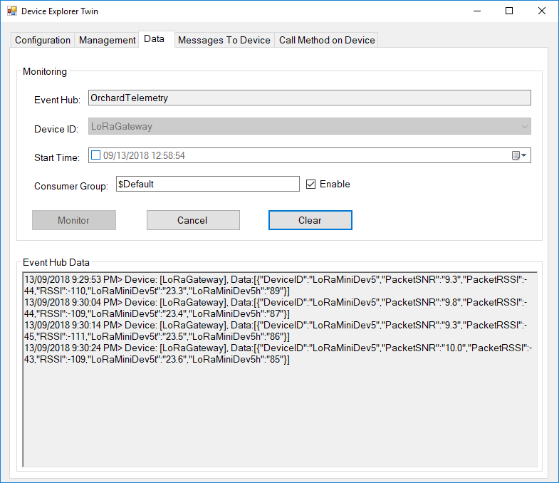
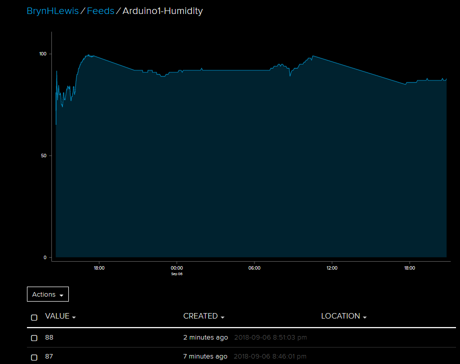
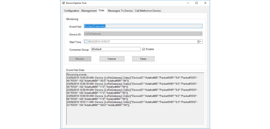
Then at my Azure IoT hub the data stream looked like this
To reduce power consumption I would disconnect/remove the light emitting diode(LED)