.NET Core 5 Raspberry PI SPI

I have spent a lot of time debugging Serial Peripheral Interface(SPI) device libraries and the .Net Core 5 dotnet/iot library will have its own subtleties(with SPI it’s all about timing). I have written GHI Electronics TinyCLR, Wilderness Labs Meadow, Windows 10 IoT Core, .NET MicroFramework and .NET nanoFramework libraries the SX127X family of devices so building a .Net Core 5 one seemed like a good place to start.

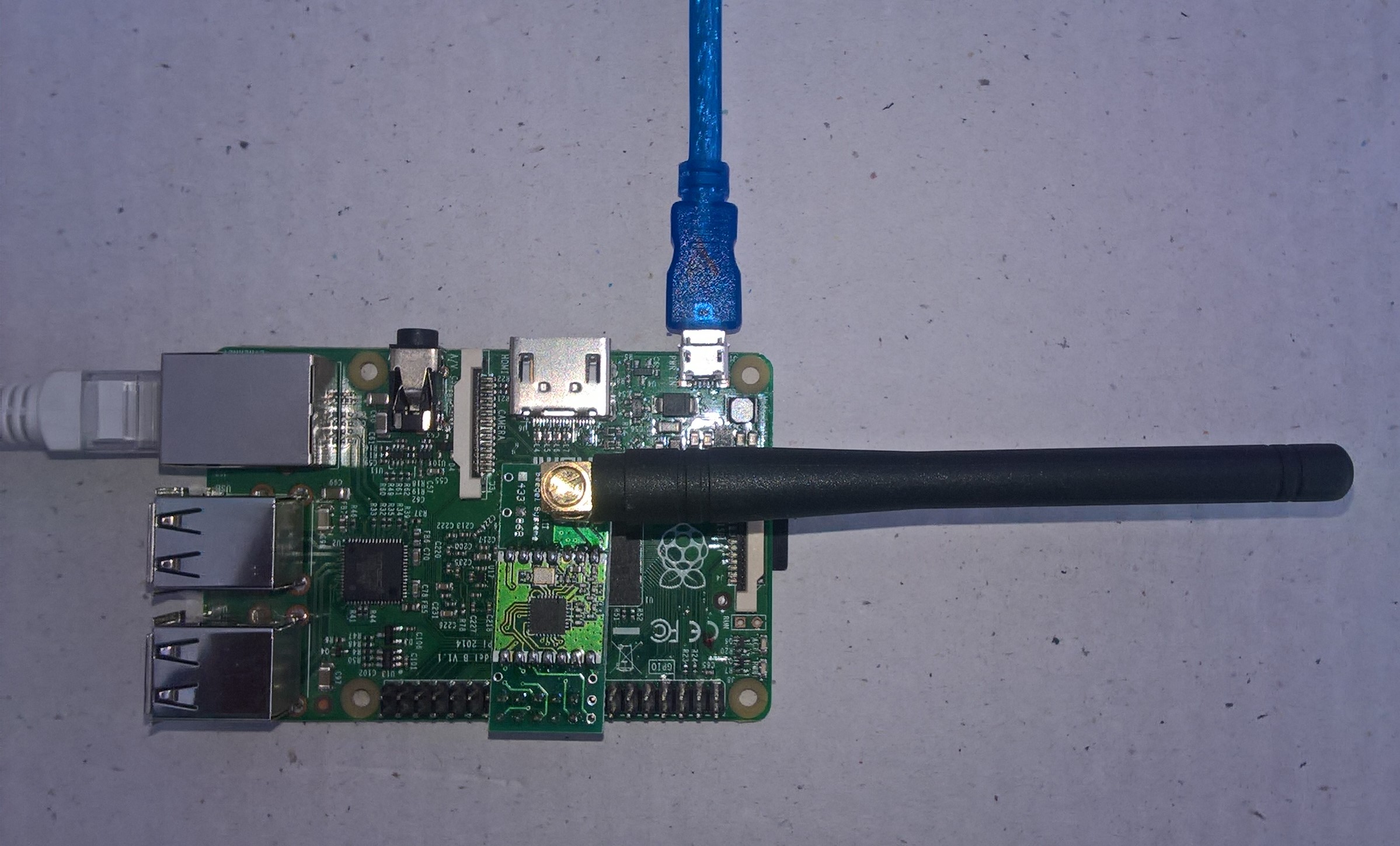
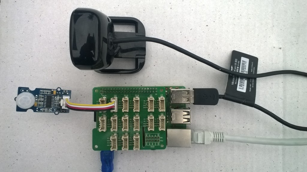
I’m using a Uputronics Raspberry PiZero LoRa(TM) Expansion Board which supports both standard Chip Select(CS) pins (switch selectable which is really useful) and an M2M 1 Channel LoRaWan Gateway Shield for Raspberry PI which has a “non-standard” CS pin.

Uputronics Raspberry PIZero LoRa Expansion board on a Raspberry 3 device

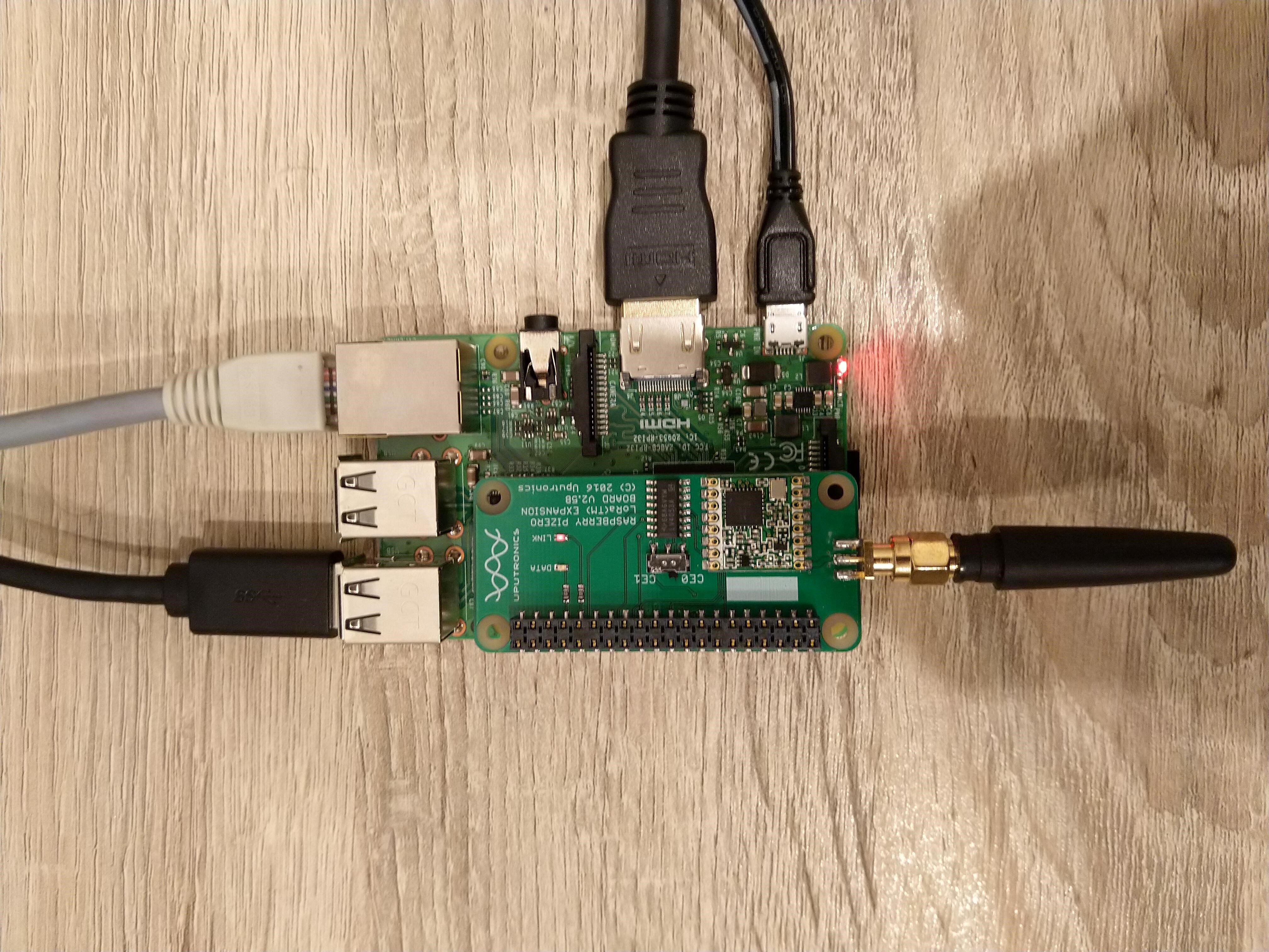
The Uputronics pHat has a pair of Light Emitting Diodes(LEDs) so I adapted some code from a previous post to flash these to confirm the card was working.

static void UputronicsLeds()
{
	const int RedLedPinNumber = 6;
	const int GreenLedPinNumber = 13;

	GpioController controller = new GpioController(PinNumberingScheme.Logical);

	controller.OpenPin(RedLedPinNumber, PinMode.Output);
	controller.OpenPin(GreenLedPinNumber, PinMode.Output);

	while (true)
	{
		if (controller.Read(RedLedPinNumber) == PinValue.Low)
		{
			controller.Write(RedLedPinNumber, PinValue.High);
			controller.Write(GreenLedPinNumber, PinValue.Low);
		}
		else
		{
			controller.Write(RedLedPinNumber, PinValue.Low);
			controller.Write(GreenLedPinNumber, PinValue.High);
		}

		Thread.Sleep(1000);
	}
}

The first Uputronics pHat version using spiDevice.TransferFullDuplex didn’t work. I tried allocating memory for the buffers with new and stackalloc which didn’t seem to make any difference in my trivial example. I tried different Chip Select(CS) pin options, frequencies and modes (the mode used is based on the timings specified in the SX127X datasheet).

static void TransferFullDuplex()
{
	//byte[] writeBuffer = new byte[1]; // Memory allocation didn't seem to make any difference
    //byte[] readBuffer = new byte[1];
	Span<byte> writeBuffer = stackalloc byte[1];
	Span<byte> readBuffer = stackalloc byte[1];

	//var settings = new SpiConnectionSettings(0)
	var settings = new SpiConnectionSettings(0, 0)
	//var settings = new SpiConnectionSettings(0, 1)
	{
		ClockFrequency = 5000000,
		//ClockFrequency = 500000, // Frequency didn't seem to make any difference
		Mode = SpiMode.Mode0,   // From SemTech docs pg 80 CPOL=0, CPHA=0
	};

	SpiDevice spiDevice = SpiDevice.Create(settings);

	Thread.Sleep(500);

	while (true)
	{
		try
		{
			for (byte registerIndex = 0; registerIndex <= 0x42; registerIndex++)
			{
				writeBuffer[0] = registerIndex;
				spiDevice.TransferFullDuplex(writeBuffer, readBuffer);
				//Debug.WriteLine("Register 0x{0:x2} - Value 0X{1:x2} - Bits {2}", writeBuffer[0], readBuffer[0], Convert.ToString(readBuffer[0], 2).PadLeft(8, '0')); // Debug output stopped after roughly 3 times round for loop often debugger would barf as well
				Console.WriteLine("Register 0x{0:x2} - Value 0X{1:x2} - Bits {2}", writeBuffer[0], readBuffer[0], Convert.ToString(readBuffer[0], 2).PadLeft(8, '0'));

				// Would be nice if SpiDevice has a TransferSequential
				/* 
				writeBuffer[0] = registerIndex;
				spiDevice.TransferSequential(writeBuffer, readBuffer);
				Console.WriteLine("Register 0x{0:x2} - Value 0X{1:x2} - Bits {2}", writeBuffer[0], readBuffer[0], Convert.ToString(readBuffer[0], 2).PadLeft(8, '0'));
				*/
			}

			Console.WriteLine("");
			Thread.Sleep(5000);
		}
		catch (Exception ex)
		{
			Console.WriteLine(ex.Message);
		}
	}
}

The second Uputronics pHat version using spiDevice.ReadByte() and spiDevice.WriteBye() didn’t work either.

static void ReadWriteChipSelectStandard()
{
	var settings = new SpiConnectionSettings(0) // Doesn't work
	//	var settings = new SpiConnectionSettings(0, 0) // Doesn't work
	//var settings = new SpiConnectionSettings(0, 1) // Doesn't Work
	{
		ClockFrequency = 5000000,
		ChipSelectLineActiveState = PinValue.Low,
		Mode = SpiMode.Mode0,   // From SemTech docs pg 80 CPOL=0, CPHA=0
	};

	SpiDevice spiDevice = SpiDevice.Create(settings);

	Thread.Sleep(500);

	while (true)
	{
		try
		{
			for (byte registerIndex = 0; registerIndex <= 0x42; registerIndex++)
			{
				spiDevice.WriteByte(registerIndex);
				//Thread.Sleep(5); These made no difference
				//Thread.Sleep(10);
				//Thread.Sleep(20);
				//Thread.Sleep(40);
				byte registerValue = spiDevice.ReadByte();

				Console.WriteLine("Register 0x{0:x2} - Value 0X{1:x2} - Bits {2}", registerIndex, registerValue, Convert.ToString(registerValue, 2).PadLeft(8, '0'));
			}
			Console.WriteLine("");

			Thread.Sleep(5000);
		}
		catch (Exception ex)
		{
			Console.WriteLine(ex.Message);
		}
	}
}

The third Uputronics pHat version using spiDevice.ReadByte() and spiDevice.WriteByte() with DIY Chip Select(CS) worked. In previous SPI device libraries I have found that “managing” the CS line in code can be easier to get working The MicroFramework also has more connectionSettings options for better control of CS line timings which reduces the need for DIY.

static void ReadWriteChipSelectDiy()
{
	const int CSPinNumber = 8; // CS0
	//const int CSPinNumber = 7; // CS1

	// DIY CS0 implented with GPIO pin application controls
	GpioController controller = new GpioController(PinNumberingScheme.Logical);

	controller.OpenPin(CSPinNumber, PinMode.Output);
	//controller.Write(CSPinNumber, PinValue.High);

	//var settings = new SpiConnectionSettings(0) // Doesn't work
	var settings = new SpiConnectionSettings(0, 1) // Works, have to point at unused CS1, this could be a problem is other device on CS1
	//var settings = new SpiConnectionSettings(0, 0) // Works, have to point at unused CS0, this could be a problem is other device on CS0
	{
		ClockFrequency = 5000000,
		Mode = SpiMode.Mode0,   // From SemTech docs pg 80 CPOL=0, CPHA=0
	};

	SpiDevice spiDevice = SpiDevice.Create(settings);

	Thread.Sleep(500);

	while (true)
	{
		try
		{
			for (byte registerIndex = 0; registerIndex <= 0x42; registerIndex++)
			{
				controller.Write(CSPinNumber, PinValue.Low);
				spiDevice.WriteByte(registerIndex);
				//Thread.Sleep(2); // This maybe necessary
				byte registerValue = spiDevice.ReadByte();
				controller.Write(CSPinNumber, PinValue.High);

				Console.WriteLine("Register 0x{0:x2} - Value 0X{1:x2} - Bits {2}", registerIndex, registerValue, Convert.ToString(registerValue, 2).PadLeft(8, '0'));
			}
			Console.WriteLine("");

			Thread.Sleep(5000);
		}
		catch (Exception ex)
		{
			Console.WriteLine(ex.Message);
		}
	}
}

The dotNet/IoT doesn’t support (July2021) the option to “exclusively” open a port so there could be issues with other applications assuming they control CS0/CS1.

Loaded '/usr/lib/dotnet/shared/Microsoft.NETCore.App/5.0.4/Microsoft.Win32.Primitives.dll'. Skipped loading symbols. Module is optimized and the debugger option 'Just My Code' is enabled.
Register 0x00 - Value 0X00 - Bits 00000000
Register 0x01 - Value 0X09 - Bits 00001001
Register 0x02 - Value 0X1a - Bits 00011010
Register 0x03 - Value 0X0b - Bits 00001011
Register 0x04 - Value 0X00 - Bits 00000000
Register 0x05 - Value 0X52 - Bits 01010010
Register 0x06 - Value 0X6c - Bits 01101100
Register 0x07 - Value 0X80 - Bits 10000000
Register 0x08 - Value 0X00 - Bits 00000000
Register 0x09 - Value 0X4f - Bits 01001111
Register 0x0a - Value 0X09 - Bits 00001001
Register 0x0b - Value 0X2b - Bits 00101011
Register 0x0c - Value 0X20 - Bits 00100000
Register 0x0d - Value 0X08 - Bits 00001000
Register 0x0e - Value 0X02 - Bits 00000010
Register 0x0f - Value 0X0a - Bits 00001010
Register 0x10 - Value 0Xff - Bits 11111111
Register 0x11 - Value 0X70 - Bits 01110000
Register 0x12 - Value 0X15 - Bits 00010101
Register 0x13 - Value 0X0b - Bits 00001011
Register 0x14 - Value 0X28 - Bits 00101000
Register 0x15 - Value 0X0c - Bits 00001100
Register 0x16 - Value 0X12 - Bits 00010010
Register 0x17 - Value 0X47 - Bits 01000111
Register 0x18 - Value 0X32 - Bits 00110010
Register 0x19 - Value 0X3e - Bits 00111110
Register 0x1a - Value 0X00 - Bits 00000000
Register 0x1b - Value 0X00 - Bits 00000000
Register 0x1c - Value 0X00 - Bits 00000000
Register 0x1d - Value 0X00 - Bits 00000000
Register 0x1e - Value 0X00 - Bits 00000000
Register 0x1f - Value 0X40 - Bits 01000000
Register 0x20 - Value 0X00 - Bits 00000000
Register 0x21 - Value 0X00 - Bits 00000000
Register 0x22 - Value 0X00 - Bits 00000000
Register 0x23 - Value 0X00 - Bits 00000000
Register 0x24 - Value 0X05 - Bits 00000101
Register 0x25 - Value 0X00 - Bits 00000000
Register 0x26 - Value 0X03 - Bits 00000011
Register 0x27 - Value 0X93 - Bits 10010011
Register 0x28 - Value 0X55 - Bits 01010101
Register 0x29 - Value 0X55 - Bits 01010101
Register 0x2a - Value 0X55 - Bits 01010101
Register 0x2b - Value 0X55 - Bits 01010101
Register 0x2c - Value 0X55 - Bits 01010101
Register 0x2d - Value 0X55 - Bits 01010101
Register 0x2e - Value 0X55 - Bits 01010101
Register 0x2f - Value 0X55 - Bits 01010101
Register 0x30 - Value 0X90 - Bits 10010000
Register 0x31 - Value 0X40 - Bits 01000000
Register 0x32 - Value 0X40 - Bits 01000000
Register 0x33 - Value 0X00 - Bits 00000000
Register 0x34 - Value 0X00 - Bits 00000000
Register 0x35 - Value 0X0f - Bits 00001111
Register 0x36 - Value 0X00 - Bits 00000000
Register 0x37 - Value 0X00 - Bits 00000000
Register 0x38 - Value 0X00 - Bits 00000000
Register 0x39 - Value 0Xf5 - Bits 11110101
Register 0x3a - Value 0X20 - Bits 00100000
Register 0x3b - Value 0X82 - Bits 10000010
Register 0x3c - Value 0Xf6 - Bits 11110110
Register 0x3d - Value 0X02 - Bits 00000010
Register 0x3e - Value 0X80 - Bits 10000000
Register 0x3f - Value 0X40 - Bits 01000000
Register 0x40 - Value 0X00 - Bits 00000000
Register 0x41 - Value 0X00 - Bits 00000000
Register 0x42 - Value 0X12 - Bits 00010010

The fourth Uputronics pHat version using spiDevice.TransferFullDuplex with read and write buffers two bytes long and the leading bye of the response ignored worked.

...
while (true)
{
	try
	{
		for (byte registerIndex = 0; registerIndex <= 0x42; registerIndex++)
		{
			// Doesn't work
			writeBuffer[0] = registerIndex;
			spiDevice.TransferFullDuplex(writeBuffer, readBuffer);
			Console.WriteLine("Register 0x{0:x2} - Value 0X{1:x2} - Bits {2}", registerIndex, readBuffer[0], Convert.ToString(readBuffer[0], 2).PadLeft(8, '0'));

			// Does work
			writeBuffer[0] = registerIndex;
			spiDevice.TransferFullDuplex(writeBuffer, readBuffer);
			Console.WriteLine("Register 0x{0:x2} - Value 0X{1:x2} - Bits {2}", registerIndex, readBuffer[1], Convert.ToString(readBuffer[1], 2).PadLeft(8, '0'));

			// Does work
			writeBuffer[1] = registerIndex;
			spiDevice.TransferFullDuplex(writeBuffer, readBuffer);
			Console.WriteLine("Register 0x{0:x2} - Value 0X{1:x2} - Bits {2}", registerIndex, readBuffer[1], Convert.ToString(readBuffer[1], 2).PadLeft(8, '0'));

			Console.WriteLine("");
		}

		Console.WriteLine("");
		Thread.Sleep(5000);
	}
	catch (Exception ex)
	{
		Console.WriteLine(ex.Message);
	}
}

Register 0x00 - Value 0X00 - Bits 00000000

...

Register 0x42 - Value 0X00 - Bits 00000000
Register 0x42 - Value 0X12 - Bits 00010010

M2M Single channel shield on Raspberry Pi 3 Device

The first M2M pHat version using SpiDevice.Read and SpiDevice.Write with a “custom” CS pin worked.

...
// Chip select with pin which isn't CS0 or CS1 needs M2M shield
static void ReadWriteDiyChipSelectNonStandard()
{
	const int CSPinNumber = 25;

	// DIY CS0 implented with GPIO pin application controls
	GpioController controller = new GpioController(PinNumberingScheme.Logical);

	controller.OpenPin(CSPinNumber, PinMode.Output);
	//controller.Write(CSPinNumber, PinValue.High);

	// Work, this could be a problem is other device on CS0/CS1
	var settings = new SpiConnectionSettings(0)
	//var settings = new SpiConnectionSettings(0, 0) 
	//var settings = new SpiConnectionSettings(0, 1) 
	{
		ClockFrequency = 5000000,
		Mode = SpiMode.Mode0,   // From SemTech docs pg 80 CPOL=0, CPHA=0
	};

	SpiDevice spiDevice = SpiDevice.Create(settings);

	Thread.Sleep(500);

	while (true)
	{
		try
		{
			for (byte registerIndex = 0; registerIndex <= 0x42; registerIndex++)
			{
				controller.Write(CSPinNumber, PinValue.Low);
				spiDevice.WriteByte(registerIndex);
				//Thread.Sleep(2); // This maybe necessary
				byte registerValue = spiDevice.ReadByte();
				controller.Write(CSPinNumber, PinValue.High);

				Console.WriteLine("Register 0x{0:x2} - Value 0X{1:x2} - Bits {2}", registerIndex, registerValue, Convert.ToString(registerValue, 2).PadLeft(8, '0'));
			}
			Console.WriteLine("");

			Thread.Sleep(5000);
		}
		catch (Exception ex)
		{
			Console.WriteLine(ex.Message);
		}
	}
}

The second M2M pHat version using SpiDevice.TransferFullDuplex with a “custom” CS pin also worked.

while (true)
{
	try
	{
		for (byte registerIndex = 0; registerIndex <= 0x42; registerIndex++)
		{
			writeBuffer[0] = registerIndex;
			//writeBuffer[1] = registerIndex;

			controller.Write(CSPinNumber, PinValue.Low);
			spiDevice.TransferFullDuplex(writeBuffer, readBuffer);
			controller.Write(CSPinNumber, PinValue.High);

			Console.WriteLine("Register 0x{0:x2} - Value 0X{1:x2} - Bits {2}", registerIndex, readBuffer[1], Convert.ToString(readBuffer[1], 2).PadLeft(8, '0'));
		}
		Console.WriteLine("");

		Thread.Sleep(5000);
	}
	catch (Exception ex)
	{
		Console.WriteLine(ex.Message);
	}
}

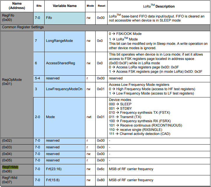
The next step was to read an array of bytes, using spiDevice.TransferFullDuplex. The SX127X transmit/receive frequency is specified in registers 0x06 RegFrMSB, 0x07 RegFrMid, and 0x08 RegFrLsb. The default frequency is 868MHz which is 0xE4, 0xC0, 0x00

static void TransferFullDuplexBufferBytesRead()
{ 
	const byte length = 3;
	byte[] writeBuffer = new byte[length + 1];
	byte[] readBuffer = new byte[length + 1];

	// Read the frequency which is 3 bytes RegFrMsb 0x6c, RegFrMid 0x80, RegFrLsb 0x00
	writeBuffer[0] = 0x06; //

	// Works, have to point at unused CS0/CS1, others could be a problem is another another SPI device is on on CS0/CS1
	//var settings = new SpiConnectionSettings(0)
	var settings = new SpiConnectionSettings(0, 0) 
	//var settings = new SpiConnectionSettings(0, 1) 
	{
		ClockFrequency = 5000000,
		Mode = SpiMode.Mode0,   // From SemTech docs pg 80 CPOL=0, CPHA=0
	};

	SpiDevice spiDevice = SpiDevice.Create(settings);

	spiDevice.TransferFullDuplex(writeBuffer, readBuffer);

	Console.WriteLine($"Register 0x06-0x{readBuffer[1]:x2} 0x07-0x{readBuffer[2]:x2} 0x08-0x{readBuffer[3]:x2}");
}
-------------------------------------------------------------------
You may only use the Microsoft .NET Core Debugger (vsdbg) with
Visual Studio Code, Visual Studio or Visual Studio for Mac software
to help you develop and test your applications.
-------------------------------------------------------------------
Loaded '/usr/lib/dotnet/shared/Microsoft.NETCore.App/5.0.4/System.Private.CoreLib.dll'. Skipped loading symbols. Module is optimized and the debugger option 'Just My Code' is enabled.
...
Loaded '/usr/lib/dotnet/shared/Microsoft.NETCore.App/5.0.4/Microsoft.Win32.Primitives.dll'. Skipped loading symbols. Module is optimized and the debugger option 'Just My Code' is enabled.
Register 0x06-0xe4 0x07-0xc0 0x08-0x00

The final step was write an array of bytes, using spiDevice.TransferFullDuplex to change the transmit/receive frequency to 915MHz. To write a value the first bit of the address byte must be set to 1 hence the 0x86 RegFrMsb address.

static void TransferFullDuplexBufferBytesWrite()
{
	const byte length = 3;
	byte[] writeBuffer = new byte[length + 1];
	byte[] readBuffer = new byte[length + 1];

	// Write the frequency which is 3 bytes RegFrMsb 0x6c, RegFrMid 0x80, RegFrLsb or with 0x00 the write mask
	writeBuffer[0] = 0x86 ;

	// Works, have to point at unused CS0/CS1, others could be a problem is another another SPI device is on on CS0/CS1
	//var settings = new SpiConnectionSettings(0)
	var settings = new SpiConnectionSettings(0, 0)
	//var settings = new SpiConnectionSettings(0, 1) 
	{
		ClockFrequency = 5000000,
		Mode = SpiMode.Mode0,   // From SemTech docs pg 80 CPOL=0, CPHA=0
	};

	SpiDevice spiDevice = SpiDevice.Create(settings);

	// Set the frequency to 915MHz
	writeBuffer[1] = 0xE4;
	writeBuffer[2] = 0xC0;
	writeBuffer[3] = 0x00;

	spiDevice.TransferFullDuplex(writeBuffer, readBuffer);
}

-------------------------------------------------------------------
You may only use the Microsoft .NET Core Debugger (vsdbg) with
Visual Studio Code, Visual Studio or Visual Studio for Mac software
to help you develop and test your applications.
-------------------------------------------------------------------
Loaded '/usr/lib/dotnet/shared/Microsoft.NETCore.App/5.0.4/System.Private.CoreLib.dll'. Skipped loading symbols. Module is optimized and the debugger option 'Just My Code' is enabled.
...
Loaded '/usr/lib/dotnet/shared/Microsoft.NETCore.App/5.0.4/Microsoft.Win32.Primitives.dll'. Skipped loading symbols. Module is optimized and the debugger option 'Just My Code' is enabled.
Register 0x06-0x6c 0x07-0x80 0x08-0x00
Register 0x06-0xe4 0x07-0xc0 0x08-0x00
The program 'dotnet' has exited with code 0 (0x0).

Summary

This exceptionally long post was to highlight that with SPI it’s all about timing, first read the datasheet, then build code to validate your understanding.

SX127X SPI interface timing diagram

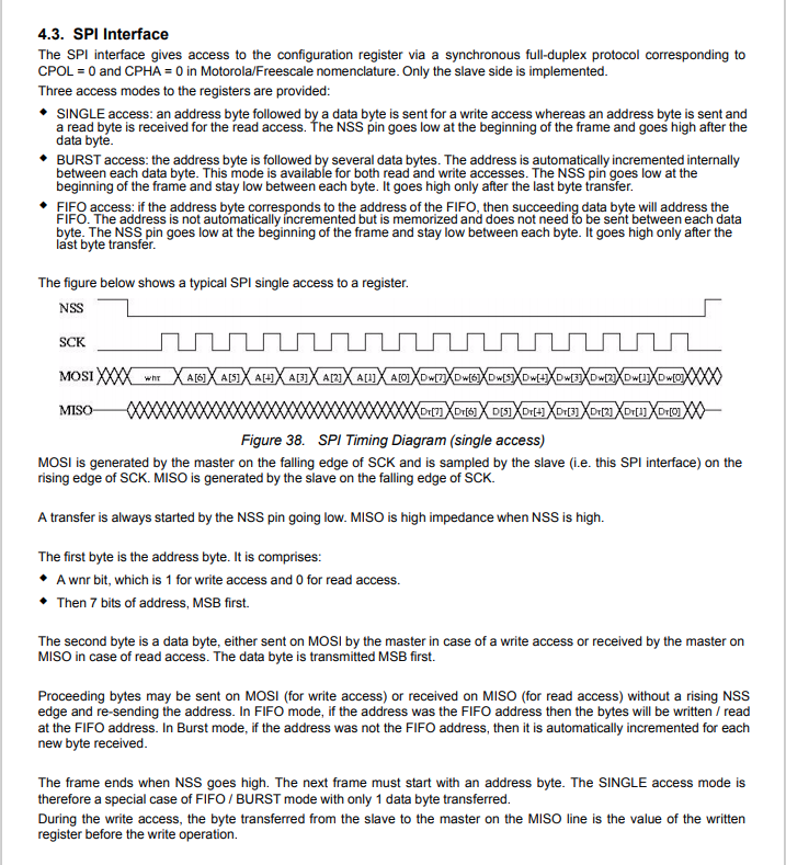
Some platforms have native TransferSequential implementations but the dotNet/IoT library only has TransferFullDuplex. SPI hardware is always full duplex, if “sequential” is available the implementation will write the provided bytes and then follow them with zeros to read the requested bytes.

.NET Core 5 Raspberry PI GPIO Interrupts

To port my Windows 10 IoT Core nRF24L01, SX123X. and SX127X LoRa libraries to .Net Core 5 I wanted to see if there were any differences in the way interrupts were handled by the dotnet/iot libraries. The initial versions of the code will being running on a Raspberry PI but I will also look at other supported Single Board Computers(SBCs).

My test-rig was a RaspberryPI 3B with a Grove Base Hat for Raspberry PI (left over from a proof of concept project), a couple of Grove Universal 4 pin 5CM cables, a Grove LED pack, and a Grove Button.

Raspberry PI test rig with Grove Base pHat, button & LED

There were some syntax differences but nothing to major

using System;
using System.Device.Gpio;
using System.Diagnostics;
using System.Threading;

namespace devMobile.NetCore.GPIOInterrupts
{
	class Program
	{
		private const int ButtonPinNumber = 5;
		private const int LedPinNumber = 16;
		private static GpioController gpiocontroller;

		static void Main(string[] args)
		{
			try
			{
				gpiocontroller = new GpioController(PinNumberingScheme.Logical);

				gpiocontroller.OpenPin(ButtonPinNumber, PinMode.InputPullDown);
				gpiocontroller.OpenPin(LedPinNumber, PinMode.Output);

				gpiocontroller.RegisterCallbackForPinValueChangedEvent(ButtonPinNumber, PinEventTypes.Rising, PinChangeEventHandler);

				Console.WriteLine($"Main thread:{Thread.CurrentThread.ManagedThreadId}");

				while (true)
				{
					Console.WriteLine($"Doing stuff");
					Thread.Sleep(1000);
				}
			}
			catch (Exception ex)
			{
				Console.WriteLine(ex.Message);
			}
		}

		private static void PinChangeEventHandler(object sender, PinValueChangedEventArgs pinValueChangedEventArgs)
		{
			Debug.Write($"Interrupt Thread:{Thread.CurrentThread.ManagedThreadId}");

			if (pinValueChangedEventArgs.ChangeType == PinEventTypes.Rising)
			{
				if (gpiocontroller.Read(LedPinNumber) == PinValue.Low)
				{
					gpiocontroller.Write(LedPinNumber, PinValue.High);
				}
				else
				{
					gpiocontroller.Write(LedPinNumber, PinValue.Low);
				}
			}
		}
	}
}

I included code to display the Thread.CurrentThread.ManagedThreadId to see if the callback was running on a different thread.

-------------------------------------------------------------------
You may only use the Microsoft .NET Core Debugger (vsdbg) with
Visual Studio Code, Visual Studio or Visual Studio for Mac software
to help you develop and test your applications.
-------------------------------------------------------------------
...
Loaded '/usr/lib/dotnet/shared/Microsoft.NETCore.App/5.0.4/Microsoft.Win32.Primitives.dll'. Skipped loading symbols. Module is optimized and the debugger option 'Just My Code' is enabled.
Main thread:1
Doing stuff
Doing stuff
Doing stuff
Doing stuff
Doing stuff
Interrupt Thread:6Doing stuff
Doing stuff
Doing stuff
Interrupt Thread:6Doing stuff
Doing stuff
Interrupt Thread:6Doing stuff
Doing stuff
Doing stuff
Doing stuff
Doing stuff
Doing stuff
The program 'dotnet' has exited with code 0 (0x0).

The ManagedThreadId for the main loop(1) was different to the callback(6) which needs some further investigation.

.NET Core 5 Raspberry PI GPIO

Next to my desk I have a stack of Raspberry PI’s and with the release of .Net Core 5 for Windows, Macintosh and Linux I decided to have another look at porting some of my nRF24L01, LoRa, and LoRaWAN libraries to .Net Core.

There are blog posts (like Deploying and Debugging Raspberry Pi .NET Applications using VS Code) about installing .Net core on a Raspberry PI, using Visual Studio Code to write an application, then deploying and debugging it over SSH which were interesting but there were a lot of steps so the likelihood me screwing up was high.

I have been using Visual Studio for C# and VB.Net code since .Net was first released (I wrote my first C# applications with Visual Studio 6) so when I stumbled across RaspberryDebugger it was time to unbox a Raspberry PI 3B and see what happened.

All coding demos start with Hello world

using System;
using System.Diagnostics;
using System.Threading;

namespace devMobile.NetCore.ConsoleApp
{
	class Program
	{
		static void Main(string[] args)
		{
			while (true)
			{
				Console.WriteLine($"{DateTime.UtcNow:HH:mm:ss} Hello World!");

				Thread.Sleep(1000);
			}
		}
	}
}

The RaspberryDebugger is really simple to install, and “frictionless” to use. The developers have put a lot of effort into making it easy to deploy and debug a .Net Core application running on a Raspberry PI with Visual Studio. All I had to do was search for, then download and install their Visual Studio Extension(VSIX).

Visual Studio Manage Extensions search

Then configure the connection information for the devices I wanted to use.

Visual Studio Options menu for RaspberryDebugger

On my main development system I was using multiple Raspberry PI devices so it was great to be able to pre-configure several devices.

RaspberryDebugger device(s) configuration)

I had connected to each device with PuTTY to check that connectivity was sorted.

RaspberryDebugger devices configuration device configuration

After typing in my “Hello world” application I had to select the device I wanted to use

Project menu RaspberryDebugger option
RaspberryDebugger device selection

Then I pressed F5 and it worked! It’s very unusual for things to work first time so I was stunned. The application was “automagically” downloaded and run in the debugger on the device.

-------------------------------------------------------------------
You may only use the Microsoft .NET Core Debugger (vsdbg) with
Visual Studio Code, Visual Studio or Visual Studio for Mac software
to help you develop and test your applications.
-------------------------------------------------------------------
Loaded '/usr/lib/dotnet/shared/Microsoft.NETCore.App/5.0.4/System.Private.CoreLib.dll'. Skipped loading symbols. Module is optimized and the debugger option 'Just My Code' is enabled.
Loaded '/home/pi/vsdbg/ConsoleApp/ConsoleApp.dll'. Symbols loaded.
Loaded '/usr/lib/dotnet/shared/Microsoft.NETCore.App/5.0.4/System.Runtime.dll'. Skipped loading symbols. Module is optimized and the debugger option 'Just My Code' is enabled.
Loaded '/usr/lib/dotnet/shared/Microsoft.NETCore.App/5.0.4/System.Console.dll'. Skipped loading symbols. Module is optimized and the debugger option 'Just My Code' is enabled.
Loaded '/usr/lib/dotnet/shared/Microsoft.NETCore.App/5.0.4/System.Threading.Thread.dll'. Skipped loading symbols. Module is optimized and the debugger option 'Just My Code' is enabled.
Loaded '/usr/lib/dotnet/shared/Microsoft.NETCore.App/5.0.4/System.Threading.dll'. Skipped loading symbols. Module is optimized and the debugger option 'Just My Code' is enabled.
Loaded '/usr/lib/dotnet/shared/Microsoft.NETCore.App/5.0.4/System.Text.Encoding.Extensions.dll'. Skipped loading symbols. Module is optimized and the debugger option 'Just My Code' is enabled.
Loaded '/usr/lib/dotnet/shared/Microsoft.NETCore.App/5.0.4/Microsoft.Win32.Primitives.dll'. Skipped loading symbols. Module is optimized and the debugger option 'Just My Code' is enabled.
05:50:37 Hello World!
05:50:39 Hello World!
05:50:40 Hello World!
05:50:41 Hello World!
05:50:42 Hello World!
05:50:43 Hello World!
...

Once the basics were sorted I wanted to check out the General Purpose Input & Output(GPIO) support implemented in the dotnet/iot libraries. My test-rig was a RaspberryPI 3B with a Grove Base Hat for Raspberry PI (left over from a Windows 10 IoT Core proof of concept project), a couple of Grove Universal 4 pin 5CM cables, a Grove LED pack, and a Grove Button.

Raspberry PI test rig with Grove Base pHat, button & LED
using System;
using System.Device.Gpio;
using System.Diagnostics;
using System.Threading;

namespace devMobile.NetCore.ConsoleGPIO1
{
	class Program
	{
		const int ButtonPinNumber = 5;
		const int LedPinNumber = 16;

		static void Main(string[] args)
		{
			try
			{
				GpioController controller = new GpioController(PinNumberingScheme.Logical);

				controller.OpenPin(ButtonPinNumber, PinMode.InputPullUp);
				controller.OpenPin(LedPinNumber, PinMode.Output);

				while (true)
				{
					if (controller.Read(ButtonPinNumber) == PinValue.High)
					{
						if (controller.Read(LedPinNumber) == PinValue.Low)
						{
							controller.Write(LedPinNumber, PinValue.High);
						}
						else
						{
							controller.Write(LedPinNumber, PinValue.Low);
						}
					}
					Thread.Sleep(100);
				}
			}
			catch (Exception ex)
			{
				Console.WriteLine(ex.Message);
			}
		}
	}
}

After starting the application, when I pressed the button the Grove LED flashed with a 100mSec duty cycle.

The RaspberryDebugger extension is a joy to use and I’m going to figure out how I can donate some money to the developers.

Windows 10 IoT Core Cognitive Services Azure IoT Hub Client

This application builds on Windows 10 IoT Core Cognitive Services Vision API client. It uses my Lego brick classifier model and a new m&m object detection model.

m&m counter test rig

I created a new Visual Studio 2017 Windows IoT Core project and copied across the Windows 10 IoT Core Cognitive Services Custom Vision API code, (changing the namespace and manifest details) and added the Azure Devices Client NuGet package.

Azure Devices Client NuGet

In the start up code I added code to initialise the Azure IoT Hub client, retrieve the device twin settings, and update the device twin properties.

try
{
	this.azureIoTHubClient = DeviceClient.CreateFromConnectionString(this.azureIoTHubConnectionString, this.transportType);
}
catch (Exception ex)
{
	this.logging.LogMessage("AzureIOT Hub DeviceClient.CreateFromConnectionString failed " + ex.Message, LoggingLevel.Error);
	return;
}

try
{
	TwinCollection reportedProperties = new TwinCollection();

	// This is from the OS
	reportedProperties["Timezone"] = TimeZoneSettings.CurrentTimeZoneDisplayName;
	reportedProperties["OSVersion"] = Environment.OSVersion.VersionString;
	reportedProperties["MachineName"] = Environment.MachineName;

	reportedProperties["ApplicationDisplayName"] = package.DisplayName;
	reportedProperties["ApplicationName"] = packageId.Name;
	reportedProperties["ApplicationVersion"] = string.Format($"{version.Major}.{version.Minor}.{version.Build}.{version.Revision}");

	// Unique identifier from the hardware
	SystemIdentificationInfo systemIdentificationInfo = SystemIdentification.GetSystemIdForPublisher();
	using (DataReader reader = DataReader.FromBuffer(systemIdentificationInfo.Id))
	{
		byte[] bytes = new byte[systemIdentificationInfo.Id.Length];
		reader.ReadBytes(bytes);
		reportedProperties["SystemId"] = BitConverter.ToString(bytes);
	}
	this.azureIoTHubClient.UpdateReportedPropertiesAsync(reportedProperties).Wait();
}
catch (Exception ex)
{
	this.logging.LogMessage("Azure IoT Hub client UpdateReportedPropertiesAsync failed " + ex.Message, LoggingLevel.Error);
	return;
}

try
{
	LoggingFields configurationInformation = new LoggingFields();

	Twin deviceTwin = this.azureIoTHubClient.GetTwinAsync().GetAwaiter().GetResult();

	if (!deviceTwin.Properties.Desired.Contains("ImageUpdateDue") || !TimeSpan.TryParse(deviceTwin.Properties.Desired["ImageUpdateDue"].value.ToString(), out imageUpdateDue))
	{
		this.logging.LogMessage("DeviceTwin.Properties ImageUpdateDue setting missing or invalid format", LoggingLevel.Warning);
		return;
	}
	configurationInformation.AddTimeSpan("ImageUpdateDue", imageUpdateDue);

	if (!deviceTwin.Properties.Desired.Contains("ImageUpdatePeriod") || !TimeSpan.TryParse(deviceTwin.Properties.Desired["ImageUpdatePeriod"].value.ToString(), out imageUpdatePeriod))
	{
		this.logging.LogMessage("DeviceTwin.Properties ImageUpdatePeriod setting missing or invalid format", LoggingLevel.Warning);
		return;
	}
…
	if (!deviceTwin.Properties.Desired.Contains("DebounceTimeout") || !TimeSpan.TryParse(deviceTwin.Properties.Desired["DebounceTimeout"].value.ToString(), out debounceTimeout))
	{
		this.logging.LogMessage("DeviceTwin.Properties DebounceTimeout setting missing or invalid format", LoggingLevel.Warning);
		return;
	}
				configurationInformation.AddTimeSpan("DebounceTimeout", debounceTimeout);

	this.logging.LogEvent("Configuration settings", configurationInformation);
}
catch (Exception ex)
{
	this.logging.LogMessage("Azure IoT Hub client GetTwinAsync failed or property missing/invalid" + ex.Message, LoggingLevel.Error);
	return;
}

When the digital input (configured in the app.settings file) is strobed or the timer fires (configured in the device properties) an image is captured, uploaded to Azure Cognitive Services Custom Vision for processing.

The returned results are then post processed to make them Azure IoT Central friendly, and finally uploaded to an Azure IoT Hub.

For testing I have used a simple object detection model.

I trained the model with images of 6 different colours of m&m’s.

For my first dataset I tagged the location of a single m&m of each of the colour in 15 images.

Testing the training of the model

I then trained the model multiple times adding additional images where the model was having trouble distiguishing colours.

The published name comes from the training performance tab

Project settings

The projectID, AzureCognitiveServicesSubscriptionKey (PredictionKey) and PublishedName (From the Performance tab in project) are from the custom vision project properties.

All of the Custom Vision model settings are configured in the Azure IoT Hub device properties.

The app.settings file contains only the hardware configuration settings and the Azure IoT Hub connection string.

{
  "InterruptPinNumber": 24,
  "interruptTriggerOn": "RisingEdge",
  "DisplayPinNumber": 35,
  "AzureIoTHubConnectionString": "",
  "TransportType": "Mqtt"
} 

The LED connected to the display pin is illuminated while an image is being processed or briefly flashed if the insufficient time between image captures has passed.

The image data is post processed differently based on the model.

// Post process the predictions based on the type of model
switch (modelType)
{
	case ModelType.Classification:
		// Use only the tags above the specified minimum probability
		foreach (var prediction in imagePrediction.Predictions)
		{
			if (prediction.Probability >= probabilityThreshold)
			{
				// Display and log the individual tag probabilities
				Debug.WriteLine($" Tag valid:{prediction.TagName} {prediction.Probability:0.00}");
				imageInformation.AddDouble($"Tag valid:{prediction.TagName}", prediction.Probability);
					telemetryDataPoint.Add(prediction.TagName, prediction.Probability);
			}
		}
		break;

	case ModelType.Detection:
		// Group the tags to get the count, include only the predictions above the specified minimum probability
		var groupedPredictions = from prediction in imagePrediction.Predictions
										 where prediction.Probability >= probabilityThreshold
										 group prediction by new { prediction.TagName }
				into newGroup
										 select new
										 {
											 TagName = newGroup.Key.TagName,
											 Count = newGroup.Count(),
										 };

		// Display and log the agregated predictions
		foreach (var prediction in groupedPredictions)
		{
			Debug.WriteLine($" Tag valid:{prediction.TagName} {prediction.Count}");
			imageInformation.AddInt32($"Tag valid:{prediction.TagName}", prediction.Count);
			telemetryDataPoint.Add(prediction.TagName, prediction.Count);
		}
		break;
	default:
		throw new ArgumentException("ModelType Invalid");
}

For a classifier only the tags with a probability greater than or equal the specified threshold are uploaded.

For a detection model the instances of each tag are counted. Only the tags with a prediction value greater than the specified threshold are included in the count.

19-08-14 05:26:14 Timer triggered
Prediction count 33
 Tag:Blue 0.0146500813
 Tag:Blue 0.61186564
 Tag:Blue 0.0923164859
 Tag:Blue 0.7813785
 Tag:Brown 0.0100603029
 Tag:Brown 0.128318727
 Tag:Brown 0.0135991769
 Tag:Brown 0.687322736
 Tag:Brown 0.846672833
 Tag:Brown 0.1826635
 Tag:Brown 0.0183384717
 Tag:Green 0.0200069249
 Tag:Green 0.367765248
 Tag:Green 0.011428359
 Tag:Orange 0.678825438
 Tag:Orange 0.03718319
 Tag:Orange 0.8643157
 Tag:Orange 0.0296728313
 Tag:Red 0.02141669
 Tag:Red 0.7183208
 Tag:Red 0.0183610674
 Tag:Red 0.0130951973
 Tag:Red 0.82097
 Tag:Red 0.0618815944
 Tag:Red 0.0130757084
 Tag:Yellow 0.04150853
 Tag:Yellow 0.0106579047
 Tag:Yellow 0.0210028365
 Tag:Yellow 0.03392527
 Tag:Yellow 0.129197285
 Tag:Yellow 0.8089519
 Tag:Yellow 0.03723789
 Tag:Yellow 0.74729687
 Tag valid:Blue 2
 Tag valid:Brown 2
 Tag valid:Orange 2
 Tag valid:Red 2
 Tag valid:Yellow 2
 05:26:17 AzureIoTHubClient SendEventAsync start
 05:26:18 AzureIoTHubClient SendEventAsync finish

The debugging output of the application includes the different categories identified in the captured image.

I found my small model was pretty good at detection of individual m&m as long as the ambient lighting was consistent, and the background fairly plain.

Sample image from test rig

Every so often the camera contrast setting went bad and could only be restored by restarting the device which needs further investigation.

Image with contrast problem

This application could be the basis for projects which need to run an Azure Cognitive Services model to count or classify then upload the results to an Azure IoT Hub or Azure IoT Central for presentation.

With a suitable model this application could be used to count the number of people in a room, which could be displayed along with the ambient temperature, humidity, CO2, and noise levels in Azure IoT Central.

The code for this application is available In on GitHub.

Windows 10 IoT Core Cognitive Services Custom Vision API

This application was inspired by one of teachers I work with wanting to count ducks in the stream on the school grounds. The school was having problems with water quality and the they wanted to see if the number of ducks was a factor. (Manually counting the ducks several times a day would be impractical).

I didn’t have a source of training images so built an image classifier using my son’s Lego for testing. In a future post I will build an object detection model once I have some sample images of the stream captured by my Windows 10 IoT Core time lapse camera application.

To start with I added the Azure Cognitive Services Custom Vision API NuGet packages to a new Visual Studio 2017 Windows IoT Core project.

Azure Custom Vision Service NuGet packacges

Then I initialised the Computer Vision API client

try
{
	this.customVisionClient = new CustomVisionPredictionClient(new System.Net.Http.DelegatingHandler[] { })
	{
		ApiKey = this.azureCognitiveServicesSubscriptionKey,
		Endpoint = this.azureCognitiveServicesEndpoint,
	};
}
catch (Exception ex)
{
	this.logging.LogMessage("Azure Cognitive Services Custom Vision Client configuration failed " + ex.Message, LoggingLevel.Error);
	return;
}

Every time the digital input is strobed by the infra red proximity sensor or touch button an image is captured, uploaded for processing, and results displayed in the debug output.

For testing I have used a simple multiclass classifier that I trained with a selection of my son’s Lego. I tagged the brick size height x width x length (1x2x3, smallest of width/height first) and colour (red, green, blue etc.)

Azure Cognitive Services Classifier project creation
Custom vision projects
Lego classifier project properties

The projectID, AzureCognitiveServicesSubscriptionKey (PredictionKey) and PublishedName (From the Performance tab in project) in the app.settings file come from the custom vision project properties.

{
  "InterruptPinNumber": 24,
  "interruptTriggerOn": "RisingEdge",
  "DisplayPinNumber": 35,
  "AzureCognitiveServicesEndpoint": "https://australiaeast.api.cognitive.microsoft.com",
  "AzureCognitiveServicesSubscriptionKey": "41234567890123456789012345678901s,
  "DebounceTimeout": "00:00:30",
  "PublishedName": "LegoBrickClassifierV3",
  "TriggerTag": "1x2x4",
  "TriggerThreshold": "0.4",
  "ProjectID": "c1234567-abcdefghijklmn-1234567890ab"
} 

The sample application only supports one trigger tag + probability and if this condition satisfied the Light Emitting Diode (LED) is turned on for 5 seconds. If an image is being processed or the minimum period between images has not passed the LED is illuminated for 5 milliseconds .

private async void InterruptGpioPin_ValueChanged(GpioPin sender, GpioPinValueChangedEventArgs args)
{
	DateTime currentTime = DateTime.UtcNow;
	Debug.WriteLine($"Digital Input Interrupt {sender.PinNumber} triggered {args.Edge}");

	if (args.Edge != this.interruptTriggerOn)
	{
		return;
	}

	// Check that enough time has passed for picture to be taken
	if ((currentTime - this.imageLastCapturedAtUtc) < this.debounceTimeout)
	{
		this.displayGpioPin.Write(GpioPinValue.High);
		this.displayOffTimer.Change(this.timerPeriodDetectIlluminated, this.timerPeriodInfinite);
		return;
	}

	this.imageLastCapturedAtUtc = currentTime;

	// Just incase - stop code being called while photo already in progress
	if (this.cameraBusy)
	{
		this.displayGpioPin.Write(GpioPinValue.High);
		this.displayOffTimer.Change(this.timerPeriodDetectIlluminated, this.timerPeriodInfinite);
		return;
	}

	this.cameraBusy = true;

	try
	{
		using (Windows.Storage.Streams.InMemoryRandomAccessStream captureStream = new Windows.Storage.Streams.InMemoryRandomAccessStream())
		{
			this.mediaCapture.CapturePhotoToStreamAsync(ImageEncodingProperties.CreateJpeg(), captureStream).AsTask().Wait();
			captureStream.FlushAsync().AsTask().Wait();
			captureStream.Seek(0);

			IStorageFile photoFile = await KnownFolders.PicturesLibrary.CreateFileAsync(ImageFilename, CreationCollisionOption.ReplaceExisting);
			ImageEncodingProperties imageProperties = ImageEncodingProperties.CreateJpeg();
			await this.mediaCapture.CapturePhotoToStorageFileAsync(imageProperties, photoFile);

			ImageAnalysis imageAnalysis = await this.computerVisionClient.AnalyzeImageInStreamAsync(captureStream.AsStreamForRead());

			Debug.WriteLine($"Tag count {imageAnalysis.Categories.Count}");

			if (imageAnalysis.Categories.Intersect(this.categoryList, new CategoryComparer()).Any())
			{
				this.displayGpioPin.Write(GpioPinValue.High);

				// Start the timer to turn the LED off
				this.displayOffTimer.Change(this.timerPeriodFaceIlluminated, this.timerPeriodInfinite);
					}

					LoggingFields imageInformation = new LoggingFields();

					imageInformation.AddDateTime("TakenAtUTC", currentTime);
					imageInformation.AddInt32("Pin", sender.PinNumber);
					Debug.WriteLine($"Categories:{imageAnalysis.Categories.Count}");
					imageInformation.AddInt32("Categories", imageAnalysis.Categories.Count);
					foreach (Category category in imageAnalysis.Categories)
					{
						Debug.WriteLine($" Category:{category.Name} {category.Score}");
						imageInformation.AddDouble($"Category:{category.Name}", category.Score);
					}

					this.logging.LogEvent("Captured image processed by Cognitive Services", imageInformation);
				}
			}
			catch (Exception ex)
			{
				this.logging.LogMessage("Camera photo or save failed " + ex.Message, LoggingLevel.Error);
			}
			finally
			{
				this.cameraBusy = false;
			}
		}

		private void TimerCallback(object state)
		{
			this.displayGpioPin.Write(GpioPinValue.Low);
		}

		internal class CategoryComparer : IEqualityComparer<Category>
		{
			public bool Equals(Category x, Category y)
			{
				if (string.Equals(x.Name, y.Name, StringComparison.OrdinalIgnoreCase))
				{
					return true;
				}

				return false;
			}

			public int GetHashCode(Category obj)
			{
				return obj.Name.GetHashCode();
			}
		}

I found my small model was pretty good at tagging images of Lego bricks as long as the ambient lighting was consistent and the background fairly plain.

When tagging many bricks my ability to distinguish pearl light grey, light grey, sand blue and grey bricks was a problem. I should have started with a limited palette (red, green, blue) of colours and shapes for my models while evaluating different tagging approaches.

The debugging output of the application includes the different categories identified in the captured image.

Digital Input Interrupt 24 triggered RisingEdge
Digital Input Interrupt 24 triggered FallingEdge
Prediction count 54
 Tag:Lime 0.529844046
 Tag:1x1x2 0.4441353
 Tag:Green 0.252290249
 Tag:1x1x3 0.1790101
 Tag:1x2x3 0.132092983
 Tag:Turquoise 0.128928885
 Tag:DarkGreen 0.09383947
 Tag:DarkTurquoise 0.08993266
 Tag:1x2x2 0.08145093
 Tag:1x2x4 0.060960535
 Tag:LightBlue 0.0525473
 Tag:MediumAzure 0.04958712
 Tag:Violet 0.04894981
 Tag:SandGreen 0.048463434
 Tag:LightOrange 0.044860106
 Tag:1X1X1 0.0426577441
 Tag:Azure 0.0416654423
 Tag:Aqua 0.0400410332
 Tag:OliveGreen 0.0387720577
 Tag:Blue 0.035169173
 Tag:White 0.03497391
 Tag:Pink 0.0321456343
 Tag:Transparent 0.0246597622
 Tag:MediumBlue 0.0245670844
 Tag:BrightPink 0.0223842952
 Tag:Flesh 0.0221406389
 Tag:Magenta 0.0208457354
 Tag:Purple 0.0188888311
 Tag:DarkPurple 0.0187285
 Tag:MaerskBlue 0.017609369
 Tag:DarkPink 0.0173041821
 Tag:Lavender 0.0162359159
 Tag:PearlLightGrey 0.0152829709
 Tag:1x1x4 0.0133710662
 Tag:Red 0.0122602312
 Tag:Yellow 0.0118704
 Tag:Clear 0.0114340987
 Tag:LightYellow 0.009903331
 Tag:Black 0.00877647
 Tag:BrightLightYellow 0.00871937349
 Tag:Mediumorange 0.0078356415
 Tag:Tan 0.00738664949
 Tag:Sand 0.00713921571
 Tag:Grey 0.00710422
 Tag:Orange 0.00624707434
 Tag:SandBlue 0.006215865
 Tag:DarkGrey 0.00613187673
 Tag:DarkBlue 0.00578308525
 Tag:DarkOrange 0.003790971
 Tag:DarkTan 0.00348462746
 Tag:LightGrey 0.00321317
 Tag:ReddishBrown 0.00304117263
 Tag:LightBluishGrey 0.00273489812
 Tag:Brown 0.00199119

I’m going to run this application repeatedly, adding more images and retraining the model to see how it performs. Once the model is working wll I’ll try downloading it and running it on a device

Custom Vision Test Harness running on my desk

This sample could be used as a basis for projects like this cat door which stops your pet bringing in dead or wounded animals. The model could be trained with tags to indicate whether the cat is carrying a “present” for their human and locking the door if it is.

RFM69 hat library Part3

Initially I tried to used the RegisterManager code from my RFM9XIoTCore library but will have to make some modifications to cope with the different Reset pin timings for the RFM69HCW device and the Reset pin not being connected on the Seegle Systeme RaspyFRM.

When I first ran the test harness I found the 3 frequency registers (RegFrfMsb, RegFrfMid, RegFrfLsb) were not getting set as I expected.

RFM69HCW reset timing diagram

After re-reading the RFM69HCW datasheet I noticed “should be pulled low for a hundred microseconds”, whereas the RFM95 datasheet had “should be pulled high for a hundred microseconds”.

RFM9X Reset timing diagram

After updating the reset GPIO pin code I could successfully set the frequency to 868MHz and then read it back

Register dump
Register 0x00 - Value 0X00 - Bits 00000000
Register 0x01 - Value 0X04 - Bits 00000100
Register 0x02 - Value 0X00 - Bits 00000000
Register 0x03 - Value 0X1a - Bits 00011010
Register 0x04 - Value 0X0b - Bits 00001011
Register 0x05 - Value 0X00 - Bits 00000000
Register 0x06 - Value 0X52 - Bits 01010010
Register 0x07 - Value 0Xe4 - Bits 11100100
Register 0x08 - Value 0Xc0 - Bits 11000000
Register 0x09 - Value 0X00 - Bits 00000000
Register 0x0a - Value 0X41 - Bits 01000001
Register 0x0b - Value 0X40 - Bits 01000000
Register 0x0c - Value 0X02 - Bits 00000010
Register 0x0d - Value 0X92 - Bits 10010010
Register 0x0e - Value 0Xf5 - Bits 11110101
Register 0x0f - Value 0X20 - Bits 00100000
Register 0x10 - Value 0X24 - Bits 00100100
Register 0x11 - Value 0X9f - Bits 10011111
Register 0x12 - Value 0X09 - Bits 00001001
Register 0x13 - Value 0X1a - Bits 00011010
Register 0x14 - Value 0X40 - Bits 01000000
Register 0x15 - Value 0Xb0 - Bits 10110000
Register 0x16 - Value 0X7b - Bits 01111011
Register 0x17 - Value 0X9b - Bits 10011011
Register 0x18 - Value 0X08 - Bits 00001000
Register 0x19 - Value 0X86 - Bits 10000110
Register 0x1a - Value 0X8a - Bits 10001010
Register 0x1b - Value 0X40 - Bits 01000000
Register 0x1c - Value 0X80 - Bits 10000000
Register 0x1d - Value 0X06 - Bits 00000110
Register 0x1e - Value 0X10 - Bits 00010000
Register 0x1f - Value 0X00 - Bits 00000000
Register 0x20 - Value 0X00 - Bits 00000000
Register 0x21 - Value 0X00 - Bits 00000000
Register 0x22 - Value 0X00 - Bits 00000000
Register 0x23 - Value 0X02 - Bits 00000010
Register 0x24 - Value 0Xff - Bits 11111111
Register 0x25 - Value 0X00 - Bits 00000000
Register 0x26 - Value 0X05 - Bits 00000101
Register 0x27 - Value 0X80 - Bits 10000000
Register 0x28 - Value 0X00 - Bits 00000000
Register 0x29 - Value 0Xff - Bits 11111111
Register 0x2a - Value 0X00 - Bits 00000000
Register 0x2b - Value 0X00 - Bits 00000000
Register 0x2c - Value 0X00 - Bits 00000000
Register 0x2d - Value 0X03 - Bits 00000011
Register 0x2e - Value 0X98 - Bits 10011000
Register 0x2f - Value 0X00 - Bits 00000000
Register 0x30 - Value 0X00 - Bits 00000000
Register 0x31 - Value 0X00 - Bits 00000000
Register 0x32 - Value 0X00 - Bits 00000000
Register 0x33 - Value 0X00 - Bits 00000000
Register 0x34 - Value 0X00 - Bits 00000000
Register 0x35 - Value 0X00 - Bits 00000000
Register 0x36 - Value 0X00 - Bits 00000000
Register 0x37 - Value 0X10 - Bits 00010000
Register 0x38 - Value 0X40 - Bits 01000000
Register 0x39 - Value 0X00 - Bits 00000000
Register 0x3a - Value 0X00 - Bits 00000000
Register 0x3b - Value 0X00 - Bits 00000000
Register 0x3c - Value 0X0f - Bits 00001111
Register 0x3d - Value 0X02 - Bits 00000010
Read RegOpMode (read byte)
Reg OpMode 0x04
Byte Hex 0x00 0x00 0xd9 0x00
Register dump
Register 0x00 - Value 0X00 - Bits 00000000
Register 0x01 - Value 0X04 - Bits 00000100
Register 0x02 - Value 0X00 - Bits 00000000
Register 0x03 - Value 0X1a - Bits 00011010
Register 0x04 - Value 0X0b - Bits 00001011
Register 0x05 - Value 0X00 - Bits 00000000
Register 0x06 - Value 0X52 - Bits 01010010
Register 0x07 - Value 0Xd9 - Bits 11011001
Register 0x08 - Value 0X00 - Bits 00000000
Register 0x09 - Value 0X00 - Bits 00000000
Register 0x0a - Value 0X41 - Bits 01000001
Register 0x0b - Value 0X40 - Bits 01000000
Register 0x0c - Value 0X02 - Bits 00000010
Register 0x0d - Value 0X92 - Bits 10010010
Register 0x0e - Value 0Xf5 - Bits 11110101
Register 0x0f - Value 0X20 - Bits 00100000
Register 0x10 - Value 0X24 - Bits 00100100
Register 0x11 - Value 0X9f - Bits 10011111
Register 0x12 - Value 0X09 - Bits 00001001
Register 0x13 - Value 0X1a - Bits 00011010
Register 0x14 - Value 0X40 - Bits 01000000
Register 0x15 - Value 0Xb0 - Bits 10110000
Register 0x16 - Value 0X7b - Bits 01111011
Register 0x17 - Value 0X9b - Bits 10011011
Register 0x18 - Value 0X08 - Bits 00001000
Register 0x19 - Value 0X86 - Bits 10000110
Register 0x1a - Value 0X8a - Bits 10001010
Register 0x1b - Value 0X40 - Bits 01000000
Register 0x1c - Value 0X80 - Bits 10000000
Register 0x1d - Value 0X06 - Bits 00000110
Register 0x1e - Value 0X10 - Bits 00010000
Register 0x1f - Value 0X00 - Bits 00000000
Register 0x20 - Value 0X00 - Bits 00000000
Register 0x21 - Value 0X00 - Bits 00000000
Register 0x22 - Value 0X00 - Bits 00000000
Register 0x23 - Value 0X02 - Bits 00000010
Register 0x24 - Value 0Xff - Bits 11111111
Register 0x25 - Value 0X00 - Bits 00000000
Register 0x26 - Value 0X05 - Bits 00000101
Register 0x27 - Value 0X80 - Bits 10000000
Register 0x28 - Value 0X00 - Bits 00000000
Register 0x29 - Value 0Xff - Bits 11111111
Register 0x2a - Value 0X00 - Bits 00000000
Register 0x2b - Value 0X00 - Bits 00000000
Register 0x2c - Value 0X00 - Bits 00000000
Register 0x2d - Value 0X03 - Bits 00000011
Register 0x2e - Value 0X98 - Bits 10011000
Register 0x2f - Value 0X00 - Bits 00000000
Register 0x30 - Value 0X00 - Bits 00000000
Register 0x31 - Value 0X00 - Bits 00000000
Register 0x32 - Value 0X00 - Bits 00000000
Register 0x33 - Value 0X00 - Bits 00000000
Register 0x34 - Value 0X00 - Bits 00000000
Register 0x35 - Value 0X00 - Bits 00000000
Register 0x36 - Value 0X00 - Bits 00000000
Register 0x37 - Value 0X10 - Bits 00010000
Register 0x38 - Value 0X40 - Bits 01000000
Register 0x39 - Value 0X00 - Bits 00000000
Register 0x3a - Value 0X00 - Bits 00000000
Register 0x3b - Value 0X00 - Bits 00000000
Register 0x3c - Value 0X0f - Bits 00001111
Register 0x3d - Value 0X02 - Bits 00000010

The next step is to extract the SPI register access functionality into a module and configure the bare minimum of settings required to get the RFM69 to transmit.

RFM69 shield library Part2

Register Dump

Next step was to dump all registers (0x00 RegFifo thru 0x4F RegTemp2) of the RFM69HCW device.

/*
    Copyright ® 2019 May devMobile Software, All Rights Reserved

	 MIT License


	 Permission is hereby granted, free of charge, to any person obtaining a copy
	 of this software and associated documentation files (the "Software"), to deal
    in the Software without restriction, including without limitation the rights
	 to use, copy, modify, merge, publish, distribute, sublicense, and/or sell
	 copies of the Software, and to permit persons to whom the Software is
    furnished to do so, subject to the following conditions:

    The above copyright notice and this permission notice shall be included in all
	 copies or substantial portions of the Software.

    THE SOFTWARE IS PROVIDED "AS IS", WITHOUT WARRANTY OF ANY KIND, EXPRESS OR
	 IMPLIED, INCLUDING BUT NOT LIMITED TO THE WARRANTIES OF MERCHANTABILITY,
    FITNESS FOR A PARTICULAR PURPOSE AND NONINFRINGEMENT. IN NO EVENT SHALL THE
	 AUTHORS OR COPYRIGHT HOLDERS BE LIABLE FOR ANY CLAIM, DAMAGES OR OTHER
	 LIABILITY, WHETHER IN AN ACTION OF CONTRACT, TORT OR OTHERWISE, ARISING FROM,
    OUT OF OR IN CONNECTION WITH THE SOFTWARE OR THE USE OR OTHER DEALINGS IN THE
	 SOFTWARE

	 RegFiFo 0x00 thru RegPacketConfig2 0x3D

*/
namespace devMobile.IoT.Rfm69Hcw.RegisterScan
{
	using System;
	using System.Diagnostics;
	using System.Threading.Tasks;
	using Windows.ApplicationModel.Background;
	using Windows.Devices.Spi;

	public sealed class Rfm69HcwDevice
	{
		private SpiDevice rfm69Hcw;

		public Rfm69HcwDevice(int chipSelectPin)
		{
			SpiController spiController = SpiController.GetDefaultAsync().AsTask().GetAwaiter().GetResult();
			var settings = new SpiConnectionSettings(chipSelectPin)
			{
				ClockFrequency = 500000,
				Mode = SpiMode.Mode0,
			};

			rfm69Hcw = spiController.GetDevice(settings);
		}

		public Byte RegisterReadByte(byte registerAddress)
		{
			byte[] writeBuffer = new byte[] { registerAddress };
			byte[] readBuffer = new byte[1];
			Debug.Assert(rfm69Hcw != null);

			rfm69Hcw.TransferSequential(writeBuffer, readBuffer);

			return readBuffer[0];
		}
	}

	public sealed class StartupTask : IBackgroundTask
	{
		private const int ChipSelectLine = 0;
		private Rfm69HcwDevice rfm69HcwDevice = new Rfm69HcwDevice(ChipSelectLine);

		public void Run(IBackgroundTaskInstance taskInstance)
		{

			while (true)
			{
				for (byte registerIndex = 0; registerIndex <= 0x4F; registerIndex++)
				{
					byte registerValue = rfm69HcwDevice.RegisterReadByte(registerIndex);

					Debug.WriteLine("Register 0x{0:x2} - Value 0X{1:x2} - Bits {2}", registerIndex, registerValue, Convert.ToString(registerValue, 2).PadLeft(8, '0'));
				}

				Task.Delay(10000).Wait();
			}
		}
	}
}

I checked a selection of values from the Debug output and they matched the defaults in the datasheet e.g. 0x07-RegFrfMsb 0xE4, 0x08-RegFrfMid 0xC0, 0x09-RegFrfLsb 0x00, 0x2C-RegPreamble 0x0, 0x2D-RegPreamble 0x03 and 0x4E-RegTemp1 0x01.

Register 0x00 - Value 0X00 - Bits 00000000
Register 0x01 - Value 0X04 - Bits 00000100
Register 0x02 - Value 0X00 - Bits 00000000
Register 0x03 - Value 0X1a - Bits 00011010
Register 0x04 - Value 0X0b - Bits 00001011
Register 0x05 - Value 0X00 - Bits 00000000
Register 0x06 - Value 0X52 - Bits 01010010
Register 0x07 - Value 0Xe4 - Bits 11100100
Register 0x08 - Value 0Xc0 - Bits 11000000
Register 0x09 - Value 0X00 - Bits 00000000
Register 0x0a - Value 0X41 - Bits 01000001
Register 0x0b - Value 0X40 - Bits 01000000
Register 0x0c - Value 0X02 - Bits 00000010
Register 0x0d - Value 0X92 - Bits 10010010
Register 0x0e - Value 0Xf5 - Bits 11110101
Register 0x0f - Value 0X20 - Bits 00100000
Register 0x10 - Value 0X24 - Bits 00100100
Register 0x11 - Value 0X9f - Bits 10011111
Register 0x12 - Value 0X09 - Bits 00001001
Register 0x13 - Value 0X1a - Bits 00011010
Register 0x14 - Value 0X40 - Bits 01000000
Register 0x15 - Value 0Xb0 - Bits 10110000
Register 0x16 - Value 0X7b - Bits 01111011
Register 0x17 - Value 0X9b - Bits 10011011
Register 0x18 - Value 0X08 - Bits 00001000
Register 0x19 - Value 0X86 - Bits 10000110
Register 0x1a - Value 0X8a - Bits 10001010
Register 0x1b - Value 0X40 - Bits 01000000
Register 0x1c - Value 0X80 - Bits 10000000
Register 0x1d - Value 0X06 - Bits 00000110
Register 0x1e - Value 0X10 - Bits 00010000
Register 0x1f - Value 0X00 - Bits 00000000
Register 0x20 - Value 0X00 - Bits 00000000
Register 0x21 - Value 0X00 - Bits 00000000
Register 0x22 - Value 0X00 - Bits 00000000
Register 0x23 - Value 0X02 - Bits 00000010
Register 0x24 - Value 0Xff - Bits 11111111
Register 0x25 - Value 0X00 - Bits 00000000
Register 0x26 - Value 0X05 - Bits 00000101
Register 0x27 - Value 0X80 - Bits 10000000
Register 0x28 - Value 0X00 - Bits 00000000
Register 0x29 - Value 0Xff - Bits 11111111
Register 0x2a - Value 0X00 - Bits 00000000
Register 0x2b - Value 0X00 - Bits 00000000
Register 0x2c - Value 0X00 - Bits 00000000
Register 0x2d - Value 0X03 - Bits 00000011
Register 0x2e - Value 0X98 - Bits 10011000
Register 0x2f - Value 0X00 - Bits 00000000
Register 0x30 - Value 0X00 - Bits 00000000
Register 0x31 - Value 0X00 - Bits 00000000
Register 0x32 - Value 0X00 - Bits 00000000
Register 0x33 - Value 0X00 - Bits 00000000
Register 0x34 - Value 0X00 - Bits 00000000
Register 0x35 - Value 0X00 - Bits 00000000
Register 0x36 - Value 0X00 - Bits 00000000
Register 0x37 - Value 0X10 - Bits 00010000
Register 0x38 - Value 0X40 - Bits 01000000
Register 0x39 - Value 0X00 - Bits 00000000
Register 0x3a - Value 0X00 - Bits 00000000
Register 0x3b - Value 0X00 - Bits 00000000
Register 0x3c - Value 0X0f - Bits 00001111
Register 0x3d - Value 0X02 - Bits 00000010
Register 0x3e - Value 0X00 - Bits 00000000
Register 0x3f - Value 0X00 - Bits 00000000
Register 0x40 - Value 0X00 - Bits 00000000
Register 0x41 - Value 0X00 - Bits 00000000
Register 0x42 - Value 0X00 - Bits 00000000
Register 0x43 - Value 0X00 - Bits 00000000
Register 0x44 - Value 0X00 - Bits 00000000
Register 0x45 - Value 0X00 - Bits 00000000
Register 0x46 - Value 0X00 - Bits 00000000
Register 0x47 - Value 0X00 - Bits 00000000
Register 0x48 - Value 0X00 - Bits 00000000
Register 0x49 - Value 0X00 - Bits 00000000
Register 0x4a - Value 0X00 - Bits 00000000
Register 0x4b - Value 0X00 - Bits 00000000
Register 0x4c - Value 0X00 - Bits 00000000
Register 0x4d - Value 0X00 - Bits 00000000
Register 0x4e - Value 0X01 - Bits 00000001
Register 0x4f - Value 0X00 - Bits 00000000

RFM69 shield library Part1

Register Read

After building an RFM95 Windows 10 IoT Core C# library I wanted to see if I could source a couple of RFM69HCW hats and write another library. For some applications the RFM69HCW with the variety and number of low-power client devices available plus, its built in payload encryption and addressing make it a better option. For the RFM9X library I purchased several RM9X Raspberry PI Hats but I can only find a couple (May 2019) of suitable RFM69HCW ones.

  • Adafruit RFM69HCW Radio Bonnet 433/868/915MHz USD19.95
  • Seegel Systeme RaspyRFMII EUR17.90

I wanted a lightweight RFM69HCW library which didn’t try to hide how the chip functioned, and in the future could be configured to work with other vendors’ shields.

AdaFruit LoRa 9X/RFM69HCW Radio Bonnet
Seegel Systeme RaspyRFM-II

The first step was to build a basic universal windows platform (UWP) background task to confirm that I could reliably communicate with the AdaFruit shield over the SPI bus by reading a single register value (RegVersion the silicon version specified in the vendor datasheet).

/*
    Copyright ® 2019 May devMobile Software, All Rights Reserved
 
    MIT License

    Permission is hereby granted, free of charge, to any person obtaining a copy
    of this software and associated documentation files (the "Software"), to deal
    in the Software without restriction, including without limitation the rights
    to use, copy, modify, merge, publish, distribute, sublicense, and/or sell
    copies of the Software, and to permit persons to whom the Software is
    furnished to do so, subject to the following conditions:

    The above copyright notice and this permission notice shall be included in all
    copies or substantial portions of the Software.

    THE SOFTWARE IS PROVIDED "AS IS", WITHOUT WARRANTY OF ANY KIND, EXPRESS OR
    IMPLIED, INCLUDING BUT NOT LIMITED TO THE WARRANTIES OF MERCHANTABILITY,
    FITNESS FOR A PARTICULAR PURPOSE AND NONINFRINGEMENT. IN NO EVENT SHALL THE
    AUTHORS OR COPYRIGHT HOLDERS BE LIABLE FOR ANY CLAIM, DAMAGES OR OTHER
    LIABILITY, WHETHER IN AN ACTION OF CONTRACT, TORT OR OTHERWISE, ARISING FROM,
    OUT OF OR IN CONNECTION WITH THE SOFTWARE OR THE USE OR OTHER DEALINGS IN THE
    SOFTWARE

	 CS : CE1
	 RST : GPIO25
	 IRQ : GPIO22 (DIO0)
	 Unused : GPIO23 (DIO1)
	 Unused : GPIO24 (DIO2)
 */
namespace devMobile.IoT.Rfm69hcw.AdafruitSPI
{
	using System;
	using System.Diagnostics;
	using System.Threading;
	using Windows.ApplicationModel.Background;
	using Windows.Devices.Spi;

	public sealed class StartupTask : IBackgroundTask
	{
		private const byte RegVersion = 0x10;

		public void Run(IBackgroundTaskInstance taskInstance)
		{
			SpiController spiController = SpiController.GetDefaultAsync().AsTask().GetAwaiter().GetResult();
			var settings = new SpiConnectionSettings(1)
			{
				ClockFrequency = 500000,
				Mode = SpiMode.Mode0,
			};

			SpiDevice Device = spiController.GetDevice(settings);

			while (true)
			{
				byte[] writeBuffer = new byte[] { RegVersion }; // RegVersion
				byte[] readBuffer = new byte[1];

				Device.TransferSequential(writeBuffer, readBuffer);

				byte registerValue = readBuffer[0];
				Debug.WriteLine("Register 0x{0:x2} - Value 0X{1:x2} - Bits {2}", RegVersion, registerValue, Convert.ToString(registerValue, 2).PadLeft(8, '0'));

				Thread.Sleep(10000);
			}
		}
	}
}

The AdaFruit hat uses chip select 1

/*
    Copyright ® 2019 May devMobile Software, All Rights Reserved
 
    MIT License

    Permission is hereby granted, free of charge, to any person obtaining a copy
    of this software and associated documentation files (the "Software"), to deal
    in the Software without restriction, including without limitation the rights
    to use, copy, modify, merge, publish, distribute, sublicense, and/or sell
    copies of the Software, and to permit persons to whom the Software is
    furnished to do so, subject to the following conditions:

    The above copyright notice and this permission notice shall be included in all
    copies or substantial portions of the Software.

    THE SOFTWARE IS PROVIDED "AS IS", WITHOUT WARRANTY OF ANY KIND, EXPRESS OR
    IMPLIED, INCLUDING BUT NOT LIMITED TO THE WARRANTIES OF MERCHANTABILITY,
    FITNESS FOR A PARTICULAR PURPOSE AND NONINFRINGEMENT. IN NO EVENT SHALL THE
    AUTHORS OR COPYRIGHT HOLDERS BE LIABLE FOR ANY CLAIM, DAMAGES OR OTHER
    LIABILITY, WHETHER IN AN ACTION OF CONTRACT, TORT OR OTHERWISE, ARISING FROM,
    OUT OF OR IN CONNECTION WITH THE SOFTWARE OR THE USE OR OTHER DEALINGS IN THE
    SOFTWARE

    The RaspyRFM is plugged into the Raspberry PI of pin 17-26.

    From the docs for the dual RFM69 mini 
    17 -> 3,3 V
    18 (GPIO 24) -> DIO1 bei Einzelmodul, DIO0 Slave bei Doppelmodul
    19 (MOSI) -> MOSI
    20 -> GND
    21 (MISO) ->MISO
    22 (GPIO 25) -> DIO0
    23 (SCK) -> SCK
    24 (CE0) -> NSS Master
    25 -> GND
    26 (CE1) -> DIO2 bei Einzelmodul, NSS Slave bei Doppelmodul
 */
namespace devMobile.IoT.Rfm69hcw.SeegelSpi
{
	using System;
	using System.Diagnostics;
	using System.Threading;
	using Windows.ApplicationModel.Background;
	using Windows.Devices.Spi;

	public sealed class StartupTask : IBackgroundTask
	{
		private const byte RegVersion = 0x10;

		public void Run(IBackgroundTaskInstance taskInstance)
		{
			SpiController spiController = SpiController.GetDefaultAsync().AsTask().GetAwaiter().GetResult();
			var settings = new SpiConnectionSettings(0)
			{
				ClockFrequency = 500000,
				Mode = SpiMode.Mode0,
			};

			SpiDevice Device = spiController.GetDevice(settings);

			while (true)
			{
				byte[] writeBuffer = new byte[] { RegVersion }; // RegVersion
				byte[] readBuffer = new byte[1];

				Device.TransferSequential(writeBuffer, readBuffer);

				byte registerValue = readBuffer[0];
				Debug.WriteLine("Register 0x{0:x2} - Value 0X{1:x2} - Bits {2}", RegVersion, registerValue, Convert.ToString(registerValue, 2).PadLeft(8, '0'));

				Thread.Sleep(10000);
			}
		}
	}
}


The Seegel hat uses chip select 0

Based on the datasheet the RegVersion (0x10) register the value (ox24) returned by both hats was correct.

'backgroundTaskHost.exe' (CoreCLR: CoreCLR_UWP_Domain): Loaded 'C:\Data\Programs\WindowsApps\Microsoft.NET.CoreFramework.Debug.2.2_2.2.27505.2_arm__8wekyb3d8bbwe\System.Threading.Thread.dll'. Skipped loading symbols. Module is optimized and the debugger option 'Just My Code' is enabled.
Register 0x10 - Value 0X24 - Bits 00100100

Next step is to dump all the registers of the HopeRF module

Grove Base Hat for Raspberry PI Zero Windows 10 IoT Core

During the week a package arrived from Seeedstudio with a Grove Base Hat for RPI Zero. So I have modified my Grove Base Hat for RPI Windows 10 IoT Core library to add support for the new shield.

Grove Base Hat for Raspberry PI Zero on Raspberry PI 3

The Raspberry PI Zero hat has a two less analog ports and a different device id so some conditional compile options were necessary

namespace devMobile.Windows10IoTCore.GroveBaseHatRPI
{
#if (!GROVE_BASE_HAT_RPI && !GROVE_BASE_HAT_RPI_ZERO)
#error Library must have at least one of GROVE_BASE_HAT_RPI or GROVE_BASE_HAT_RPI_ZERO defined
#endif

#if (GROVE_BASE_HAT_RPI && GROVE_BASE_HAT_RPI_ZERO)
#error Library must have at most one of GROVE_BASE_HAT_RPI or GROVE_BASE_HAT_RPI_ZERO defined
#endif

	public class AnalogPorts : IDisposable
	{
		private const int I2CAddress = 0x04;
		private const byte RegisterDeviceId = 0x0;
		private const byte RegisterVersion = 0x02;
		private const byte RegisterPowerSupplyVoltage = 0x29;
		private const byte RegisterRawBase = 0x10;
		private const byte RegisterVoltageBase = 0x20;
		private const byte RegisterValueBase = 0x30;
#if GROVE_BASE_HAT_RPI
		private const byte DeviceId = 0x0004;
#endif
#if GROVE_BASE_HAT_RPI_ZERO
		private const byte DeviceId = 0x0005;
#endif
		private I2cDevice Device= null;
		private bool Disposed = false;

		public enum AnalogPort
		{
			A0 = 0,
			A1 = 1,
			A2 = 2,
			A3 = 3,
			A4 = 4,
			A5 = 5,
#if GROVE_BASE_HAT_RPI
			A6 = 6,
			A7 = 7,
#endif
		};

The code updates have been “smoke” tested and I have updated the GitHub repository.

Windows 10 IoT Core Cognitive Services Computer Vision API

This application was inspired by one of teachers I work with wanting to check occupancy of different areas in the school library. I had been using the Computer Vision service to try and identify objects around my home and office which had been moderately successful but not terribly useful or accurate.

I added the Azure Cognitive Services Computer Vision API NuGet packages to my Visual Studio 2017 Windows IoT Core project.

Azure Cognitive Services Computer Vision API library

Then I initialised the Computer Vision API client

try
{
	this.computerVisionClient = new ComputerVisionClient(
			 new Microsoft.Azure.CognitiveServices.Vision.ComputerVision.ApiKeyServiceClientCredentials(this.azureCognitiveServicesSubscriptionKey),
			 new System.Net.Http.DelegatingHandler[] { })
	{
		Endpoint = this.azureCognitiveServicesEndpoint,
	};
}
catch (Exception ex)
{
	this.logging.LogMessage("Azure Cognitive Services Computer Vision client configuration failed " + ex.Message, LoggingLevel.Error);
	return;
}

Every time the digital input is strobed by the passive infra red motion detector an image is captured, then uploaded for processing, and finally results displayed. For this sample I’m looking for categories which indicate the image is of a group of people (The categories are configured in the appsettings file)

{
  "InterruptPinNumber": 24,
  "interruptTriggerOn": "RisingEdge",
  "DisplayPinNumber": 35,
  "AzureCognitiveServicesEndpoint": "https://australiaeast.api.cognitive.microsoft.com/",
  "AzureCognitiveServicesSubscriptionKey": "1234567890abcdefghijklmnopqrstuv",
  "ComputerVisionCategoryNames":"people_group,people_many",
  "LocalImageFilenameFormatLatest": "{0}.jpg",
  "LocalImageFilenameFormatHistoric": "{1:yyMMddHHmmss}.jpg",
  "DebounceTimeout": "00:00:30"
} 

If any of the specified categories are identified in the image I illuminate a Light Emitting Diode (LED) for 5 seconds, if an image is being processed or the minimum period between images has not passed the LED is illuminated for 5 milliseconds .

		private async void InterruptGpioPin_ValueChanged(GpioPin sender, GpioPinValueChangedEventArgs args)
		{
			DateTime currentTime = DateTime.UtcNow;
			Debug.WriteLine($"Digital Input Interrupt {sender.PinNumber} triggered {args.Edge}");

			if (args.Edge != this.interruptTriggerOn)
			{
				return;
			}

			// Check that enough time has passed for picture to be taken
			if ((currentTime - this.imageLastCapturedAtUtc) < this.debounceTimeout)
			{
				this.displayGpioPin.Write(GpioPinValue.High);
				this.displayOffTimer.Change(this.timerPeriodDetectIlluminated, this.timerPeriodInfinite);
				return;
			}

			this.imageLastCapturedAtUtc = currentTime;

			// Just incase - stop code being called while photo already in progress
			if (this.cameraBusy)
			{
				this.displayGpioPin.Write(GpioPinValue.High);
				this.displayOffTimer.Change(this.timerPeriodDetectIlluminated, this.timerPeriodInfinite);
				return;
			}

			this.cameraBusy = true;

			try
			{
				using (Windows.Storage.Streams.InMemoryRandomAccessStream captureStream = new Windows.Storage.Streams.InMemoryRandomAccessStream())
				{
					this.mediaCapture.CapturePhotoToStreamAsync(ImageEncodingProperties.CreateJpeg(), captureStream).AsTask().Wait();
					captureStream.FlushAsync().AsTask().Wait();
					captureStream.Seek(0);

					IStorageFile photoFile = await KnownFolders.PicturesLibrary.CreateFileAsync(ImageFilename, CreationCollisionOption.ReplaceExisting);
					ImageEncodingProperties imageProperties = ImageEncodingProperties.CreateJpeg();
					await this.mediaCapture.CapturePhotoToStorageFileAsync(imageProperties, photoFile);

					ImageAnalysis imageAnalysis = await this.computerVisionClient.AnalyzeImageInStreamAsync(captureStream.AsStreamForRead());

					Debug.WriteLine($"Tag count {imageAnalysis.Categories.Count}");

					if (imageAnalysis.Categories.Intersect(this.categoryList, new CategoryComparer()).Any())
					{
						this.displayGpioPin.Write(GpioPinValue.High);

						// Start the timer to turn the LED off
						this.displayOffTimer.Change(this.timerPeriodFaceIlluminated, this.timerPeriodInfinite);
					}

					LoggingFields imageInformation = new LoggingFields();

					imageInformation.AddDateTime("TakenAtUTC", currentTime);
					imageInformation.AddInt32("Pin", sender.PinNumber);
					Debug.WriteLine($"Categories:{imageAnalysis.Categories.Count}");
					imageInformation.AddInt32("Categories", imageAnalysis.Categories.Count);
					foreach (Category category in imageAnalysis.Categories)
					{
						Debug.WriteLine($" Category:{category.Name} {category.Score}");
						imageInformation.AddDouble($"Category:{category.Name}", category.Score);
					}

					this.logging.LogEvent("Captured image processed by Cognitive Services", imageInformation);
				}
			}
			catch (Exception ex)
			{
				this.logging.LogMessage("Camera photo or save failed " + ex.Message, LoggingLevel.Error);
			}
			finally
			{
				this.cameraBusy = false;
			}
		}

		private void TimerCallback(object state)
		{
			this.displayGpioPin.Write(GpioPinValue.Low);
		}

		internal class CategoryComparer : IEqualityComparer<Category>
		{
			public bool Equals(Category x, Category y)
			{
				if (string.Equals(x.Name, y.Name, StringComparison.OrdinalIgnoreCase))
				{
					return true;
				}

				return false;
			}

			public int GetHashCode(Category obj)
			{
				return obj.Name.GetHashCode();
			}
		}

I found that the Computer vision service was pretty good at categorising photos of images like this displayed on my second monitor as containing a group of people.

The debugging output of the application includes the different categories identified in the captured image.

Digital Input Interrupt 24 triggered RisingEdge
Digital Input Interrupt 24 triggered FallingEdge
'backgroundTaskHost.exe' (CoreCLR: CoreCLR_UWP_Domain): Loaded 'C:\Data\Programs\WindowsApps\Microsoft.NET.CoreFramework.Debug.2.2_2.2.27505.2_arm__8wekyb3d8bbwe\System.Diagnostics.DiagnosticSource.dll'. Skipped loading symbols. Module is optimized and the debugger option 'Just My Code' is enabled.
'backgroundTaskHost.exe' (CoreCLR: CoreCLR_UWP_Domain): Loaded 'C:\Data\Programs\WindowsApps\Microsoft.NET.CoreFramework.Debug.2.2_2.2.27505.2_arm__8wekyb3d8bbwe\System.Collections.NonGeneric.dll'. Skipped loading symbols. Module is optimized and the debugger option 'Just My Code' is enabled.
'backgroundTaskHost.exe' (CoreCLR: CoreCLR_UWP_Domain): Loaded 'C:\Data\Programs\WindowsApps\Microsoft.NET.CoreFramework.Debug.2.2_2.2.27505.2_arm__8wekyb3d8bbwe\System.Runtime.Serialization.Formatters.dll'. Skipped loading symbols. Module is optimized and the debugger option 'Just My Code' is enabled.
'backgroundTaskHost.exe' (CoreCLR: CoreCLR_UWP_Domain): Loaded 'C:\Data\Programs\WindowsApps\Microsoft.NET.CoreFramework.Debug.2.2_2.2.27505.2_arm__8wekyb3d8bbwe\System.Diagnostics.TraceSource.dll'. Skipped loading symbols. Module is optimized and the debugger option 'Just My Code' is enabled.
'backgroundTaskHost.exe' (CoreCLR: CoreCLR_UWP_Domain): Loaded 'C:\Data\Programs\WindowsApps\Microsoft.NET.CoreFramework.Debug.2.2_2.2.27505.2_arm__8wekyb3d8bbwe\System.Collections.Specialized.dll'. Skipped loading symbols. Module is optimized and the debugger option 'Just My Code' is enabled.
'backgroundTaskHost.exe' (CoreCLR: CoreCLR_UWP_Domain): Loaded 'C:\Data\Programs\WindowsApps\Microsoft.NET.CoreFramework.Debug.2.2_2.2.27505.2_arm__8wekyb3d8bbwe\System.Drawing.Primitives.dll'. Skipped loading symbols. Module is optimized and the debugger option 'Just My Code' is enabled.
'backgroundTaskHost.exe' (CoreCLR: CoreCLR_UWP_Domain): Loaded 'C:\Data\Programs\WindowsApps\Microsoft.NET.CoreFramework.Debug.2.2_2.2.27505.2_arm__8wekyb3d8bbwe\System.Runtime.Serialization.Primitives.dll'. Skipped loading symbols. Module is optimized and the debugger option 'Just My Code' is enabled.
'backgroundTaskHost.exe' (CoreCLR: CoreCLR_UWP_Domain): Loaded 'C:\Data\Programs\WindowsApps\Microsoft.NET.CoreFramework.Debug.2.2_2.2.27505.2_arm__8wekyb3d8bbwe\System.Data.Common.dll'. Skipped loading symbols. Module is optimized and the debugger option 'Just My Code' is enabled.
'backgroundTaskHost.exe' (CoreCLR: CoreCLR_UWP_Domain): Loaded 'C:\Data\Programs\WindowsApps\Microsoft.NET.CoreFramework.Debug.2.2_2.2.27505.2_arm__8wekyb3d8bbwe\System.Xml.ReaderWriter.dll'. Skipped loading symbols. Module is optimized and the debugger option 'Just My Code' is enabled.
'backgroundTaskHost.exe' (CoreCLR: CoreCLR_UWP_Domain): Loaded 'C:\Data\Programs\WindowsApps\Microsoft.NET.CoreFramework.Debug.2.2_2.2.27505.2_arm__8wekyb3d8bbwe\System.Private.Xml.dll'. Skipped loading symbols. Module is optimized and the debugger option 'Just My Code' is enabled.
'backgroundTaskHost.exe' (CoreCLR: CoreCLR_UWP_Domain): Loaded 'Anonymously Hosted DynamicMethods Assembly'. 
Tag count 1
Categories:1
 Category:people_group 0.8671875
The thread 0x634 has exited with code 0 (0x0).

I used an infrared motion sensor to trigger capture and processing of an image to simulate a application for detecting if there is a group of people in an area of the school library.

I’m going to run this application alongside one of my time-lapse applications to record a days worth of images and manually check the accuracy of the image categorisation. I think that camera location maybe important as well so I’ll try a selection of different USB cameras and locations.

Trial PIR triggered computer vision client

I also found the small PIR motion detector didn’t work very well in a larger space so I’m going to trial a configurable sensor and a repurposed burglar alarm sensor.