Random wanderings through Microsoft Azure esp. PaaS plumbing, the IoT bits, AI on Micro controllers, AI on Edge Devices, .NET nanoFramework, .NET Core on *nix and ML.NET+ONNX
STM32F691Discovery with EVB plugged into Arduino headers
My Over the Air Activation(OTAA) implementation is pretty “nasty” I assumed that there would be no timeouts or failures and I only send one BCD message “48656c6c6f204c6f526157414e” which is “hello LoRaWAN”
I configured the RAK811 module for LoRaWAN
// Set the Working mode to LoRaWAN
bytesWritten = outputDataWriter.WriteString("at+set_config=lora:work_mode:0\r\n");
Debug.WriteLine($"TX: work_mode {outputDataWriter.UnstoredBufferLength} bytes to output stream.");
txByteCount = outputDataWriter.Store();
Debug.WriteLine($"TX: {txByteCount} bytes via {serialDevice.PortName}");

// Read the response
bytesRead = inputDataReader.Load(128);
if (bytesRead > 0)
{
   string response = inputDataReader.ReadString(bytesRead);
   Debug.WriteLine($"RX sync:{response}");
}
Then just sequentially stepped through the necessary configuration to join the TTN network
// Set the Region to AS923
bytesWritten = outputDataWriter.WriteString("at+set_config=lora:region:AS923\r\n");
Debug.WriteLine($"TX: region {outputDataWriter.UnstoredBufferLength} bytes to output stream.");
txByteCount = outputDataWriter.Store();
Debug.WriteLine($"TX: {txByteCount} bytes via {serialDevice.PortName}");

// Read the response
bytesRead = inputDataReader.Load(128);
if (bytesRead > 0)
{
   String response = inputDataReader.ReadString(bytesRead);
   Debug.WriteLine($"RX sync:{response}");
}

// Set the JoinMode
bytesWritten = outputDataWriter.WriteString($"at+set_config=lora:join_mode:0\r\n");
Debug.WriteLine($"TX: join_mode {outputDataWriter.UnstoredBufferLength} bytes to output stream.");
txByteCount = outputDataWriter.Store();
Debug.WriteLine($"TX: {txByteCount} bytes via {serialDevice.PortName}");

// Read the response
bytesRead = inputDataReader.Load(128);
if (bytesRead > 0)
{
   String response = inputDataReader.ReadString(bytesRead);
   Debug.WriteLine($"RX sync:{response}");
}

// OTAA set the devEUI
bytesWritten = outputDataWriter.WriteString($"at+set_config=lora:dev_eui:{devEui}\r\n");
Debug.WriteLine($"TX: dev_eui {outputDataWriter.UnstoredBufferLength} bytes to output stream.");
txByteCount = outputDataWriter.Store();
Debug.WriteLine($"TX: {txByteCount} bytes via {serialDevice.PortName}");

// Read the response
bytesRead = inputDataReader.Load(128);
if (bytesRead > 0)
{
   String response = inputDataReader.ReadString(bytesRead);
   Debug.WriteLine($"RX sync:{response}");
}
...
The code is not suitable for production but it confirmed my software and hardware configuration worked.
The thread '<No Name>' (0x2) has exited with code 0 (0x0).
devMobile.IoT.Rak811.NetworkJoinOTAA starting
COM5,COM6
TX: work_mode 32 bytes to output stream.
TX: 32 bytes via COM6
RX sync:UART1 work mode: RUI_UART_NORAMAL
Current work_mode:LoRaWAN, join_mode:OTAA, Class: A
Initialization OK

TX: region 33 bytes to output stream.
TX: 33 bytes via COM6
RX sync:OK

TX: join_mode 32 bytes to output stream.
TX: 32 bytes via COM6
RX sync:OK

TX: dev_eui 45 bytes to output stream.
TX: 45 bytes via COM6
RX sync:OK

TX: app_eui 45 bytes to output stream.
TX: 45 bytes via COM6
RX sync:OK

TX: app_key 61 bytes to output stream.
TX: 61 bytes via COM6
RX sync:OK

TX: confirm 30 bytes to output stream.
TX: 30 bytes via COM6
RX sync:OK

TX: join 9 bytes to output stream.
TX: 9 bytes via COM6
RX sync:
RX sync:
RX sync:
RX sync:
RX sync:OK Join Success

TX: send 43 bytes to output stream.
TX: 43 bytes via COM6
TX: send 43 bytes to output stream.
TX: 43 bytes via COM6
RX sync:OK
at+recv=0,-59,9,0
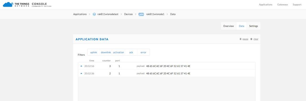
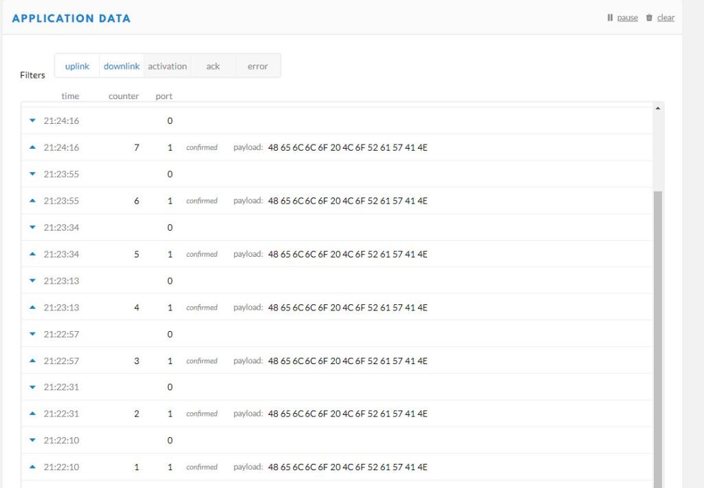
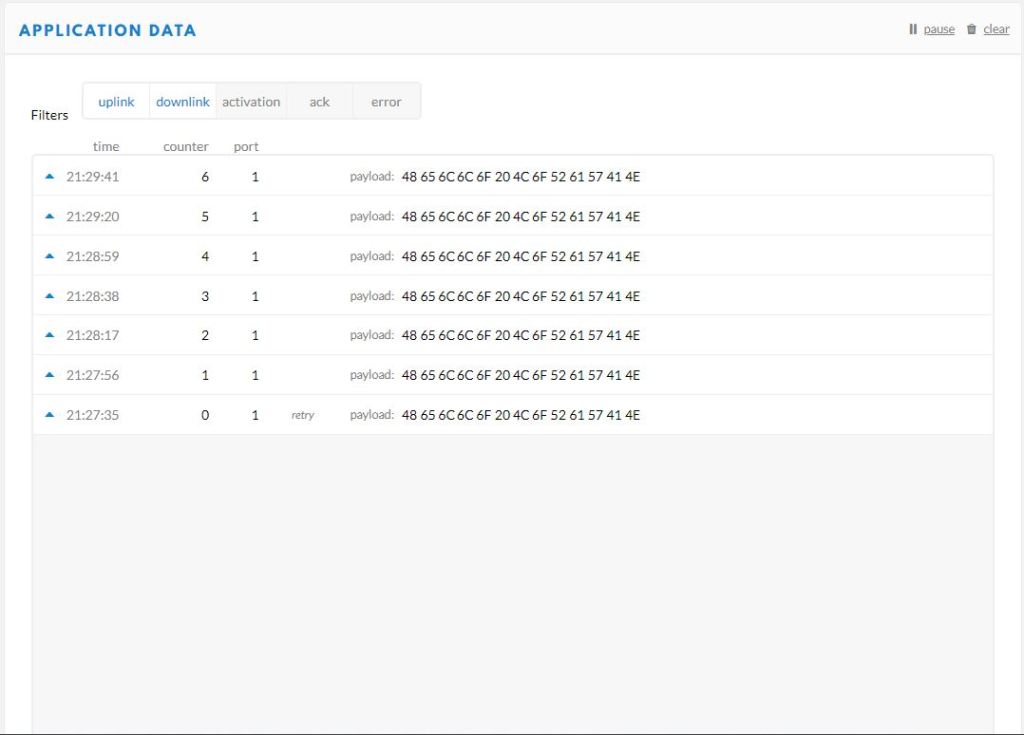
In the Visual Studio 2019 debug out put I could see messages getting sent and then after a short delay they were visible in the TTN console.
I then modified the confirmed flag and in the TTN console I could see how they were processed differently.
Confirmed messagesUnconfirmed messages
I could receive messages but as the RAK 811 module can be configured to be a Class C device there didn’t appear to be a way to receive a message without sending one which seemed a bit odd.
The next step is to get Authentication By Personalisation(ABP) working.
When writing communications libraries one of the first things I try and get working is a “factory reset”. At some stage I will misconfigure the device so badly that it won’t work anymore and having a way to return to the device to its original configuration is really useful.
//---------------------------------------------------------------------------------
// Copyright (c) June 2020, devMobile Software
//
// Licensed under the Apache License, Version 2.0 (the "License");
// you may not use this file except in compliance with the License.
// You may obtain a copy of the License at
//
//     http://www.apache.org/licenses/LICENSE-2.0
//
// Unless required by applicable law or agreed to in writing, software
// distributed under the License is distributed on an "AS IS" BASIS,
// WITHOUT WARRANTIES OR CONDITIONS OF ANY KIND, either express or implied.
// See the License for the specific language governing permissions and
// limitations under the License.
//
//---------------------------------------------------------------------------------
// nanoff --target ST_STM32F769I_DISCOVERY --update
//#define SERIAL_SYNC_READ
//#define HARDWARE_RESET
//#define SOFTWARE_RESTART
//#define DEVICE_STATUS
//#define LORA_STATUS
namespace devMobile.IoT.Rak811.FactoryReset
{
   using System;
   using System.Diagnostics;
   using System.Threading;
   using Windows.Devices.Gpio;
   using Windows.Devices.SerialCommunication;
   using Windows.Storage.Streams;

   public class Program
   {
      private const string SerialPortId = "COM6";

      public static void Main()
      {
         SerialDevice serialDevice;

         Debug.WriteLine("devMobile.IoT.Rak811.FactoryReset starting");

         Debug.WriteLine(Windows.Devices.SerialCommunication.SerialDevice.GetDeviceSelector());

         try
         {
#if HARDWARE_RESET
            GpioPin resetPin = GpioController.GetDefault().OpenPin(PinNumber('J', 4));
            resetPin.SetDriveMode(GpioPinDriveMode.Output);
            resetPin.Write(GpioPinValue.Low);
#endif
            serialDevice = SerialDevice.FromId(SerialPortId);

            // set parameters
            serialDevice.BaudRate = 9600;
            serialDevice.Parity = SerialParity.None;
            serialDevice.StopBits = SerialStopBitCount.One;
            serialDevice.Handshake = SerialHandshake.None;
            serialDevice.DataBits = 8;

            serialDevice.ReadTimeout = new TimeSpan(0, 0, 30);
            serialDevice.WriteTimeout = new TimeSpan(0, 0, 4);

            DataWriter outputDataWriter = new DataWriter(serialDevice.OutputStream);

#if SERIAL_SYNC_READ
            DataReader inputDataReader = new DataReader(serialDevice.InputStream);
#else
            serialDevice.DataReceived += SerialDevice_DataReceived;
#endif

            // set a watch char to be notified when it's available in the input stream
            serialDevice.WatchChar = '\n';

            while (true)
            {
#if HARDWARE_RESET
               resetPin.Write(GpioPinValue.High);
               Thread.Sleep(10);
               resetPin.Write(GpioPinValue.Low);
#endif

#if SOFTWARE_RESTART
               uint bytesWritten = outputDataWriter.WriteString("at+set_config=device:restart\r\n");
               Debug.WriteLine($"TX: {outputDataWriter.UnstoredBufferLength} bytes to output stream.");

               // calling the 'Store' method on the data writer actually sends the data
               uint txByteCount = outputDataWriter.Store();
               Debug.WriteLine($"TX: {txByteCount} bytes via {serialDevice.PortName}");
#endif

#if DEVICE_STATUS
               uint bytesWritten = outputDataWriter.WriteString("at+get_config=device:status\r\n");
               Debug.WriteLine($"TX: {outputDataWriter.UnstoredBufferLength} bytes to output stream.");

               // calling the 'Store' method on the data writer actually sends the data
               uint txByteCount = outputDataWriter.Store();
               Debug.WriteLine($"TX: {txByteCount} bytes via {serialDevice.PortName}");
#endif

#if LORA_STATUS
               uint bytesWritten = outputDataWriter.WriteString("at+get_config=lora:status\r\n");
               Debug.WriteLine($"TX: {outputDataWriter.UnstoredBufferLength} bytes to output stream.");

               // calling the 'Store' method on the data writer actually sends the data
               uint txByteCount = outputDataWriter.Store();
               Debug.WriteLine($"TX: {txByteCount} bytes via {serialDevice.PortName}");
#endif

#if SERIAL_SYNC_READ
               // June 2020 appears to be limited to 256 chars
               uint bytesRead = inputDataReader.Load(50);

               Debug.WriteLine($"RXs :{bytesRead} bytes read from {serialDevice.PortName}");

               if (bytesRead > 0)
               {
                  String response = inputDataReader.ReadString(bytesRead);
                  Debug.WriteLine($"RX sync:{response}");
               }
#endif

               Thread.Sleep(20000);
            }
         }
         catch (Exception ex)
         {
            Debug.WriteLine(ex.Message);
         }
      }

      private static void SerialDevice_DataReceived(object sender, SerialDataReceivedEventArgs e)
      {
         switch (e.EventType)
         {
            case SerialData.Chars:
               //Debug.WriteLine("RX SerialData.Chars");
               break;

            case SerialData.WatchChar:
               Debug.WriteLine("RX: SerialData.WatchChar");
               SerialDevice serialDevice = (SerialDevice)sender;

               using (DataReader inputDataReader = new DataReader(serialDevice.InputStream))
               {
                  inputDataReader.InputStreamOptions = InputStreamOptions.Partial;

                  // read all available bytes from the Serial Device input stream
                  uint bytesRead = inputDataReader.Load(serialDevice.BytesToRead);

                  Debug.WriteLine($"RXa: {bytesRead} bytes read from {serialDevice.PortName}");

                  if (bytesRead > 0)
                  {
                     String response = inputDataReader.ReadString(bytesRead);
                     Debug.WriteLine($"RX:{response}");
                  }
               }
               break;
            default:
               Debug.Assert(false, $"e.EventType {e.EventType} unknown");
               break;
         }
      }
      static int PinNumber(char port, byte pin)
      {
         if (port < 'A' || port > 'J')
            throw new ArgumentException();

         return ((port - 'A') * 16) + pin;
      }
   }
}
Initially I tried strobing D8 which is connected to the reset pin on the RAK811 module.
UART1 work mode: RUI_UART_NORAMAL
Current work_mode:LoRaWAN, join_mode:OTAA, Class: A
Initialization OK
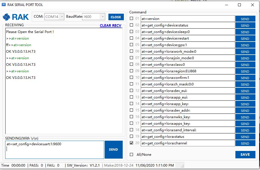
I then used the RAK Serial Port Tool to see if the configuration had changed
OK Work Mode: LoRaWAN
Region: AS923
Send_interval: 600s
Auto send status: false.
Join_mode: OTAA
DevEui: ...
AppEui: ...
AppKey: ...
Class: A
Joined Network:false
IsConfirm: false
AdrEnable: true
EnableRepeaterSupport: false
RX2_CHANNEL_FREQUENCY: 923200000, RX2_CHANNEL_DR:2
RX_WINDOW_DURATION: 3000ms
RECEIVE_DELAY_1: 1000ms
RECEIVE_DELAY_2: 2000ms
JOIN_ACCEPT_DELAY_1: 5000ms
JOIN_ACCEPT_DELAY_2: 6000ms
Current Datarate: 2
Primeval Datarate: 2
ChannelsTxPower: 0
UpLinkCounter: 0
DownLinkCounter: 0
The device reset but the settings appear not to have returned to factory.
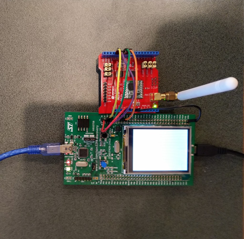
STM32F691Discovery with EVB connected with Jumpers
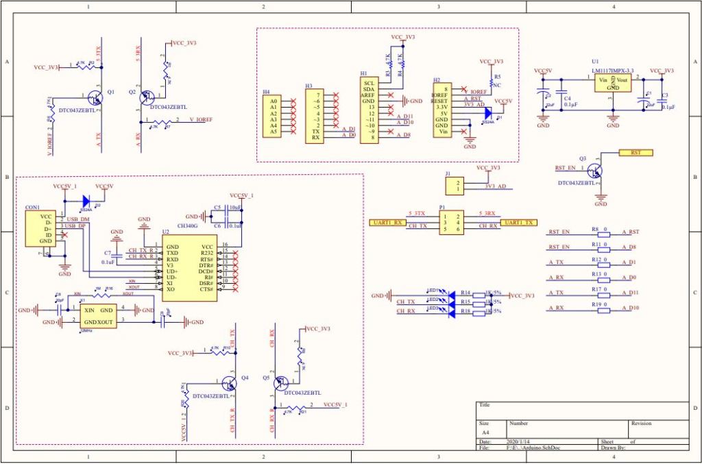
The STM32F691DISCOVERY board has an Arduino Uno R3 format socket which I wanted to be able to plug the EVB into. After removing R8,R17 & R19 I put the EVB on the STM32F691DISCOVERY and could still retrieve the RAK811 module version information.
STM32F691Discovery with EVB plugged into Arduino headers
The thread '<No Name>' (0x2) has exited with code 0 (0x0).
devMobile.IoT.Rfm9x.ShieldSerial starting
COM5,COM6
TX: 12 bytes to output stream.
TX: 12 bytes via COM6
RXs :19 bytes read from COM6
RX sync:OK V3.0.0.13.H.T3

TX: 12 bytes to output stream.
TX: 12 bytes via COM6
RXs :19 bytes read from COM6
RX sync:OK V3.0.0.13.H.T3
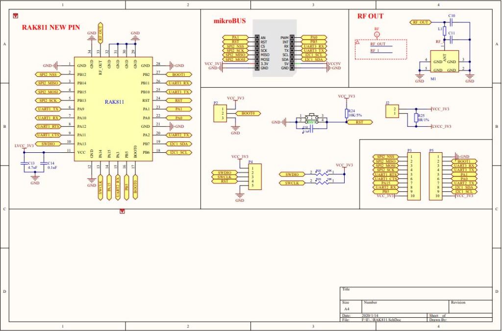
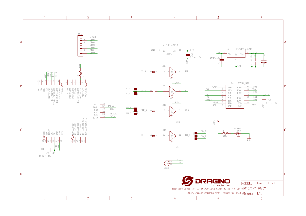
My first step was to check what serial ports were available (COM5 & COM6) on the STM32F691Discovery and what pins they were connected to. (COM6 Arduino D0 & D1). Then check that these would work with the EVB pin assignments.
RAK 811 EVB schematic pg1RAK 811 EVB schematic pg2
My first test was was a simple loopback based on the nanoFramework samples Serial Communications example.
STM32F691Discovery with jumper loopback
//---------------------------------------------------------------------------------
// Copyright (c) June 2020, devMobile Software
//
// Licensed under the Apache License, Version 2.0 (the "License");
// you may not use this file except in compliance with the License.
// You may obtain a copy of the License at
//
//     http://www.apache.org/licenses/LICENSE-2.0
//
// Unless required by applicable law or agreed to in writing, software
// distributed under the License is distributed on an "AS IS" BASIS,
// WITHOUT WARRANTIES OR CONDITIONS OF ANY KIND, either express or implied.
// See the License for the specific language governing permissions and
// limitations under the License.
//
//---------------------------------------------------------------------------------
//#define ESP32_WROOM   //nanoff --target ESP32_WROOM_32 --serialport COM4 --update
//#define NETDUINO3_WIFI   // nanoff --target NETDUINO3_WIFI --update
//#define MBN_QUAIL // nanoff --target MBN_QUAIL --update
//#define ST_NUCLEO64_F091RC // nanoff --target ST_NUCLEO64_F091RC --update
//#define ST_NUCLEO144_F746ZG //nanoff --target ST_NUCLEO144_F746ZG --update
#define ST_STM32F769I_DISCOVERY      // nanoff --target ST_STM32F769I_DISCOVERY --update
namespace devMobile.IoT.Rak811.ShieldSerial
{
   using System;
   using System.Diagnostics;
   using System.Threading;
   using Windows.Devices.SerialCommunication;
   using Windows.Storage.Streams;

#if ESP32_WROOM_32_LORA_1_CHANNEL
   using nanoFramework.Hardware.Esp32;
#endif

   public class Program
   {
#if ESP32_WROOM
      private const string SerialPortId = "";
#endif
#if NETDUINO3_WIFI
      private const string SpiBusId = "";
#endif
#if MBN_QUAIL
      private const string SpiBusId = "";
#endif
#if ST_NUCLEO64_F091RC
      private const string SpiBusId = "";
#endif
#if ST_NUCLEO144_F746ZG
      private const string SpiBusId = "";
#endif
#if ST_STM32F429I_DISCOVERY
      private const string SpiBusId = "";
#endif
#if ST_STM32F769I_DISCOVERY
      private const string SerialPortId = "COM6";
#endif

      public static void Main()
      {
         SerialDevice serialDevice;

         Debug.WriteLine("devMobile.IoT.Rfm9x.ShieldSerial starting");

         Debug.WriteLine(Windows.Devices.SerialCommunication.SerialDevice.GetDeviceSelector());

         try
         {
            // set GPIO functions for COM2 (this is UART1 on ESP32)
            #if ESP32_WROOM
               Configuration.SetPinFunction(Gpio.IO04, DeviceFunction.COM2_TX);
               Configuration.SetPinFunction(Gpio.IO05, DeviceFunction.COM2_RX);
            #endif
            serialDevice = SerialDevice.FromId(SerialPortId);

            // set parameters
            serialDevice.BaudRate = 9600;
            serialDevice.Parity = SerialParity.None;
            serialDevice.StopBits = SerialStopBitCount.One;
            serialDevice.Handshake = SerialHandshake.None;
            serialDevice.DataBits = 8;

            serialDevice.ReadTimeout = new TimeSpan(0, 0, 30);
            serialDevice.WriteTimeout = new TimeSpan(0, 0, 4);

            DataWriter outputDataWriter = new DataWriter(serialDevice.OutputStream);

            #if SERIAL_SYNC_READ
               DataReader inputDataReader = new DataReader(serialDevice.InputStream);
            #else
               serialDevice.DataReceived += SerialDevice_DataReceived;
            #endif

            // set a watch char to be notified when it's available in the input stream
            serialDevice.WatchChar = '\n';

            while (true)
            {
               uint bytesWritten = outputDataWriter.WriteString("at+version\r\n");
               Debug.WriteLine($"TX: {outputDataWriter.UnstoredBufferLength} bytes to output stream.");

               // calling the 'Store' method on the data writer actually sends the data
               uint txByteCount = outputDataWriter.Store();
               Debug.WriteLine($"TX: {txByteCount} bytes via {serialDevice.PortName}");

#if SERIAL_SYNC_READ
               uint bytesRead = inputDataReader.Load(50);

               Debug.WriteLine($"RXs :{bytesRead} bytes read from {serialDevice.PortName}");

               if (bytesRead > 0)
               {
                  String response = inputDataReader.ReadString(bytesRead);
                  Debug.WriteLine($"RX sync:{response}");
               }
#endif

               Thread.Sleep(20000);
            }
         }
         catch (Exception ex)
         {
            Debug.WriteLine(ex.Message);
         }
      }

      private static void SerialDevice_DataReceived(object sender, SerialDataReceivedEventArgs e)
      {
         switch(e.EventType)
         {
            case SerialData.Chars:
               //Debug.WriteLine("RX SerialData.Chars");
               break;

            case SerialData.WatchChar:
               Debug.WriteLine("RX: SerialData.WatchChar");
               SerialDevice serialDevice = (SerialDevice)sender;

               using (DataReader inputDataReader = new DataReader(serialDevice.InputStream))
               {
                  inputDataReader.InputStreamOptions = InputStreamOptions.Partial;

                  // read all available bytes from the Serial Device input stream
                  uint bytesRead = inputDataReader.Load(serialDevice.BytesToRead);

                  Debug.WriteLine($"RXa: {bytesRead} bytes read from {serialDevice.PortName}");

                  if (bytesRead > 0)
                  {
                     String response = inputDataReader.ReadString(bytesRead);
                     Debug.WriteLine($"RX:{response}");
                  }
               }
               break;
            default:
               Debug.Assert(false, $"e.EventType {e.EventType} unknown");
               break;
         }
      }
   }
}
After some tinkering I could successfully transmit and receive a string.
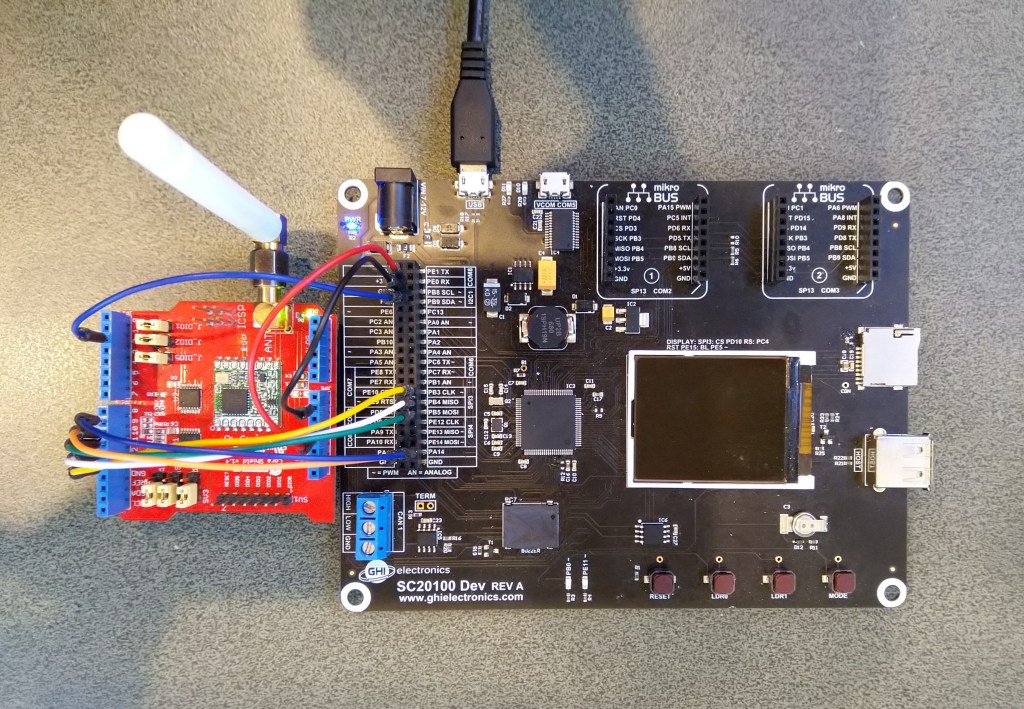
The next step was to connect my EVB and sent the AT Command to request the LoRaWAN module version information
STM32F691Discovery with EVB connected with Jumpers
The thread '<No Name>' (0x2) has exited with code 0 (0x0).
devMobile.IoT.Rfm9x.ShieldSerial starting
COM5,COM6
TX: 12 bytes to output stream.
TX: 12 bytes via COM6
RX: SerialData.WatchChar
RXa: 19 bytes read from COM6
RX:OK V3.0.0.13.H.T3

TX: 12 bytes to output stream.
TX: 12 bytes via COM6
RX: SerialData.WatchChar
RXa: 19 bytes read from COM6
RX:OK V3.0.0.13.H.T3
The response was the same as I got with the RAK Serial Port Tool which was positive.
Version number check with RAK Serial Port tool
I need to do some more digging into how serialDevice.WatchChar = ‘\n’ works for synchronous reads.
Plus removing R17 & R19 there is no interaction with D11 & D10 which are normally used by the Serial Peripheral Interface(SPI) port so I can plug the shield directly into the STM32F691Discovery board.
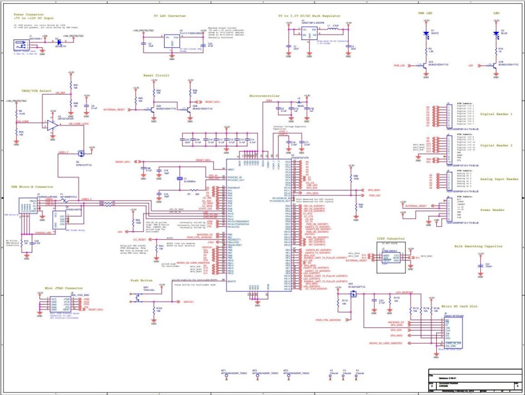
My plan was to get an initial version of the library working with the STM32F691Discovery, then port it to the Netduino 3 Wifi (possible serial port pin issues) , ST_NUCLEO144_F746ZG, and ST_NUCLEO64_F091RC (possible issues with available flash).
The first step was to figure out the configuration using the 00.Shield project. After some experimentation I figured out the SPI port connected to D10-D13 was SPI2 (SPI1 is connected to the MicroSD port)
//---------------------------------------------------------------------------------
// Copyright (c) April 2020, devMobile Software
//
// Licensed under the Apache License, Version 2.0 (the "License");
// you may not use this file except in compliance with the License.
// You may obtain a copy of the License at
//
//     http://www.apache.org/licenses/LICENSE-2.0
//
// Unless required by applicable law or agreed to in writing, software
// distributed under the License is distributed on an "AS IS" BASIS,
// WITHOUT WARRANTIES OR CONDITIONS OF ANY KIND, either express or implied.
// See the License for the specific language governing permissions and
// limitations under the License.
//
//---------------------------------------------------------------------------------
//#define ESP32_WROOM_32_LORA_1_CHANNEL   //nanoff --target ESP32_WROOM_32 --serialport COM4 --update
#define NETDUINO3_WIFI   // nanoff --target NETDUINO3_WIFI --update
//NOTE May 2020 ST_NUCLEO64_F091RC device doesn't work something broken in SPI configuration
//#define ST_NUCLEO64_F091RC // nanoff --target ST_NUCLEO64_F091RC --update
//#define ST_STM32F429I_DISCOVERY       //nanoff --target ST_STM32F429I_DISCOVERY --update
//NOTE May 2020 ST_STM32F769I_DISCOVERY device doesn't work SPI2 mappings broken
//#define ST_STM32F769I_DISCOVERY      // nanoff --target ST_STM32F769I_DISCOVERY --update
namespace devMobile.IoT.Rfm9x.ShieldSPI
{
   using System;
   using System.Diagnostics;
   using System.Threading;

   using Windows.Devices.Gpio;
   using Windows.Devices.Spi;

#if ESP32_WROOM_32_LORA_1_CHANNEL
   using nanoFramework.Hardware.Esp32;
#endif

   public class Program
   {
      private const byte RegVersion = 0x42;
#if ESP32_WROOM_32_LORA_1_CHANNEL
      private const string SpiBusId = "SPI1";
#endif
#if NETDUINO3_WIFI
      private const string SpiBusId = "SPI2";
#endif
#if ST_NUCLEO64_F091RC
      private const string SpiBusId = "SPI1";
#endif
#if ST_STM32F429I_DISCOVERY
      private const string SpiBusId = "SPI5";
#endif
#if ST_STM32F769I_DISCOVERY
      private const string SpiBusId = "SPI5";
#endif

      public static void Main()
      {
#if ESP32_WROOM_32_LORA_1_CHANNEL // No reset line for this device as it isn't connected on SX127X
         int ledPinNumber = Gpio.IO17;
         int chipSelectPinNumber = Gpio.IO16;
#endif
#if NETDUINO3_WIFI
         int ledPinNumber  = PinNumber('A', 10);
         // Arduino D10->PB10
         int chipSelectPinNumber = PinNumber('B', 10);
         // Arduino D9->PE5
         int resetPinNumber = PinNumber('E', 5);
#endif
#if ST_NUCLEO64_F091RC // No LED for this device as driven by D13 the SPI CLK line
         // Arduino D10->PB6
         int chipSelectPinNumber = PinNumber('B', 6);
         // Arduino D9->PC7
         int resetPinNumber = PinNumber('C', 7);
#endif
#if ST_STM32F429I_DISCOVERY // No reset line for this device as I didn't bother with jumper to SX127X pin
         int ledPinNumber  = PinNumber('G', 14);
         int chipSelectPinNumber = PinNumber('C', 2);
#endif
#if ST_STM32F769I_DISCOVERY
         int ledPinNumber  = PinNumber('J', 5);
         // Arduino D10->PA11
         int chipSelectPinNumber = PinNumber('A', 11);
         // Arduino D9->PH6
         int resetPinNumber = PinNumber('H', 6);
#endif
         Debug.WriteLine("devMobile.IoT.Rfm9x.ShieldSPI starting");

         try
         {
            GpioController gpioController = GpioController.GetDefault();

#if NETDUINO3_WIFI|| ST_NUCLEO64_F091RC || ST_STM32F769I_DISCOVERY
            // Setup the reset pin
            GpioPin resetGpioPin = gpioController.OpenPin(resetPinNumber);
            resetGpioPin.SetDriveMode(GpioPinDriveMode.Output);
            resetGpioPin.Write(GpioPinValue.High);
#endif

#if ESP32_WROOM_32_LORA_1_CHANNEL || NETDUINO3_WIFI|| ST_STM32F429I_DISCOVERY || ST_STM32F769I_DISCOVERY
            // Setup the onboard LED
            GpioPin led = gpioController.OpenPin(ledPinNumber);
            led.SetDriveMode(GpioPinDriveMode.Output);
#endif

#if ESP32_WROOM_32_LORA_1_CHANNEL
            Configuration.SetPinFunction(nanoFramework.Hardware.Esp32.Gpio.IO12, DeviceFunction.SPI1_MISO);
            Configuration.SetPinFunction(nanoFramework.Hardware.Esp32.Gpio.IO13, DeviceFunction.SPI1_MOSI);
            Configuration.SetPinFunction(nanoFramework.Hardware.Esp32.Gpio.IO14, DeviceFunction.SPI1_CLOCK);
#endif

            var settings = new SpiConnectionSettings(chipSelectPinNumber)
            {
               ClockFrequency = 500000,
               Mode = SpiMode.Mode0,// From SemTech docs pg 80 CPOL=0, CPHA=0
               SharingMode = SpiSharingMode.Shared,
            };

            using (SpiDevice device = SpiDevice.FromId(SpiBusId, settings))
            {
               Thread.Sleep(500);

               while (true)
               {
                  byte[] writeBuffer = new byte[] { RegVersion, 0x0 };
                  byte[] readBuffer = new byte[writeBuffer.Length];

                  device.TransferFullDuplex(writeBuffer, readBuffer);

                  Debug.WriteLine(String.Format("Register 0x{0:x2} - Value 0X{1:x2}", RegVersion, readBuffer[1]));

                  #if ESP32_WROOM_32_LORA_1_CHANNEL|| NETDUINO3_WIFI || ST_STM32F429I_DISCOVERY || ST_STM32F769I_DISCOVERY
                     led.Toggle();
                  #endif
                  Thread.Sleep(10000);
               }
            }
         }
         catch (Exception ex)
         {
            Debug.WriteLine(ex.Message);
         }
      }

#if  NETDUINO3_WIFI || ST_NUCLEO64_F091RC || ST_STM32F429I_DISCOVERY || ST_STM32F769I_DISCOVERY
      static int PinNumber(char port, byte pin)
      {
         if (port < 'A' || port > 'J')
            throw new ArgumentException();

         return ((port - 'A') * 16) + pin;
      }
#endif
   }
}
In the Visual Studio output windows I could see the correct version register value
The thread '<No Name>' (0x2) has exited with code 0 (0x0).
devMobile.IoT.Rfm9x.ShieldSPI starting
Register 0x42 - Value 0X12
Register 0x42 - Value 0X12
...
After checking the configuration of the reset (D9) and interrupt (D2) pins in other test harness programs my final configuration for Rfm9xLoRaDevice client was
//---------------------------------------------------------------------------------
// Copyright (c) April/May 2020, devMobile Software
//
// Licensed under the Apache License, Version 2.0 (the "License");
// you may not use this file except in compliance with the License.
// You may obtain a copy of the License at
//
//     http://www.apache.org/licenses/LICENSE-2.0
//
// Unless required by applicable law or agreed to in writing, software
// distributed under the License is distributed on an "AS IS" BASIS,
// WITHOUT WARRANTIES OR CONDITIONS OF ANY KIND, either express or implied.
// See the License for the specific language governing permissions and
// limitations under the License.
//
//---------------------------------------------------------------------------------
//#define ADDRESSED_MESSAGES_PAYLOAD
//#define ESP32_WROOM_32_LORA_1_CHANNEL   //nanoff --target ESP32_WROOM_32 --serialport COM4 --update
#define NETDUINO3_WIFI   // nanoff --target NETDUINO3_WIFI --update
//#define ST_STM32F429I_DISCOVERY       //nanoff --target ST_STM32F429I_DISCOVERY --update
namespace devMobile.IoT.Rfm9x.LoRaDeviceClient
{
	using System;
	using System.Diagnostics;
	using System.Text;
	using System.Threading;

#if ESP32_WROOM_32_LORA_1_CHANNEL
	using nanoFramework.Hardware.Esp32;
#endif

	using devMobile.IoT.Rfm9x;

	class Program
	{
		private const double Frequency = 915000000.0;
#if ST_STM32F429I_DISCOVERY
		private const string DeviceName = "Disco429";
		private const string SpiBusId = "SPI5";
#endif
#if ESP32_WROOM_32_LORA_1_CHANNEL
		private const string DeviceName = "ESP32";
		private const string SpiBusId = "SPI1";
#endif
#if NETDUINO3_WIFI
		private const string DeviceName = "N3W";
		private const string SpiBusId = "SPI2";
#endif
#if ADDRESSED_MESSAGES_PAYLOAD
		private const string DeviceName = "LoRaIoT1";
#endif

		static void Main()
		{
			byte MessageCount = System.Byte.MaxValue;
#if ST_STM32F429I_DISCOVERY
			int chipSelectPinNumber = PinNumber('C', 2);
			int resetPinNumber = PinNumber('C', 3);
			int interruptPinNumber = PinNumber('A', 4);
#endif
#if ESP32_WROOM_32_LORA_1_CHANNEL
         int chipSelectPinNumber = Gpio.IO16;
         int interruptPinNumber = Gpio.IO26;

			Configuration.SetPinFunction(Gpio.IO12, DeviceFunction.SPI1_MISO);
			Configuration.SetPinFunction(Gpio.IO13, DeviceFunction.SPI1_MOSI);
			Configuration.SetPinFunction(Gpio.IO14, DeviceFunction.SPI1_CLOCK);

			Rfm9XDevice rfm9XDevice = new Rfm9XDevice(SpiBusId, chipSelectPinNumber, interruptPinNumber);
#endif
#if NETDUINO3_WIFI
			// Arduino D10->PB10
			int chipSelectPinNumber = PinNumber('B', 10);
			// Arduino D9->PE5
			int resetPinNumber = PinNumber('E', 5);
			// Arduino D2->PA3
			int interruptPinNumber = PinNumber('A', 3);
#endif

#if ST_STM32F429I_DISCOVERY || NETDUINO3_WIFI
			Rfm9XDevice rfm9XDevice = new Rfm9XDevice(SpiBusId, chipSelectPinNumber, resetPinNumber, interruptPinNumber);
#endif
			rfm9XDevice.Initialise(Frequency, paBoost: true);

#if DEBUG
			rfm9XDevice.RegisterDump();
#endif

			rfm9XDevice.OnReceive += Rfm9XDevice_OnReceive;
#if ADDRESSED_MESSAGES_PAYLOAD
			rfm9XDevice.Receive(UTF8Encoding.UTF8.GetBytes(DeviceName));
#else
			rfm9XDevice.Receive();
#endif
			rfm9XDevice.OnTransmit += Rfm9XDevice_OnTransmit;

			Thread.Sleep(10000);

			while (true)
			{
				string messageText = string.Format("Hello from {0} ! {1}", DeviceName, MessageCount);
				MessageCount -= 1;

				byte[] messageBytes = UTF8Encoding.UTF8.GetBytes(messageText);
				Debug.WriteLine(string.Format("{0}-TX {1} byte message {2}", DateTime.UtcNow.ToString("HH:mm:ss"), messageBytes.Length, messageText));
#if ADDRESSED_MESSAGES_PAYLOAD
				rfm9XDevice.Send(UTF8Encoding.UTF8.GetBytes(HostName), messageBytes);
#else
				rfm9XDevice.Send(messageBytes);
#endif
				Thread.Sleep(10000);
			}
		}

		private static void Rfm9XDevice_OnReceive(object sender, Rfm9XDevice.OnDataReceivedEventArgs e)
		{
			try
			{
				// Remove unprintable characters from messages
				for (int index = 0; index < e.Data.Length; index++)
				{
					if ((e.Data[index] < 0x20) || (e.Data[index] > 0x7E))
					{
						e.Data[index] = 0x20;
					}
				}

				string messageText = UTF8Encoding.UTF8.GetString(e.Data, 0, e.Data.Length);

#if ADDRESSED_MESSAGES_PAYLOAD
				string addressText = UTF8Encoding.UTF8.GetString(e.Address, 0, e.Address.Length);

				Debug.WriteLine(string.Format(@"{0}-RX From {1} PacketSnr {2} Packet RSSI {3}dBm RSSI {4}dBm ={5} ""{6}""", DateTime.UtcNow.ToString("HH:mm:ss"), addressText, e.PacketSnr, e.PacketRssi, e.Rssi, e.Data.Length, messageText));
#else
				Debug.WriteLine(string.Format(@"{0}-RX PacketSnr {1} Packet RSSI {2}dBm RSSI {3}dBm ={4} ""{5}""", DateTime.UtcNow.ToString("HH:mm:ss"), e.PacketSnr, e.PacketRssi, e.Rssi, e.Data.Length, messageText));
#endif
			}
			catch (Exception ex)
			{
				Debug.WriteLine(ex.Message);
			}
		}

		private static void Rfm9XDevice_OnTransmit(object sender, Rfm9XDevice.OnDataTransmitedEventArgs e)
		{
			Debug.WriteLine(string.Format("{0}-TX Done", DateTime.UtcNow.ToString("HH:mm:ss")));
		}

#if ST_STM32F429I_DISCOVERY || NETDUINO3_WIFI
		static int PinNumber(char port, byte pin)
      {
         if (port < 'A' || port > 'J')
            throw new ArgumentException();

         return ((port - 'A') * 16) + pin;
      }
#endif
	}
}
The sample client could reliable send and receive messages.
The thread '<No Name>' (0x2) has exited with code 0 (0x0).
Register dump
Register 0x00 - Value 0X7A
Register 0x01 - Value 0X80
Register 0x02 - Value 0X1A
Register 0x03 - Value 0X0B
Register 0x04 - Value 0X00
Register 0x05 - Value 0X52
Register 0x06 - Value 0XE4
Register 0x07 - Value 0XC0
Register 0x08 - Value 0X00
Register 0x09 - Value 0XCF
Register 0x0A - Value 0X09
Register 0x0B - Value 0X2B
Register 0x0C - Value 0X20
Register 0x0D - Value 0X01
Register 0x0E - Value 0X80
Register 0x0F - Value 0X00
Register 0x10 - Value 0X00
Register 0x11 - Value 0X00
Register 0x12 - Value 0X00
Register 0x13 - Value 0X00
Register 0x14 - Value 0X00
Register 0x15 - Value 0X00
Register 0x16 - Value 0X00
Register 0x17 - Value 0X00
Register 0x18 - Value 0X10
Register 0x19 - Value 0X00
Register 0x1A - Value 0X00
Register 0x1B - Value 0X00
Register 0x1C - Value 0X00
Register 0x1D - Value 0X72
Register 0x1E - Value 0X70
Register 0x1F - Value 0X64
Register 0x20 - Value 0X00
Register 0x21 - Value 0X08
Register 0x22 - Value 0X01
Register 0x23 - Value 0XFF
Register 0x24 - Value 0X00
Register 0x25 - Value 0X00
Register 0x26 - Value 0X04
Register 0x27 - Value 0X00
Register 0x28 - Value 0X00
Register 0x29 - Value 0X00
Register 0x2A - Value 0X00
Register 0x2B - Value 0X00
Register 0x2C - Value 0X00
Register 0x2D - Value 0X50
Register 0x2E - Value 0X14
Register 0x2F - Value 0X45
Register 0x30 - Value 0X55
Register 0x31 - Value 0XC3
Register 0x32 - Value 0X05
Register 0x33 - Value 0X27
Register 0x34 - Value 0X1C
Register 0x35 - Value 0X0A
Register 0x36 - Value 0X03
Register 0x37 - Value 0X0A
Register 0x38 - Value 0X42
Register 0x39 - Value 0X12
Register 0x3A - Value 0X49
Register 0x3B - Value 0X1D
Register 0x3C - Value 0X00
Register 0x3D - Value 0XAF
Register 0x3E - Value 0X00
Register 0x3F - Value 0X00
Register 0x40 - Value 0X00
Register 0x41 - Value 0X00
Register 0x42 - Value 0X12
00:00:25-TX 20 byte message Hello from N3W ! 255
00:00:25-TX Done
00:00:35-TX 20 byte message Hello from N3W ! 254
00:00:35-TX Done
00:00:45-TX 20 byte message Hello from N3W ! 253
00:00:45-TX Done
00:00:46-RX PacketSnr 9.50 Packet RSSI -70dBm RSSI -110dBm =59 " LoRaIoT1Maduino2at 43.9,ah 75,wsa 1,wsg 2,wd 36.00,r 0.00,"
00:00:55-TX 20 byte message Hello from N3W ! 252
00:00:55-TX Done
00:01:05-TX 20 byte message Hello from N3W ! 251
00:01:05-TX Done
Overall the process was fairly painless and helped identify a bug in the configuration of the Mode register in one of the test harness applications.
For the final revision my nanoFrameworkSX127X Library test harness I checked interrupts were working for the interleaved transmission and reception of messages.
      private void InterruptGpioPin_ValueChanged(object sender, GpioPinValueChangedEventArgs e)
      {
         if (e.Edge != GpioPinEdge.RisingEdge)
         {
            return;
         }

         byte irqFlags = this.RegisterReadByte(0x12); // RegIrqFlags
         Console.WriteLine($"RegIrqFlags 0X{irqFlags:x2}");

         if ((irqFlags & 0b01000000) == 0b01000000)  // RxDone
         {
            Console.WriteLine("Receive-Message");
            byte currentFifoAddress = this.RegisterReadByte(0x10); // RegFifiRxCurrent
            this.RegisterWriteByte(0x0d, currentFifoAddress); // RegFifoAddrPtr

            byte numberOfBytes = this.RegisterReadByte(0x13); // RegRxNbBytes

            // Allocate buffer for message
            byte[] messageBytes = this.RegisterRead(0X0, numberOfBytes);

            // Remove unprintable characters from messages
            for (int index = 0; index < messageBytes.Length; index++)
            {
               if ((messageBytes[index] < 0x20) || (messageBytes[index] > 0x7E))
               {
                  messageBytes[index] = 0x20;
               }
            }

            string messageText = UTF8Encoding.UTF8.GetString(messageBytes,0, messageBytes.Length);
            Console.WriteLine($"Received {messageBytes.Length} byte message {messageText}");
         }

         if ((irqFlags & 0b00001000) == 0b00001000)  // TxDone
         {
            this.RegisterWriteByte(0x01, 0b10000101); // RegOpMode set LoRa & RxContinuous
            Console.WriteLine("Transmit-Done");
         }

         this.RegisterWriteByte(0x40, 0b00000000); // RegDioMapping1 0b00000000 DI0 RxReady & TxReady
         this.RegisterWriteByte(0x12, 0xff);// RegIrqFlags
      }

…
class Program
{
      static void Main()
      {
         int SendCount = 0;
#if ST_STM32F429I_DISCOVERY
         int chipSelectPinNumber = PinNumber('C', 2);
         int resetPinNumber = PinNumber('C', 3);
         int interruptPinNumber = PinNumber('A', 4);
#endif
#if ESP32_WROOM_32_LORA_1_CHANNEL
         int chipSelectPinNumber = Gpio.IO16;
         int interruptPinNumber = Gpio.IO26;
#endif

         try
         {
#if ESP32_WROOM_32_LORA_1_CHANNEL
            Configuration.SetPinFunction(Gpio.IO12, DeviceFunction.SPI1_MISO);
            Configuration.SetPinFunction(Gpio.IO13, DeviceFunction.SPI1_MOSI);
            Configuration.SetPinFunction(Gpio.IO14, DeviceFunction.SPI1_CLOCK);
            Rfm9XDevice rfm9XDevice = new Rfm9XDevice(SpiBusId, chipSelectPinNumber, interruptPinNumber);
#endif
#if ST_STM32F429I_DISCOVERY
            Rfm9XDevice rfm9XDevice = new Rfm9XDevice(SpiBusId, chipSelectPinNumber, resetPinNumber, interruptPinNumber);
#endif
            Thread.Sleep(500);

            // Put device into LoRa + Standby mode
            rfm9XDevice.RegisterWriteByte(0x01, 0b10000000); // RegOpMode

            // Set the frequency to 915MHz
            byte[] frequencyWriteBytes = { 0xE4, 0xC0, 0x00 }; // RegFrMsb, RegFrMid, RegFrLsb
            rfm9XDevice.RegisterWrite(0x06, frequencyWriteBytes);

            // More power PA Boost
            rfm9XDevice.RegisterWriteByte(0x09, 0b10000000); // RegPaConfig

            // Interrupt on TxDone
            rfm9XDevice.RegisterWriteByte(0x40, 0b01000000); // RegDioMapping1 0b00000000 DI0 TxDone

            while (true)
            {
               // Set the Register Fifo address pointer
               rfm9XDevice.RegisterWriteByte(0x0E, 0x00); // RegFifoTxBaseAddress

               // Set the Register Fifo address pointer
               rfm9XDevice.RegisterWriteByte(0x0D, 0x0); // RegFifoAddrPtr

               string messageText = $"Hello LoRa {SendCount += 1}!";

               // load the message into the fifo
               byte[] messageBytes = UTF8Encoding.UTF8.GetBytes(messageText);
               rfm9XDevice.RegisterWrite(0x0, messageBytes); // RegFifo

               // Set the length of the message in the fifo
               rfm9XDevice.RegisterWriteByte(0x22, (byte)messageBytes.Length); // RegPayloadLength
               Console.WriteLine($"Sending {messageBytes.Length} bytes message {messageText}");
               rfm9XDevice.RegisterWriteByte(0x01, 0b10000011); // RegOpMode

               Thread.Sleep(10000);
            }
         }
         catch (Exception ex)
         {
            Console.WriteLine(ex.Message);
         }
      }
The diagnostic output shows inbound and outbound messages
This code implements the reception of messages builds on my transmit basic sample. I had to add a simple for loop to replace un-printable characters in the received message with spaces as nanoFrameworkUTF8Encoding.UTF8.GetString was throwing exceptions.
For the final revision of the “nasty” test harness I ensured interrupts were working for the simultaneous transmission and reception of messages. It’s not quite simultaneous, the code sends a message every 10 seconds then goes back to receive continuous mode after each message has been sent.
private void InterruptGpioPin_ValueChanged(GpioPin sender, GpioPinValueChangedEventArgs e)
{
   if (e.Edge != GpioPinEdge.RisingEdge)
   {
      return;
   }

   byte irqFlags = this.RegisterReadByte(0x12); // RegIrqFlags
   Debug.WriteLine($"RegIrqFlags 0X{irqFlags:x2}");

   if ((irqFlags & 0b01000000) == 0b01000000)  // RxDone
   {
      Debug.WriteLine("Receive-Message");
      byte currentFifoAddress = this.RegisterReadByte(0x10); // RegFifiRxCurrent
      this.RegisterWriteByte(0x0d, currentFifoAddress); // RegFifoAddrPtr

      byte numberOfBytes = this.RegisterReadByte(0x13); // RegRxNbBytes

      // Allocate buffer for message
      byte[] messageBytes = this.RegisterRead(0X0, numberOfBytes);

      string messageText = UTF8Encoding.UTF8.GetString(messageBytes);
      Debug.WriteLine($"Received {messageBytes.Length} byte message {messageText}");
   }

  if ((irqFlags & 0b00001000) == 0b00001000)  // TxDone
  {
      this.RegisterWriteByte(0x01, 0b10000101); // RegOpMode set LoRa & RxContinuous
      Debug.WriteLine("Transmit-Done");
  }

   this.RegisterWriteByte(0x40, 0b00000000); // RegDioMapping1 0b00000000 DI0 RxReady & TxReady
   this.RegisterWriteByte(0x12, 0xff);// RegIrqFlags
}
…
class Program
{
   static void Main()
   {
      Rfm9XDevice rfm9XDevice = new Rfm9XDevice(SC20100.SpiBus.Spi3, SC20100.GpioPin.PA13, SC20100.GpioPin.PA14, SC20100.GpioPin.PE4);
      int sendCount = 0;

      // Put device into LoRa + Sleep mode
      rfm9XDevice.RegisterWriteByte(0x01, 0b10000000); // RegOpMode

      // Set the frequency to 915MHz
      byte[] frequencyWriteBytes = { 0xE4, 0xC0, 0x00 }; // RegFrMsb, RegFrMid, RegFrLsb
      rfm9XDevice.RegisterWrite(0x06, frequencyWriteBytes);

      rfm9XDevice.RegisterWriteByte(0x0F, 0x0); // RegFifoRxBaseAddress

      // More power PA Boost
      rfm9XDevice.RegisterWriteByte(0x09, 0b10000000); // RegPaConfig

      rfm9XDevice.RegisterWriteByte(0x01, 0b10000101); // RegOpMode set LoRa & RxContinuous

      while (true)
      {
         rfm9XDevice.RegisterWriteByte(0x0E, 0x0); // RegFifoTxBaseAddress

         // Set the Register Fifo address pointer
         rfm9XDevice.RegisterWriteByte(0x0D, 0x0); // RegFifoAddrPtr

         string messageText = $"Hello LoRa {sendCount += 1}!";

         // load the message into the fifo
         byte[] messageBytes = UTF8Encoding.UTF8.GetBytes(messageText);
         rfm9XDevice.RegisterWrite(0x0, messageBytes); // RegFifo

         // Set the length of the message in the fifo
         rfm9XDevice.RegisterWriteByte(0x22, (byte)messageBytes.Length); // RegPayloadLength
         rfm9XDevice.RegisterWriteByte(0x40, 0b01000000); // RegDioMapping1 0b00000000 DI0 RxReady & TxReady
         rfm9XDevice.RegisterWriteByte(0x01, 0b10000011); // RegOpMode

         Debug.WriteLine($"Sending {messageBytes.Length} bytes message {messageText}");

         Thread.Sleep(10000);
      }
   }
}
The diagnostic output shows inbound and outbound messages