AdaFruit IO basic Netduino HTTP client

I use Netduino devices for teaching and my students often build projects which need a cloud based service like AdaFruit.IO to capture, store and display their sensor data.

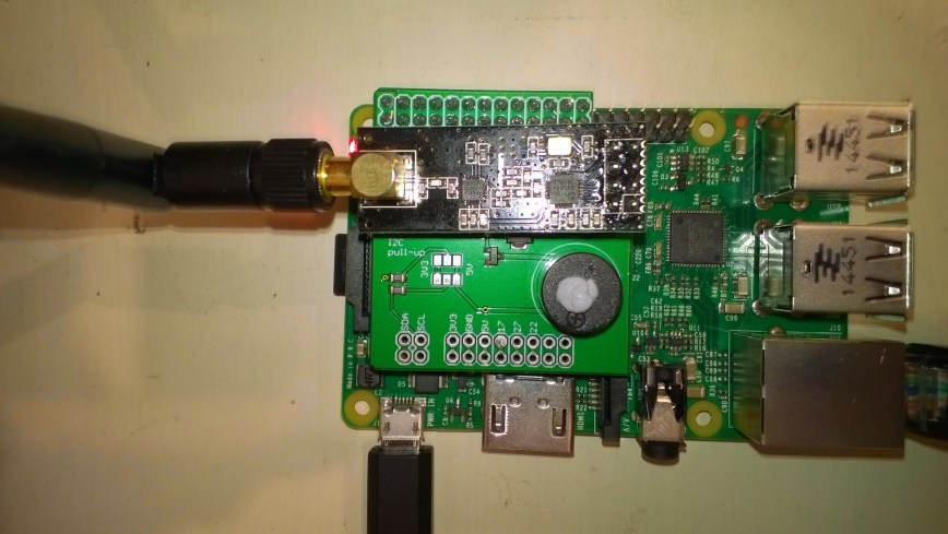
My Proof of Concept (PoC) which uses a slightly modified version of the AdaFruit.IO basic desktop HTTP client code has been running on several Netduino 2 Plus, Netduino 3 Ethernet and Netduino 3 Wifi devices for the last couple of days and looks pretty robust.

The Netduino 3 Wifi device also supports https for improved security and privacy. They also make great field gateways as they can run off solar/battery power.

N2PN3WDashBoard

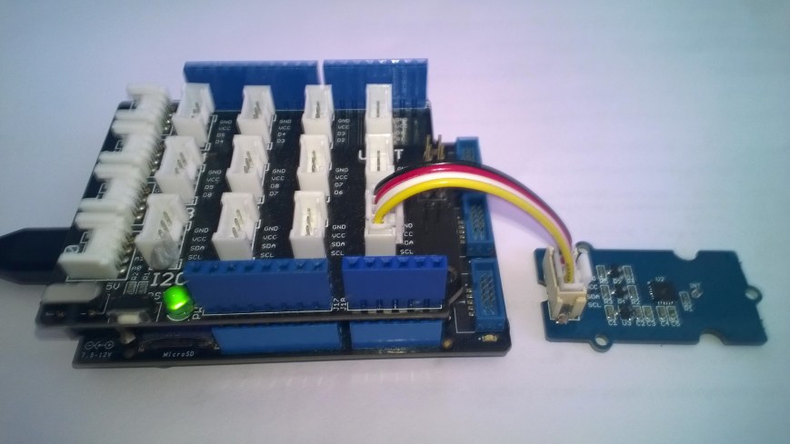
The devices have been uploading temperature and humidity measurements from a Silicon labs Si7005 sensor. (Outside sensor suffering from sunstrike)

N3WifiTemperatureAndHumiditySensor

program.cs

*

Copyright ® 2017 December devMobile Software, All Rights Reserved

THIS CODE AND INFORMATION IS PROVIDED "AS IS" WITHOUT WARRANTY OF ANY
KIND, EITHER EXPRESSED OR IMPLIED, INCLUDING BUT NOT LIMITED TO THE
IMPLIED WARRANTIES OF MERCHANTABILITY AND/OR FITNESS FOR A PARTICULAR
PURPOSE.

http://www.devmobile.co.nz

*/
using System;
using System.Net;
using System.Threading;
using Microsoft.SPOT;
using Microsoft.SPOT.Hardware;
using Microsoft.SPOT.Net.NetworkInformation;
using SecretLabs.NETMF.Hardware.Netduino;
using devMobile.NetMF.Sensor;
using devMobile.IoT.NetMF;

namespace devMobile.IoT.AdaFruitIO.NetMF.Client
{
public class Program
{
private const string adaFruitIOApiBaseUrl = @"https://IO.adafruit.com/api/v2/";
private const string group = "netduino3";
private const string temperatureFeedKey = "t";
private const string humidityFeedKey = "h";
private const string adaFruitUserName = "YourUserName";
private const string adaFruitIOApiKey = "YourAPIKey";
private static readonly TimeSpan timerDueAfter = new TimeSpan(0, 0, 15);
private static readonly TimeSpan timerPeriod = new TimeSpan(0, 0, 30);
private static OutputPort led = new OutputPort(Pins.ONBOARD_LED, false);
private static SiliconLabsSI7005 sensor = new SiliconLabsSI7005();
private static AdaFruitIoClient adaFruitIoClient = new AdaFruitIoClient(adaFruitUserName, adaFruitIOApiKey, adaFruitIOApiBaseUrl);

public static void Main()
{
// Wait for Network address if DHCP
NetworkInterface networkInterface = NetworkInterface.GetAllNetworkInterfaces()[0];
if (networkInterface.IsDhcpEnabled)
{
Debug.Print(" Waiting for DHCP IP address");

while (NetworkInterface.GetAllNetworkInterfaces()[0].IPAddress == IPAddress.Any.ToString())
{
Debug.Print(" .");
led.Write(!led.Read());
Thread.Sleep(250);
}
led.Write(false);
}

// Display network config for debugging
Debug.Print("Network configuration");
Debug.Print(" Network interface type : " + networkInterface.NetworkInterfaceType.ToString());
Debug.Print(" MAC Address : " + BytesToHexString(networkInterface.PhysicalAddress));
Debug.Print(" DHCP enabled : " + networkInterface.IsDhcpEnabled.ToString());
Debug.Print(" Dynamic DNS enabled : " + networkInterface.IsDynamicDnsEnabled.ToString());
Debug.Print(" IP Address : " + networkInterface.IPAddress.ToString());
Debug.Print(" Subnet Mask : " + networkInterface.SubnetMask.ToString());
Debug.Print(" Gateway : " + networkInterface.GatewayAddress.ToString());

foreach (string dnsAddress in networkInterface.DnsAddresses)
{
Debug.Print(" DNS Server : " + dnsAddress.ToString());
}

Timer humidityAndtemperatureUpdates = new Timer(HumidityAndTemperatureTimerProc, null, timerDueAfter, timerPeriod);

Thread.Sleep(Timeout.Infinite);
}

static private void HumidityAndTemperatureTimerProc(object state)
{
led.Write(true);

try
{
double humidity = sensor.Humidity();

Debug.Print(" Humidity " + humidity.ToString("F0") + "%");
adaFruitIoClient.FeedUpdate(group, humidityFeedKey, humidity.ToString("F0"));
}
catch (Exception ex)
{
Debug.Print("Humidifty read+update failed " + ex.Message);

return;
}

try
{
double temperature = sensor.Temperature();

Debug.Print(" Temperature " + temperature.ToString("F1") + "°C");
adaFruitIoClient.FeedUpdate(group, temperatureFeedKey, temperature.ToString("F1"));
}
catch (Exception ex)
{
Debug.Print("Temperature read+update failed " + ex.Message);

return;
}

led.Write(false);
}

private static string BytesToHexString(byte[] bytes)
{
string hexString = string.Empty;

// Create a character array for hexidecimal conversion.
const string hexChars = "0123456789ABCDEF";

// Loop through the bytes.
for (byte b = 0; b < bytes.Length; b++)          {             if (b > 0)
hexString += "-";

// Grab the top 4 bits and append the hex equivalent to the return string.
hexString += hexChars[bytes[b] >> 4];

// Mask off the upper 4 bits to get the rest of it.
hexString += hexChars[bytes[b] & 0x0F];
}

return hexString;
}
}
}

AdaFruit.IO client.cs, handles feed groups and individual feeds

/*

Copyright ® 2017 December devMobile Software, All Rights Reserved

THIS CODE AND INFORMATION IS PROVIDED "AS IS" WITHOUT WARRANTY OF ANY
KIND, EITHER EXPRESSED OR IMPLIED, INCLUDING BUT NOT LIMITED TO THE
IMPLIED WARRANTIES OF MERCHANTABILITY AND/OR FITNESS FOR A PARTICULAR
PURPOSE.

http://www.devmobile.co.nz

*/
using System;
using System.IO;
using System.Net;
using System.Text;
using Microsoft.SPOT;

namespace devMobile.IoT.NetMF
{
public class AdaFruitIoClient
{
private const string apiBaseUrlDefault = @"http://IO.adafruit.com/api/v2/";
private string apiBaseUrl = "";
private string userName = "";
private string apiKey = "";
private int httpRequestTimeoutmSec;
private int httpRequestReadWriteTimeoutmSec;

public AdaFruitIoClient(string userName, string apiKey, string apiBaseUrl = apiBaseUrlDefault, int httpRequestTimeoutmSec = 2500, int httpRequestReadWriteTimeoutmSec = 5000)
{
this.apiBaseUrl = apiBaseUrl;
this.userName = userName;
this.apiKey = apiKey;
this.httpRequestReadWriteTimeoutmSec = httpRequestReadWriteTimeoutmSec;
this.httpRequestTimeoutmSec = httpRequestTimeoutmSec;
}

public void FeedUpdate(string group, string feedKey, string value)
{
string feedUrl;

if (group.Trim() == string.Empty)
{
feedUrl = apiBaseUrl + userName + @"/feeds/" + feedKey + @"/data";
}
else
{
feedUrl = apiBaseUrl + userName + @"/feeds/" + group.Trim() + "." + feedKey + @"/data";
}

HttpWebRequest request = (HttpWebRequest)WebRequest.Create(feedUrl);
{
string payload = @"{""value"": """ + value + @"""}";
byte[] buffer = Encoding.UTF8.GetBytes(payload);

DateTime httpRequestedStartedAtUtc = DateTime.UtcNow;

request.Method = "POST";
request.ContentLength = buffer.Length;
request.ContentType = @"application/json";
request.Headers.Add("X-AIO-Key", apiKey);
request.KeepAlive = false;
request.Timeout = this.httpRequestTimeoutmSec;
request.ReadWriteTimeout = this.httpRequestReadWriteTimeoutmSec;

using (Stream stream = request.GetRequestStream())
{
stream.Write(buffer, 0, buffer.Length);
}

using (var response = (HttpWebResponse)request.GetResponse())
{
Debug.Print(" Status: " + response.StatusCode + " : " + response.StatusDescription);
}

TimeSpan duration = DateTime.UtcNow - httpRequestedStartedAtUtc;
Debug.Print(" Duration: " + duration.ToString());
}
}
}
}

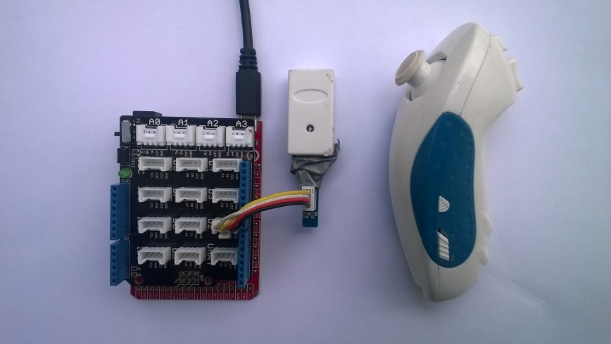
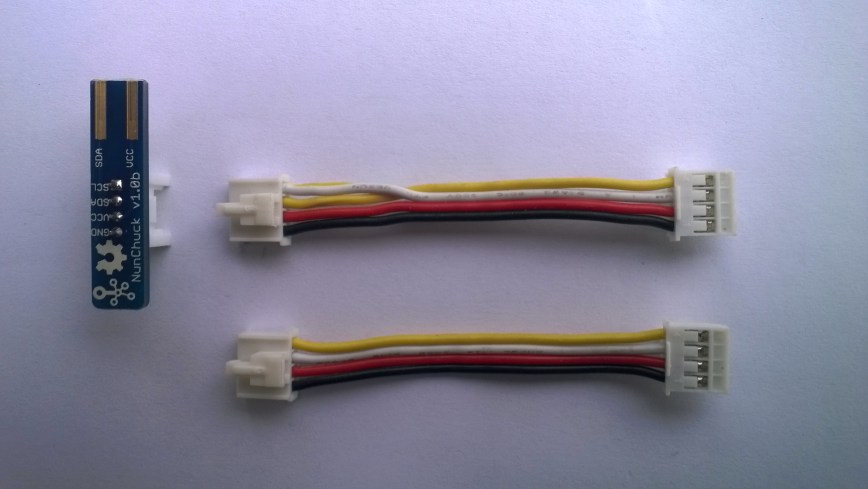
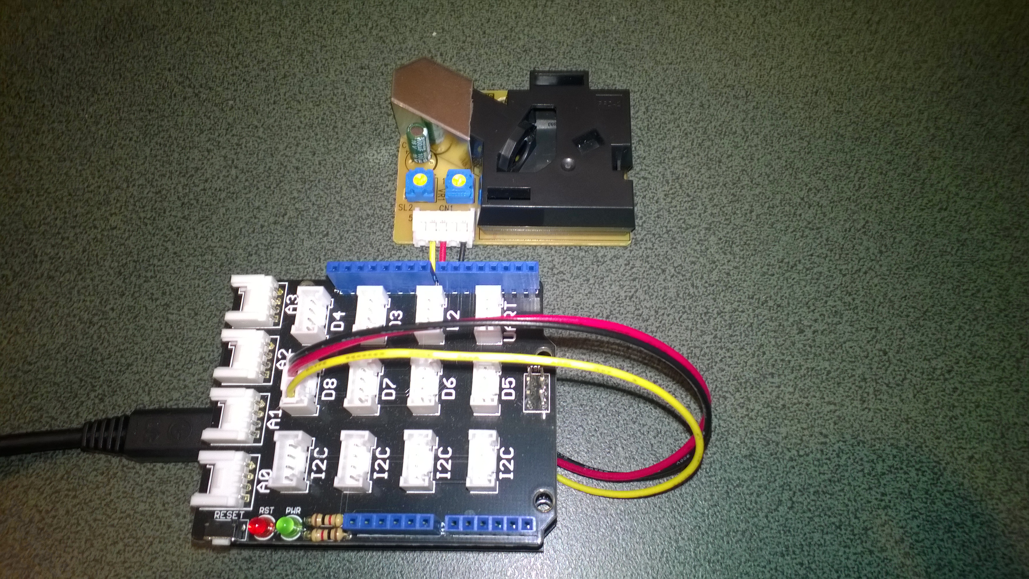
Bill of materials for PoC

nRF24 Windows 10 IoT Core Background Task

First step is to build a basic Windows 10 IoT Core background task which can receive and display messages sent from a variety of devices across an nRF24L01 wireless link.

If you create a new “Windows IoT Core” “Background Application” project then copy this code into StartupTasks.cs the namespace has to be changed in the C# file, project properties\library\Default namespace and “Package.appxmanifest”\declarations\Entry Point.

/*

Copyright ® 2017 December devMobile Software, All Rights Reserved

THIS CODE AND INFORMATION IS PROVIDED "AS IS" WITHOUT WARRANTY OF ANY
KIND, EITHER EXPRESSED OR IMPLIED, INCLUDING BUT NOT LIMITED TO THE
IMPLIED WARRANTIES OF MERCHANTABILITY AND/OR FITNESS FOR A PARTICULAR
PURPOSE.

http://www.devmobile.co.nz

*/
using System;
using System.Diagnostics;
using System.Text;
using Radios.RF24;
using Windows.ApplicationModel.Background;

namespace devmobile.IoTCore.nRF24BackgroundTask
{
    public sealed class StartupTask : IBackgroundTask
    {
      private const byte ChipEnablePin = 25;
      private const byte ChipSelectPin = 0;
      private const byte nRF24InterruptPin = 17;
      private const string BaseStationAddress = "Base1";
      private const byte nRF24Channel = 10;
      private RF24 Radio = new RF24();
      private BackgroundTaskDeferral deferral;

      public void Run(IBackgroundTaskInstance taskInstance)
        {
         Radio.OnDataReceived += Radio_OnDataReceived;
         Radio.OnTransmitFailed += Radio_OnTransmitFailed;
         Radio.OnTransmitSuccess += Radio_OnTransmitSuccess;

         Radio.Initialize(ChipEnablePin, ChipSelectPin, nRF24InterruptPin);
         Radio.Address = Encoding.UTF8.GetBytes(BaseStationAddress);
         Radio.Channel = nRF24Channel;
         Radio.PowerLevel = PowerLevel.High;
         Radio.DataRate = DataRate.DR250Kbps;
         Radio.IsEnabled = true;

         Debug.WriteLine("Address: " + Encoding.UTF8.GetString(Radio.Address));
         Debug.WriteLine("PA: " + Radio.PowerLevel);
         Debug.WriteLine("IsAutoAcknowledge: " + Radio.IsAutoAcknowledge);
         Debug.WriteLine("Channel: " + Radio.Channel);
         Debug.WriteLine("DataRate: " + Radio.DataRate);
         Debug.WriteLine("IsDynamicAcknowledge: " + Radio.IsDyanmicAcknowledge);
         Debug.WriteLine("IsDynamicPayload: " + Radio.IsDynamicPayload);
         Debug.WriteLine("IsEnabled: " + Radio.IsEnabled);
         Debug.WriteLine("Frequency: " + Radio.Frequency);
         Debug.WriteLine("IsInitialized: " + Radio.IsInitialized);
         Debug.WriteLine("IsPowered: " + Radio.IsPowered);

         deferral = taskInstance.GetDeferral();

         Debug.WriteLine("Run completed");
      }

      private void Radio_OnDataReceived(byte[] data)
      {
         // Display as Unicode
         string unicodeText = Encoding.UTF8.GetString(data);
         Debug.WriteLine("Unicode - Payload Length {0} Unicode Length {1} Unicode text {2}", data.Length, unicodeText.Length, unicodeText);

         // display as hex
         Debug.WriteLine("Hex - Length {0} Payload {1}", data.Length, BitConverter.ToString(data));
      }

      private void Radio_OnTransmitSuccess()
      {
         Debug.WriteLine("Transmit Succeeded!");
      }

      private void Radio_OnTransmitFailed()
      {
         Debug.WriteLine("Transmit Failed!");
      }
   }
}

This was displayed in the output window of Visual Studio

Address: Base1
PA: 15
IsAutoAcknowledge: True
Channel: 10
DataRate: DR250Kbps
IsDynamicAcknowledge: False
IsDynamicPayload: True
IsEnabled: True
Frequency: 2410
IsInitialized: True
IsPowered: True
Run completed

Interrupt Triggered: FallingEdge
Unicode – Payload Length 19 Unicode Length 19 Unicode text T  23.8,H  73,V 3.26
Hex – Length 19 Payload 54-20-32-33-2E-38-2C-48-20-20-37-33-2C-56-20-33-2E-32-36
Interrupt Triggered: RisingEdge

Note the odd formatting of the Temperature and humidity values which is due to the way dtostrf function in the Atmel AVR library works.

Also noticed the techfooninja nRF24 library has configurable output power level which I will try to retrofit onto the Gralin NetMF library.

Next, several simple Arduino, devDuino V2.2, Seeeduino V4.2 and Netduino 2/3 clients (plus possibly some others)

nRF24 Windows 10 IoT Core reboot

My first live deployment of the nRF24L01 Windows 10 IoT Core field gateway is now scheduled for mid Q1 2018 so time for a reboot. After digging out my Raspbery PI 2/3 devices and the nRF24L01+ shield (with modifications detailed here) I have a basic plan with some milestones.

My aim is to be able to wirelessly acquire data from several dozen Arduino, devduino, seeeduino, and Netduino devices, Then, using a field gateway on a Raspberry PI running Windows 10 IoT Core upload it to Microsoft IoT Central

First bit of code – Bleepy a simple background application to test the piezo beeper on the RPI NRF24 Shield

namespace devmobile.IoTCore.Bleepy
{
   public sealed class StartupTask : IBackgroundTask
   {
      private BackgroundTaskDeferral deferral;
      private const int ledPinNumber = 4;
      private GpioPin ledGpioPin;
      private ThreadPoolTimer timer;

      public void Run(IBackgroundTaskInstance taskInstance)
      {
         var gpioController = GpioController.GetDefault();
         if (gpioController == null)
         {
            Debug.WriteLine("GpioController.GetDefault failed");
            return;
         }

         ledGpioPin = gpioController.OpenPin(ledPinNumber);
         if (ledGpioPin == null)
         {
            Debug.WriteLine("gpioController.OpenPin failed");
            return;
         }

         ledGpioPin.SetDriveMode(GpioPinDriveMode.Output);

         this.timer = ThreadPoolTimer.CreatePeriodicTimer(Timer_Tick, TimeSpan.FromMilliseconds(500));

         deferral = taskInstance.GetDeferral();

         Debug.WriteLine("Rum completed");
      }

      private void Timer_Tick(ThreadPoolTimer timer)
      {
         GpioPinValue currentPinValue = ledGpioPin.Read();

         if (currentPinValue == GpioPinValue.High)
         {
            ledGpioPin.Write(GpioPinValue.Low);
         }
         else
         {
            ledGpioPin.Write(GpioPinValue.High);
         }
      }
   }
}

Note the blob of blu tack over the piezo beeper to mute noise
nRF24ShieldMuted

Netduino + SeeedStudio Grove LCD RGB Backlight

For the last year I have been teaching introductory programing classes using Netduino devices and Seeedstudio sensors which were sponsored by Microsoft New Zealand. The kits are based on a Grove Starter Kit for Arduino/Genuino 101 which contain a Grove LCD RGB Backlight display.

Seeedstudio have published an Arduino driver for the display and it looks like Sirsnork used this as the basis for his Netduino NetMF Port. In class a few people have commented that they have had difficulty getting the driver to work on a Netduino 2 or Netduino Plus 2 device.

I think the two main issues are the lack of termination resistors on the Grove RGB Backlight. Possibly the missing R9 & R10 in the picture below?

SeeedStudioRGBLCDBack

I have found the easiest way to work around this issue is to have another I2C device (In this case it’s a Grove 3 Axis Accelerometer ±16G)

SeeedStudioNetduinoAndRGBLCD

The other is the need to strobe the Serial Data Line (SDA) of the I2C port on later Netduino devices to get it to work

using System;
using System.Threading;
using Microsoft.SPOT.Hardware;
using SecretLabs.NETMF.Hardware.Netduino;

namespace SeeedStudio.Grove.RGBLCD
{
   public class Program
   {
      public static void Main()
      {
         using (OutputPort i2cPort = new OutputPort(Pins.GPIO_PIN_SDA, true))
         {
            i2cPort.Write(false);
         }

.....

With the I2C bus terminated and the SDA port strobe I have found the Netduino and display work as expected.

NetMF Electric Longboard Part 2

In part 1 I got the wireless WiiChuck working with a plug n play setup using a SeeedStudio Grove base shield, Wii Chuck adaptor, modified 5CM cable and FEZ Lemur. The FEZ Lemur is limited to a 5VDC supply which wasn’t going to work so well with the 6VDC output of my HobbyKing HK150 ESC without some extra electronics.

GHI Electronics also sell the FEZ Panda III which has a 6VDC-9VDC voltage range and more processing power which would be useful for my next project a dual motor longboard with traction control and anti lock braking .

I also figured vibration could be a problem for the plug n play setup so I built a custom shield for my wireless Wii Chuck dual motor longboard control using an Arduino protoshield, and a Wii-Nunchuck breakout board. The shield provides a solid mount for the wireless Wii chuck dongle and power for the NetMF board from the output of the ESC.


FEZ Panda III Protoshield for longboard with RC Servo for testing

FEZ Panda II Protoshield for longboard RC Servo test

I tested the shield wiring using a Radio Control (RC) Servo so the scope of disaster was greatly reduced. (The red jumper wire is supplying 3v3 to the servo for testing)

using System;
using System.Threading;
using Microsoft.SPOT;
using Microsoft.SPOT.Hardware;
using Toolbox.NETMF.Hardware;

public class Program
{
   private const int NunchukYMinimum = 0;
   private const int NunchukYMaximum = 255;
   private const int PWMPeriodMicroseconds = 20000;
   private const int DurationMinimum = 1250;
   private const int DurationMaximum = 1750;

   public static void Main()
   {
      WiiNunchuk Nunchuk = new WiiNunchuk();
      PWM pwm = new PWM(GHI.Pins.FEZPandaIII.PwmOutput.D6, PWMPeriodMicroseconds, DurationMinimum, PWM.ScaleFactor.Microseconds, false);

      pwm.Start();

      while (true)
      {
         // Reads all values
         Nunchuk.Read();

         Debug.Print(Nunchuk.AnalogStickX.ToString() + " " + Nunchuk.AnalogStickY.ToString());

         uint duration = (uint)map(Nunchuk.AnalogStickY, NunchukYMinimum, NunchukYMaximum, DurationMinimum, DurationMaximum);

         Debug.Print("Duration " + duration.ToString());
         pwm.Duration = duration;

         Thread.Sleep(100);
      }
   }

   private static long map(long x, long inputMinimum, long inputMaximum, long outputMinimum, long outputMaximum)
   {
      return (x - inputMinimum) * (outputMaximum - outputMinimum) / (inputMaximum - inputMinimum) + outputMinimum;
   }
}

I then connected the setup to my longboard ESC and it worked. (need a right angle connection for FEZ Panda III power)

Longboard with FEZ Panda III board based controller

Longboard with FEZ Panda III board based controller

The proof of concept software worked, the next step is to add throttle mapping and failure mode handling e.g. loss of communications with the Wiichuck.

NetMF Electric Longboard Part 1

When I first built my electric longboard I started with a devicter devduino V2 running a modified version of the Wiiceiver code from AustinDavid.com. This plug n play setup has worked really well and proved quite robust considering the hostile environment it is working in.

devduino V2 longboard controller, wiresless Wiichuck ESC and batteries

devduino V2 controller

I had been thinking about purchasing a dual motor kit and experimenting with traction control and anti lock braking (after a couple of close calls indoor on a tiled floor) which would require a bit more processing power.

The first version of my NetMF controller will be powered by a GHI Electronics FEZ Lemur which is an ARM Cortex M4 based System on a Chip (SoC) running at 84MHz.

The FEZ Lemur is an Arduino pinout-compatible mainboard but with the Inter-Integrated Circuit (I2C) pins on D2-Serial Data Line(SDA) and D3-Serial Clock Line (SCL).

My first proof of concept (PoC) uses a standard wii Nunchuk and some jumper wires.

FEZ Lemur and Nunchuck connected with jumper wires and seeedstudio adaptor

FEZ Lemur Wii NunChuck interface

Bill of materials (Prices in USD as at Mar 2016)

I then tested my hardware setup with an application based on the driver software written by Szymon Kobalczyk and it worked. I have used this software on a couple of projects but have never been able to get to work with my wireless Wii Nunchuk.

I compared the Arduino wiiceiver code and the C# version and found the initialisation process was different. I then did some research and found that the WiiNunChuk driver of the .Net Micro Framework Toolbox by Stefan Thoolen used a similar approach as the wiiceiver code.

using System;
using System.Threading;
using Microsoft.SPOT;
using Toolbox.NETMF.Hardware;

public class Program
{
   public static void Main()
   {
      WiiNunchuk nunchuk = new WiiNunchuk();

      while (true)
      {
         // Reads all values
         nunchuk.Read();

         Debug.Print(nunchuk.AnalogStickX + " " + nunchuk.AnalogStickY);

         Thread.Sleep(100);
      }
   }
}

I then tried the wireless Wii NunChuk device and it worked (The tape is to stop the wireless dongle falling off due to vibration when mounted on my skateboard)

FEZ Lemur Wireless Wii NunChuck interface

FEZ Lemur Wireless Wii NunChuck interface

The PoC was working so now I needed to make it more robust and plug n play. For many of my projects I use the Seeedstudio Grove system which provides plug n play digital inputs, digital outputs, analog inputs and I2C connectivity for *duino (and other) format devices.

The Seeedstudio base shield V2 can be configured for *duino devices which implement I2C connectivity on the Analog Input pins 4 & 5 or dedicated pins SDA & SCL pins.

FEZ Lemur Wireless Wii NunChuck PnP interface

FEZ Lemur Wireless Wii NunChuck interface

To get the SeeedStudion Base Shield to work with my FEZ Lemur I had to put a twist in the jumper cable to get the SDA & SCL the right way round and plug it into the D2 socket.

NOTE : put some tape on the top of the MicroSD card socket to stop a accidental short circuit.

Seeedstudio 5CM cable with SDA & SCL Pins reversed.

5CM cable with SDA & SCL Pins reversed

Connecting to G30_G30...Connected
128 128
128 128
128 128
128 128
128 128
128 128
128 128
128 170
80 209
63 255
128 255
128 255
128 255
128 255
244 255
255 255
255 250
255 210
255 128
255 128
255 128
255 107
255 5
255 0
255 0
128 0
128 0
41 0
24 0
0 103
0 128
0 128
8 235
77 255
128 255
128 255
128 128
128 128

Next step is to get inerface to the 150A Electronic Speed Control(ESC) working.

Netduino 3 Wifi pollution Sensor Part 2

In a previous post I had started building a driver for the Seeedstudio Grove Dust Sensor. It was a proof of concept and it didn’t handle some edge cases well.

While building the pollution monitor with a student we started by simulating the negative occupancy of the Shinyei PPD42NJ Particle sensor with the Netduino’s on-board button. This worked and reduced initial complexity. But it also made it harder to simulate the button being pressed as the program launches (the on-board button is also the reset button), or simulate if the button was pressed at the start or end of the period.

Dust sensor simulation with button

Netduino 3 Wifi Test Harness

The first sample code processes button press interrupts and displays the values of the data1 & data2 parameters

public class Program
{
   public static void Main()
   {
      InterruptPort button = new InterruptPort(Pins.GPIO_PIN_D5, false, Port.ResistorMode.Disabled, Port.InterruptMode.InterruptEdgeBoth);
      button.OnInterrupt += button_OnInterrupt;

      Thread.Sleep(Timeout.Infinite);
   }

   static void button_OnInterrupt(uint data1, uint data2, DateTime time)
   {
      Debug.Print(time.ToString("hh:mm:ss.fff") + " data1 =" + data1.ToString() + " data2 = " + data2.ToString());
   }
}

Using the debugging output from this application we worked out that data1 was the Microcontroller Pin number and data2 was the button state.

12:00:14.389 data1 =24 data2 = 0
12:00:14.389 data1 =24 data2 = 1
12:00:14.389 data1 =24 data2 = 0
12:00:15.851 data1 =24 data2 = 1
12:00:16.078 data1 =24 data2 = 0

We then extended the code to record the duration of each button press.

public class Program
{
   static DateTime buttonLastPressedAtUtc = DateTime.UtcNow;

   public static void Main()
   {
      InterruptPort button = new InterruptPort(Pins.ONBOARD_BTN, false, Port.ResistorMode.Disabled, Port.InterruptMode.InterruptEdgeBoth);
      button.OnInterrupt += button_OnInterrupt;

      Thread.Sleep(Timeout.Infinite);
   }

   static void button_OnInterrupt(uint data1, uint data2, DateTime time)
   {
      if (data2 == 0)
      {
         TimeSpan duration = time - buttonLastPressedAtUtc;

         Debug.Print(duration.ToString());
      }
      else
      {
         buttonLastPressedAtUtc = time;
      }
   }
}

The thread ” (0x4) has exited with code 0 (0x0).
00:00:00.2031790
00:00:00.1954150
00:00:00.1962350

The next step was to keep track of the total duration of the button presses since the program started executing.

public class Program
{
   static DateTime buttonLastPressedAtUtc = DateTime.UtcNow;
   static TimeSpan buttonPressedDurationTotal;

   public static void Main()
   {
      InterruptPort button = new InterruptPort(Pins.ONBOARD_BTN, false, Port.ResistorMode.Disabled, Port.InterruptMode.InterruptEdgeBoth);
      button.OnInterrupt += button_OnInterrupt;

      Thread.Sleep(Timeout.Infinite);
   }

   static void button_OnInterrupt(uint data1, uint data2, DateTime time)
   {
      if (data2 == 0)
      {
         TimeSpan duration = time - buttonLastPressedAtUtc;

         buttonPressedDurationTotal += duration;
          Debug.Print(duration.ToString() + " " + buttonPressedDurationTotal.ToString());
      }
      else
      {
         buttonLastPressedAtUtc = time;
      }
   }
}

The thread ” (0x4) has exited with code 0 (0x0).
00:00:00.2476460 00:00:00.2476460
00:00:00.2193600 00:00:00.4670060
00:00:00.2631400 00:00:00.7301460
00:00:00.0001870 00:00:00.7303330

We then added a timer to display the amount of time the button was pressed in the configured period.

public class Program
{
   static TimeSpan measurementDueTime = new TimeSpan(0, 0, 30);
   static TimeSpan measurementperiodTime = new TimeSpan(0, 0, 30);
   static DateTime buttonLastPressedAtUtc = DateTime.UtcNow;
   static TimeSpan buttonPressedDurationTotal;


   public static void Main()
   {
      InterruptPort button = new InterruptPort(Pins.GPIO_PIN_D5, false, Port.ResistorMode.Disabled, Port.InterruptMode.InterruptEdgeBoth);
      button.OnInterrupt += button_OnInterrupt;

      Timer periodTimer = new Timer(periodTimerProc, button, measurementDueTime, measurementperiodTime);

      Thread.Sleep(Timeout.Infinite);
   }

   static void periodTimerProc(object status)
   {
      InterruptPort button = (InterruptPort)status;

      if (button.Read())
      {
         TimeSpan duration = DateTime.UtcNow - buttonLastPressedAtUtc;

         buttonPressedDurationTotal += duration; 
      }

      Debug.Print(buttonPressedDurationTotal.ToString());

      buttonPressedDurationTotal = new TimeSpan(0, 0, 0);
      buttonLastPressedAtUtc = DateTime.UtcNow;
   }

   static void button_OnInterrupt(uint data1, uint data2, DateTime time)
   {
      if (data2 == 0)
      {
         TimeSpan duration = time - buttonLastPressedAtUtc;

         buttonPressedDurationTotal += duration;

         Debug.Print(duration.ToString() + " " + buttonPressedDurationTotal.ToString());
      }
      else
      {
         buttonLastPressedAtUtc = time;
      }
   }
}

The thread ” (0x4) has exited with code 0 (0x0).
00:00:00
00:00:00
00:00:00.2299050 00:00:00.2299050
00:00:00.1956980 00:00:00.4256030
00:00:00.1693190 00:00:00.5949220
00:00:00.5949220

After some testing we identified that the handling of button presses at the period boundaries was problematic and revised the code some more. We added a timer for the startup period to simplify the interrupt handling code.

public class Program
{
   static TimeSpan measurementDueTime = new TimeSpan(0, 0, 60);
   static TimeSpan measurementperiodTime = new TimeSpan(0, 0, 30);
   static DateTime buttonLastPressedAtUtc = DateTime.UtcNow;
   static TimeSpan buttonPressedDurationTotal;

   public static void Main()
   {
      InterruptPort button = new InterruptPort(Pins.GPIO_PIN_D5, false, Port.ResistorMode.Disabled, Port.InterruptMode.InterruptEdgeBoth);
      button.OnInterrupt += button_OnInterrupt;

      Timer periodTimer = new Timer(periodTimerProc, button, Timeout.Infinite, Timeout.Infinite);

      Timer startUpTImer = new Timer(startUpTimerProc, periodTimer, measurementDueTime.Milliseconds, Timeout.Infinite);

      Thread.Sleep(Timeout.Infinite);
   }

   static void startUpTimerProc(object status)
   {
      Timer periodTimer = (Timer)status;

      Debug.Print( DateTime.UtcNow.ToString("hh:mm:ss") + " -Startup complete");

      buttonLastPressedAtUtc = DateTime.UtcNow;
      periodTimer.Change(measurementDueTime, measurementperiodTime);
   }

   static void periodTimerProc(object status)
   {
      InterruptPort button = (InterruptPort)status;
      Debug.Print(DateTime.UtcNow.ToString("hh:mm:ss") + " -Period timer");

      if (button.Read())
      {
         TimeSpan duration = DateTime.UtcNow - buttonLastPressedAtUtc;

         buttonPressedDurationTotal += duration;
      }

      Debug.Print(buttonPressedDurationTotal.ToString());

      buttonPressedDurationTotal = new TimeSpan(0, 0, 0);
      buttonLastPressedAtUtc = DateTime.UtcNow;
   }

   static void button_OnInterrupt(uint data1, uint data2, DateTime time)
   {
      Debug.Print(DateTime.UtcNow.ToString("hh:mm:ss") + " -OnInterrupt");

      if (data2 == 0)
      {
         TimeSpan duration = time - buttonLastPressedAtUtc;

         buttonPressedDurationTotal += duration;

         Debug.Print(duration.ToString() + " " + buttonPressedDurationTotal.ToString());
      }
      else
      {
         buttonLastPressedAtUtc = time;
      }
   }
}

The debugging output looked positive, but more testing is required.

The thread ” (0x2) has exited with code 0 (0x0).
12:00:13 -Startup complete
12:01:13 -Period timer
00:00:00
12:01:43 -Period timer
00:00:00
12:01:46 -OnInterrupt
12:01:48 -OnInterrupt
00:00:01.2132510 00:00:01.2132510
12:01:49 -OnInterrupt
12:01:50 -OnInterrupt
00:00:01.3001240 00:00:02.5133750
12:01:53 -OnInterrupt
12:01:54 -OnInterrupt
00:00:01.1216510 00:00:03.6350260
12:02:13 -Period timer
00:00:03.6350260

Next steps – multi threading, extract code into a device driver and extend to support sensors like the SeeedStudio Smart dust Sensor which has two digital outputs, one for small particles (e.g. smoke) the other for larger particles (e.g. dust).

Netduino Silicon Labs Si7005 Device Driver

A while back I wrote a post about some problems I was having with a Silicon Labs Si7005 device and now I have had some time to package up the code.

My code strobes the I2C SDA line and then initiates a request that will always fail, from there on everything works as expected.

public SiliconLabsSI7005(byte deviceId = DeviceIdDefault, int clockRateKHz = ClockRateKHzDefault, int transactionTimeoutmSec = TransactionTimeoutmSecDefault)
{
   this.deviceId = deviceId;
   this.clockRateKHz = clockRateKHz;
   this.transactionTimeoutmSec = transactionTimeoutmSec;

   using (OutputPort i2cPort = new OutputPort(Pins.GPIO_PIN_SDA, true))
   {
      i2cPort.Write(false);
      Thread.Sleep(250);
   }

   using (I2CDevice device = new I2CDevice(new I2CDevice.Configuration(deviceId, clockRateKHz)))
   {
      byte[] writeBuffer = { RegisterIdDeviceId };
      byte[] readBuffer = new byte[1];

      // The first request always fails
      I2CDevice.I2CTransaction[] action = new I2CDevice.I2CTransaction[] 
      { 
         I2CDevice.CreateWriteTransaction(writeBuffer),
         I2CDevice.CreateReadTransaction(readBuffer)
      };

      if( device.Execute(action, transactionTimeoutmSec) == 0 )
      {
         //   throw new ApplicationException("Unable to send get device id command");
      }
   }
}

This is how the driver should be used in an application

public static void Main()
{
   SiliconLabsSI7005 sensor = new SiliconLabsSI7005();

   while (true)
   {
      double temperature = sensor.Temperature();

      double humidity = sensor.Humidity();

      Debug.Print("T:" + temperature.ToString("F1") + " H:" + humidity.ToString("F1"));

      Thread.Sleep(5000);
      }
   }

I have added code to catch failures and there is a sample application in the project. For a project I’m working on I will modify the code to use one of the I2C sharing libraries so I can have a number of devices on the bus

Netduino pollution Monitor V0.1

As part of a project for Sensing City I had been helping with the evaluation of  PM2.5/PM10 sensors for monitoring atmospheric pollution levels. For my DIY IoT projects I use the SeeedStudio Grove system which has a couple of dust sensors. The Grove Dust Sensor which is based on a Shinyei Model PPD42 Particle Sensor looked like a cost effective option.

Seeedstudio Grove Dust Sensor

Seeedstudio Grove Dust Sensor

Bill of Materials for my engineering proof of concept (Prices as at June 2015)

I initially got the sensor running with one of my Arduino Uno R3  devices using the software from the seeedstudio wiki and the ratio values returned by my Netduino Plus 2 code (see below) look comparable. I have purchased a couple of extra dust sensors so I can run the Arduino & Netduino devices side by side. I am also trying to source a professional air quality monitor so I can see how reliable my results are

The thread ” (0x2) has exited with code 0 (0x0).

Ratio 0.012

Ratio 0.012

Ratio 0.020

Ratio 0.008

Ratio 0.031

Ratio 0.014

Ratio 0.028

Ratio 0.012

Ratio 0.013

Ratio 0.018

public class Program
{
private static long pulseStartTicks = 0;
private static long durationPulseTicksTotal = 0;
readonly static TimeSpan durationSample = new TimeSpan(0, 0, 0, 30);
readonly static TimeSpan durationWaitForBeforeFirstSample = new TimeSpan(0, 0, 0, 30);

public static void Main()
{
InterruptPort sensor = new InterruptPort(Pins.GPIO_PIN_D8, false, Port.ResistorMode.Disabled, Port.InterruptMode.InterruptEdgeBoth);
sensor.OnInterrupt += sensor_OnInterrupt;

Timer sampleTimer = new Timer(SampleTimerProc, null, durationWaitForBeforeFirstSample, durationSample);

Thread.Sleep(Timeout.Infinite);
}

static void sensor_OnInterrupt(uint data1, uint data2, DateTime time)
{
if (data2 == 1)
{
long pulseDuration = time.Ticks - pulseStartTicks;

durationPulseTicksTotal += pulseDuration;
}
else
{
pulseStartTicks = time.Ticks;
}
}

static void SampleTimerProc(object status)
{
double ratio = durationPulseTicksTotal / (double)durationSample.Ticks ;
durationPulseTicksTotal = 0;

Debug.Print("Ratio " + ratio.ToString("F3"));
}
}

Next steps will be, adding handling for edges cases, converting the ratio into a particle concentration per litre or 0.1 cubic feet, selecting a weather proof enclosure, smoothing/filtering the raw measurements, and uploading the values to Xively for presentation and storage.

EVolocity 3 Axis G-Meter

A telemetry system could be used to monitor the progress of your electric vehicle and provide feedback to the team & driver about how efficiently/fast it is being driven. As part of a telemetry system lateral, longitudinal, and vertical acceleration could be monitored using a cheap ADXL345 mems accelerometer

Netduino based 3D GMeter

Netduino based 3D G-Meter

Bill of Materials for my engineering proof of concept (Prices as at May 2015)

The sample code reads the acceleration data from the ADXL345 using a driver originally created by Love Electronics. It then displays the magnitude of the scaled acceleration on 3 x LED Bars using code written by Famoury Toure

OutputPort Xcin = new OutputPort(Pins.GPIO_PIN_D0, false);
OutputPort Xdin = new OutputPort(Pins.GPIO_PIN_D1, false);
OutputPort Ycin = new OutputPort(Pins.GPIO_PIN_D3, false);
OutputPort Ydin = new OutputPort(Pins.GPIO_PIN_D4, false);
OutputPort Zcin = new OutputPort(Pins.GPIO_PIN_D5, false);
OutputPort Zdin = new OutputPort(Pins.GPIO_PIN_D6, false);

GroveLedBarGraph Xbar = new GroveLedBarGraph(Xcin, Xdin);
GroveLedBarGraph Ybar = new GroveLedBarGraph(Ycin, Ydin);
GroveLedBarGraph Zbar = new GroveLedBarGraph(Zcin, Zdin);

using (OutputPort i2cPort = new OutputPort(Pins.GPIO_PIN_SDA, true))
{
   i2cPort.Write(false);
}

ADXL345 accel = new ADXL345(0x53);
accel.EnsureConnected();
accel.Range = 2;
accel.FullResolution = true;
accel.EnableMeasurements();
accel.SetDataRate(0x0F);

while (true)
{
   accel.ReadAllAxis();

   uint xValue = (uint)(((accel.ScaledXAxisG / 1.0 ) + 1.0) * 5.0) ;
   uint xbar = 1;
   xbar = xbar << (int)xValue;
   Xbar.setLED(xbar);

   uint yValue = (uint)(((accel.ScaledYAxisG / 1.0) + 1.0) * 5.0);
   uint ybar = 1;
   ybar = ybar << (int)yValue;
   Ybar.setLED(ybar);

   uint zValue = (uint)((-(accel.ScaledZAxisG / 1.0) + 2.0) * 5.0);
   uint zbar = 1;
   zbar = zbar << (int)zValue;
   Zbar.setLED(zbar);

   Thread.Sleep(20);
   }
}