Receive Basic
This code implements the reception of messages builds on my transmit basic sample. I had to add a simple for loop to replace un-printable characters in the received message with spaces as nanoFramework UTF8Encoding.UTF8.GetString was throwing exceptions.
23:06:19.172 -> Sending HeLoRa World! 94
23:06:29.556 -> Sending HeLoRa World! 96
23:06:40.274 -> Sending HeLoRa World! 98
23:06:51.064 -> Sending HeLoRa World! 100
23:07:02.012 -> Sending HeLoRa World! 102
23:07:12.534 -> Sending HeLoRa World! 104
23:07:17.657 -> Message: ⸮LoRaIoT1Maduino2at 50.2,ah 90,wsa 4,wsg 11,wd 184.13,r 0.00,
23:07:17.725 -> Length: 61
23:07:17.725 -> FirstChar: 136
23:07:17.793 -> RSSI: -81
23:07:17.793 -> Snr: 9.50
23:07:17.793 ->
23:07:23.216 -> Sending HeLoRa World! 106
23:07:34.228 -> Sending HeLoRa World! 108
23:07:44.907 -> Sending HeLoRa World! 110
23:07:55.930 -> Sending HeLoRa World! 112
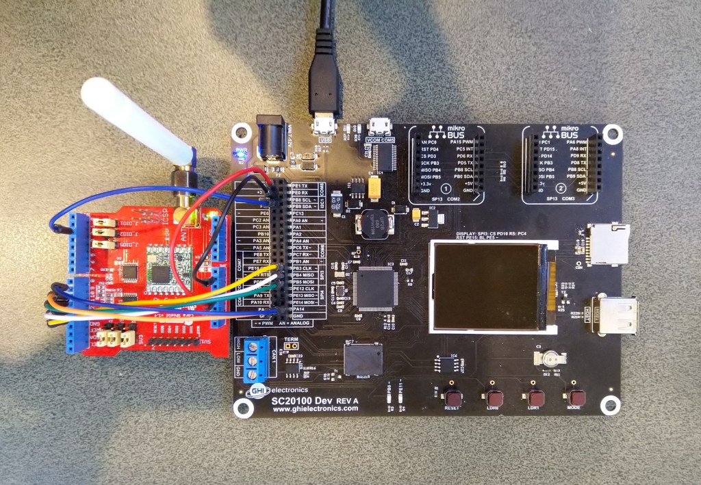
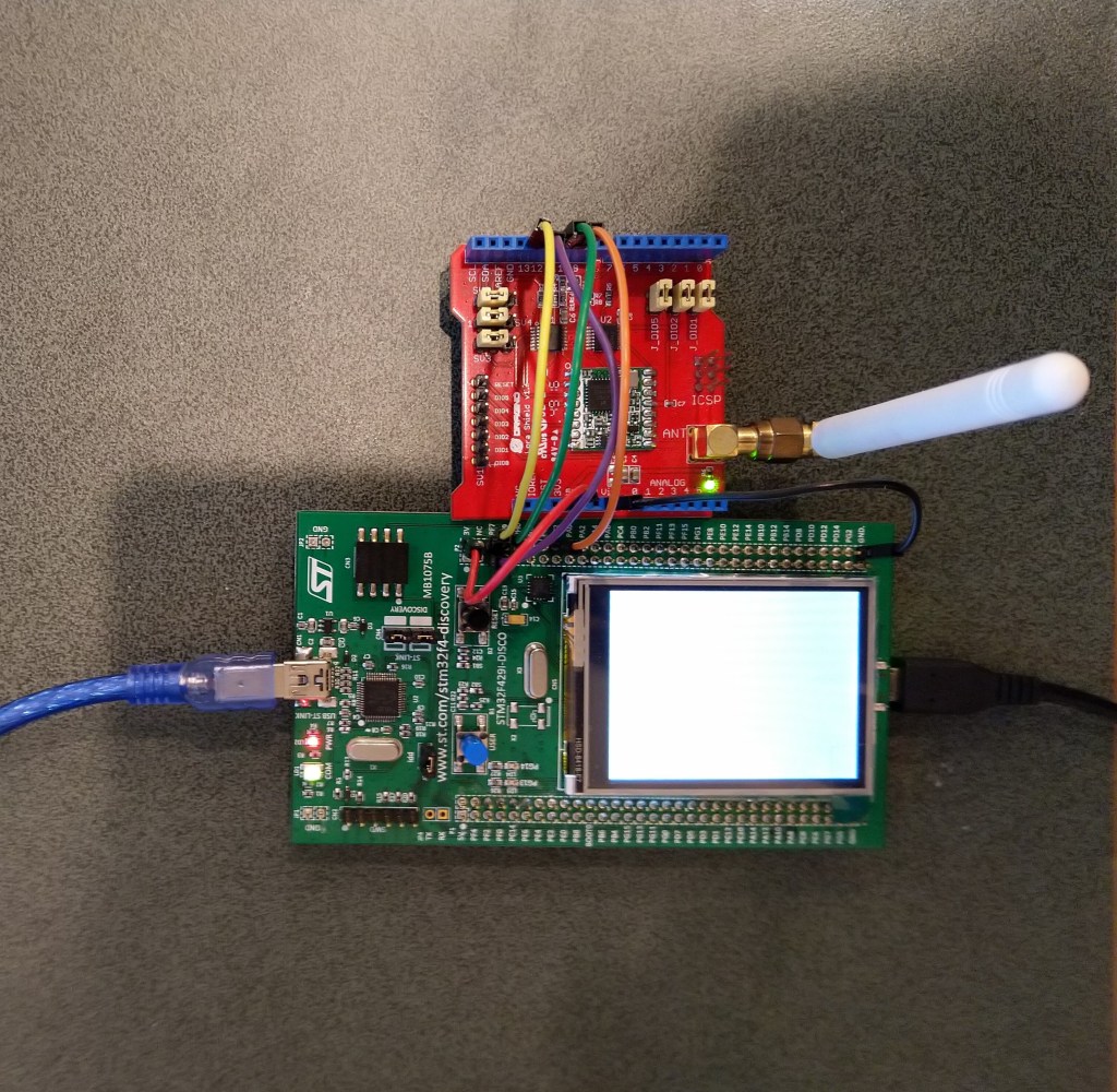
For testing this code I used the same version of the LoRaSetSyncWord example as Transmit Basic
class Program
{
#if ST_STM32F429I_DISCOVERY
private const string SpiBusId = "SPI5";
#endif
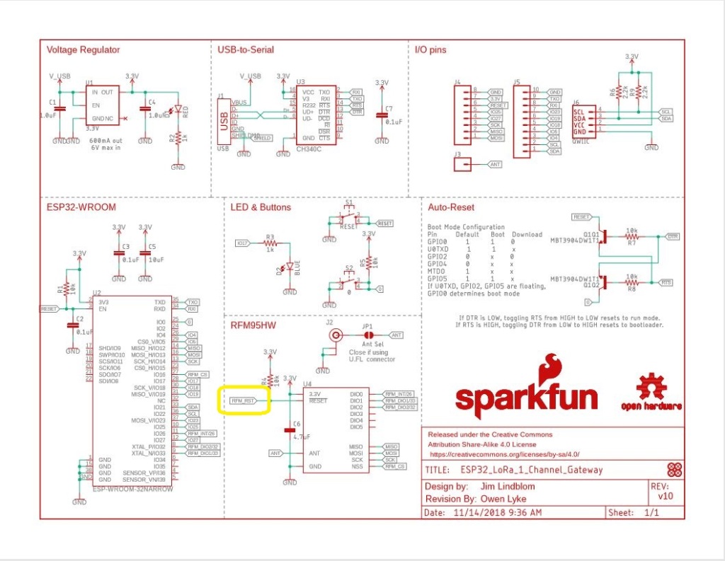
#if ESP32_WROOM_32_LORA_1_CHANNEL
private const string SpiBusId = "SPI1";
#endif
static void Main()
{
#if ST_STM32F429I_DISCOVERY
int chipSelectPinNumber = PinNumber('C', 2);
int resetPinNumber = PinNumber('C', 3);
#endif
#if ESP32_WROOM_32_LORA_1_CHANNEL
int chipSelectPinNumber = Gpio.IO16;
#endif
try
{
#if ESP32_WROOM_32_LORA_1_CHANNEL
Configuration.SetPinFunction(Gpio.IO12, DeviceFunction.SPI1_MISO);
Configuration.SetPinFunction(Gpio.IO13, DeviceFunction.SPI1_MOSI);
Configuration.SetPinFunction(Gpio.IO14, DeviceFunction.SPI1_CLOCK);
Rfm9XDevice rfm9XDevice = new Rfm9XDevice(SpiBusId, chipSelectPinNumber);
#endif
#if ST_STM32F429I_DISCOVERY
Rfm9XDevice rfm9XDevice = new Rfm9XDevice(SpiBusId, chipSelectPinNumber, resetPinNumber);
#endif
Thread.Sleep(500);
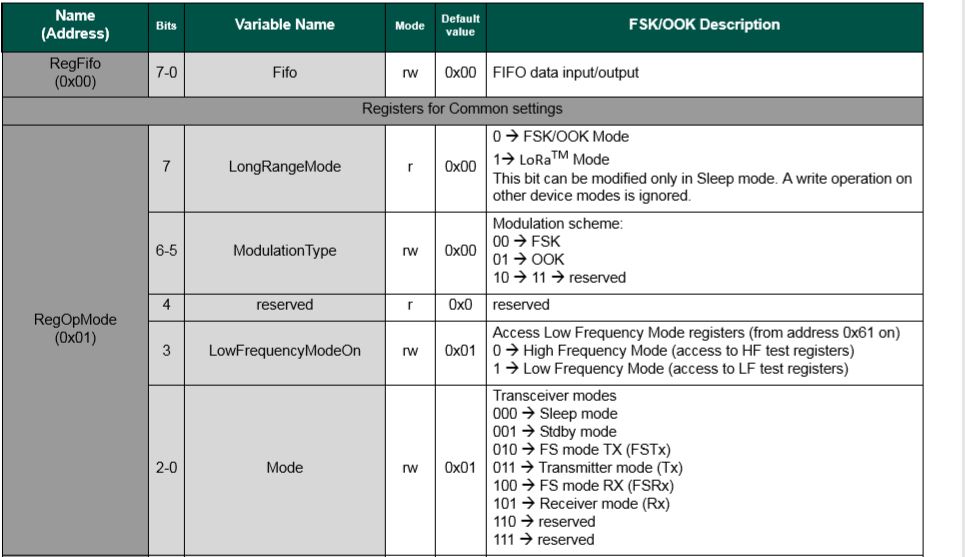
// Put device into LoRa + Sleep mode
rfm9XDevice.RegisterWriteByte(0x01, 0b10000000); // RegOpMode
// Set the frequency to 915MHz
byte[] frequencyWriteBytes = { 0xE4, 0xC0, 0x00 }; // RegFrMsb, RegFrMid, RegFrLsb
rfm9XDevice.RegisterWrite(0x06, frequencyWriteBytes);
rfm9XDevice.RegisterWriteByte(0x0F, 0x0); // RegFifoRxBaseAddress
rfm9XDevice.RegisterWriteByte(0x01, 0b10000101); // RegOpMode set LoRa & RxContinuous
while (true)
{
// Wait until a packet is received, no timeouts in PoC
Console.WriteLine("Receive-Wait");
byte irqFlags = rfm9XDevice.RegisterReadByte(0x12); // RegIrqFlags
while ((irqFlags & 0b01000000) == 0) // wait until RxDone cleared
{
Thread.Sleep(100);
irqFlags = rfm9XDevice.RegisterReadByte(0x12); // RegIrqFlags
Console.Write(".");
}
Console.WriteLine("");
Console.WriteLine($"RegIrqFlags 0X{irqFlags:X2}");
Console.WriteLine("Receive-Message");
byte currentFifoAddress = rfm9XDevice.RegisterReadByte(0x10); // RegFifiRxCurrent
rfm9XDevice.RegisterWriteByte(0x0d, currentFifoAddress); // RegFifoAddrPtr
byte numberOfBytes = rfm9XDevice.RegisterReadByte(0x13); // RegRxNbBytes
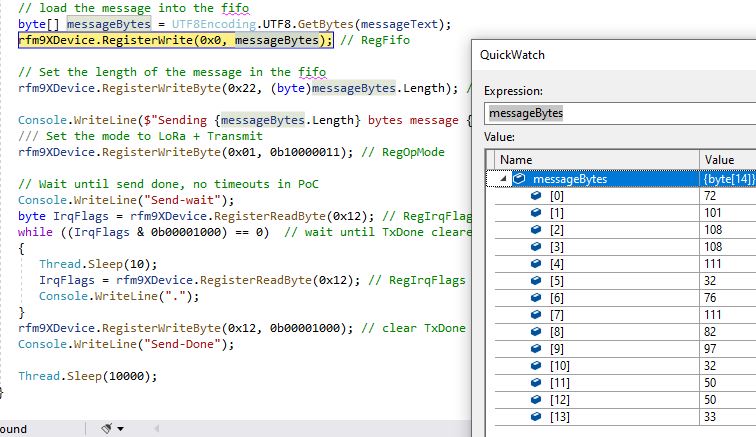
byte[] messageBytes = rfm9XDevice.RegisterRead(0x00, numberOfBytes); // RegFifo
rfm9XDevice.RegisterWriteByte(0x0d, 0);
rfm9XDevice.RegisterWriteByte(0x12, 0b11111111); // RegIrqFlags clear all the bits
// Remove unprintable characters from messages
for( int index = 0; index < messageBytes.Length; index++)
{
if ((messageBytes[index] < 0x20) || (messageBytes[index] > 0x7E))
{
messageBytes[index] = 0x20;
}
}
string messageText = UTF8Encoding.UTF8.GetString(messageBytes, 0, messageBytes.Length);
Console.WriteLine($"Received {messageBytes.Length} byte message {messageText}");
Console.WriteLine("Receive-Done");
}
}
catch (Exception ex)
{
Console.WriteLine(ex.Message);
}
}
#if ST_STM32F429I_DISCOVERY
static int PinNumber(char port, byte pin)
{
if (port < 'A' || port > 'J')
throw new ArgumentException();
return ((port - 'A') * 16) + pin;
}
#endif
}
The receive code works reliably but has no error detection or correction capability.
The thread '<No Name>' (0x2) has exited with code 0 (0x0).
Receive-Wait
................................................................
RegIrqFlags 0X50
Receive-Message
Received 17 byte message HeLoRa World! 114
Receive-Done
Receive-Wait
.......................................................................................................
RegIrqFlags 0X50
Receive-Message
Received 17 byte message HeLoRa World! 116
Receive-Done
Receive-Wait
.....................
RegIrqFlags 0X50
Receive-Message
Received 60 byte message  LoRaIoT1Maduino2at 50.2,ah 90,wsa 3,wsg 5,wd 178.50,r 0.00,
Receive-Done
Receive-Wait
.......................................................................................
RegIrqFlags 0X50
Receive-Message
Received 17 byte message HeLoRa World! 118
Receive-Done
Receive-Wait
I will look at implementing some sort of carrier-sense multiple access with collision avoidance solution to reduce the number of corrupted messages when two (or possibly more devices) transmit at the same time.