Windows 10 IoT Core triggered image upload to Azure Blob storage

Uploading the web camera images to Azure Storage was the next step.

PIR Sensor trigger

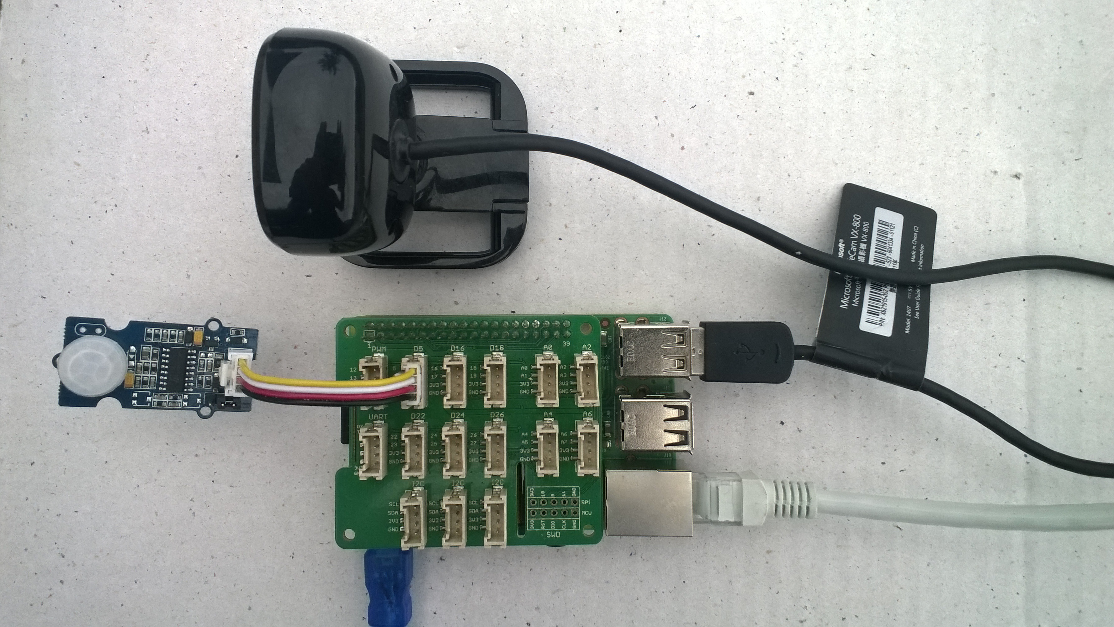
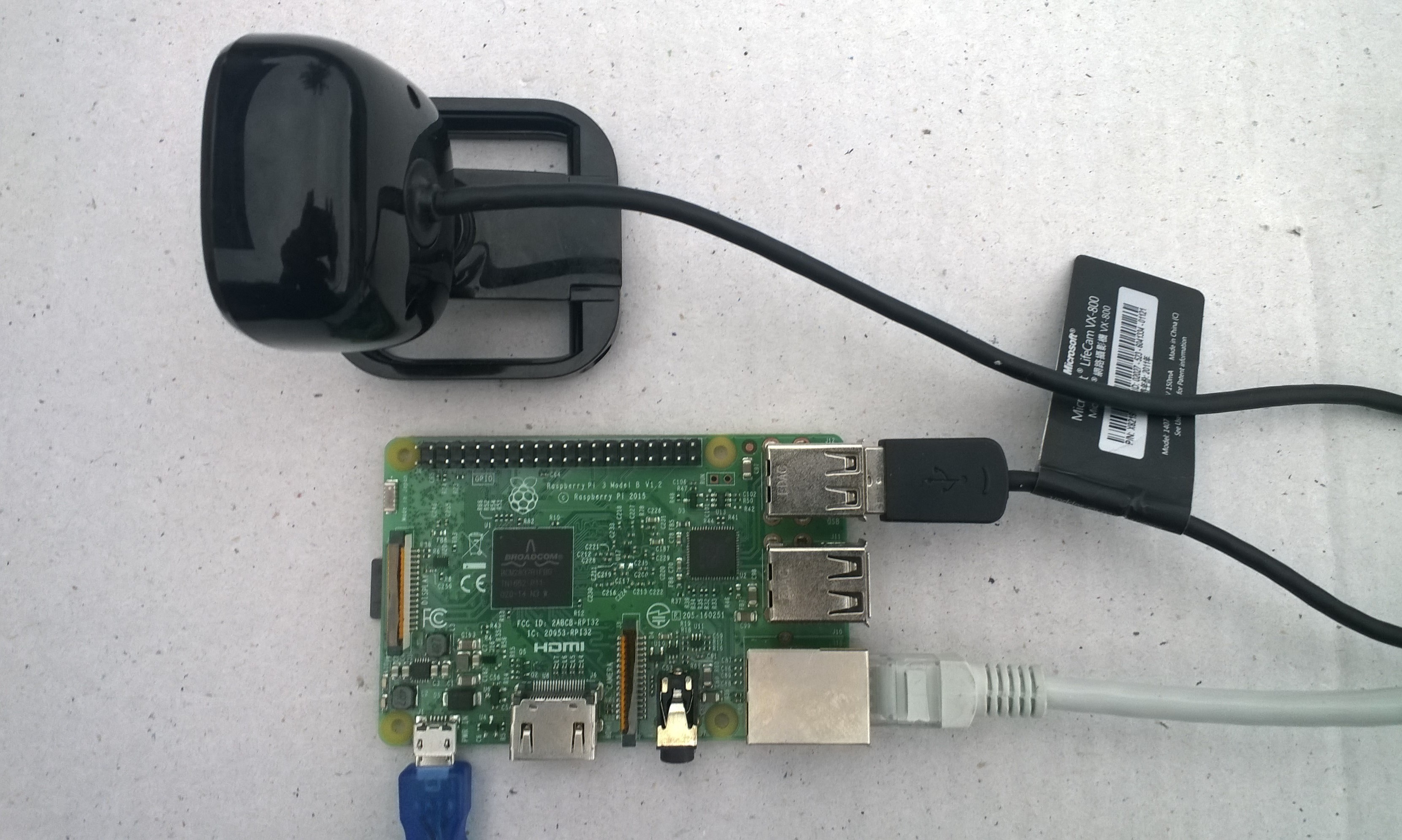
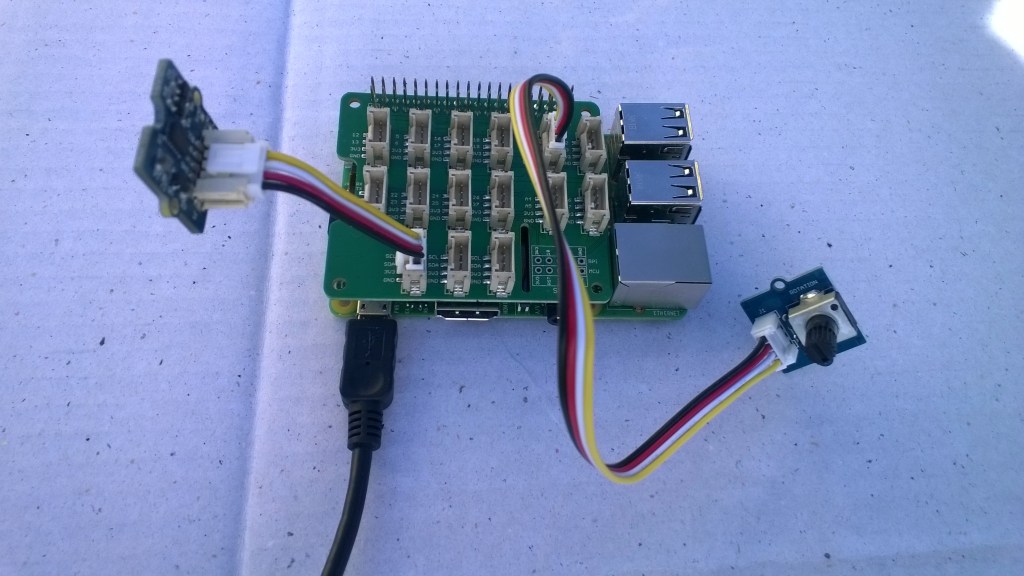
For my test harness (in addition to a RaspberryPI & generic USB Web camera) I’m using some Seeedstudio Grove devices

While working on this code I realised I had made some invalid assumptions about the stream and the image properties so I refactored the code (which also made it simpler).

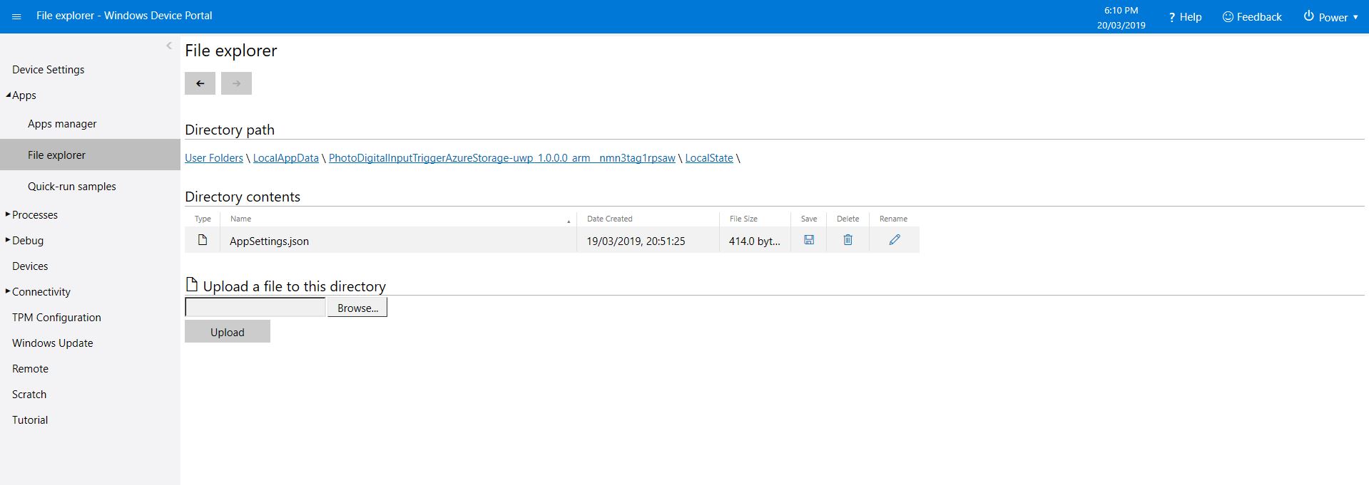
The Windows 10 IoT Core application has support for a JSON configuration file using Microsoft.Extensions.Configuration namespace functionality which took a bit of trial and error to get going.

IConfiguration configuration = new ConfigurationBuilder().
   AddJsonFile(localFolder.Path + @"\" + ConfigurationFilename, 
   false, 
   true).Build();

This gets the configuration subsystem to use the specified file in the application’s localstate folder. If there is no configuration file present i.e. the application has just been deployed for the first time or installed a template file is copied from the application install directory.

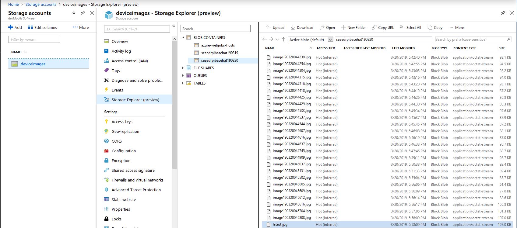
In the application configuration file you can specify the azure storage connection string, digital input port number, azure container name format (formatted machine name + Universal Coordinated Time(UTC)), the azure storage file name (formatted machine name + UTC) and the name of the file with the most recently uploaded image. These configuration settings are provided so that the image files can stored in “buckets” best suited to the way they are going to be processed.

{
  "AzureStorageConnectionString": "",
  "InterruptPinNumber": 5,
  "AzureContainerNameFormat": "{0}{1:yyMMdd}",
  "AzureImageFilenameFormat": "image{1:yyMMddHHmmss}.jpg",
  "AzureImageFilenameLatest": "latest.jpg"
} 

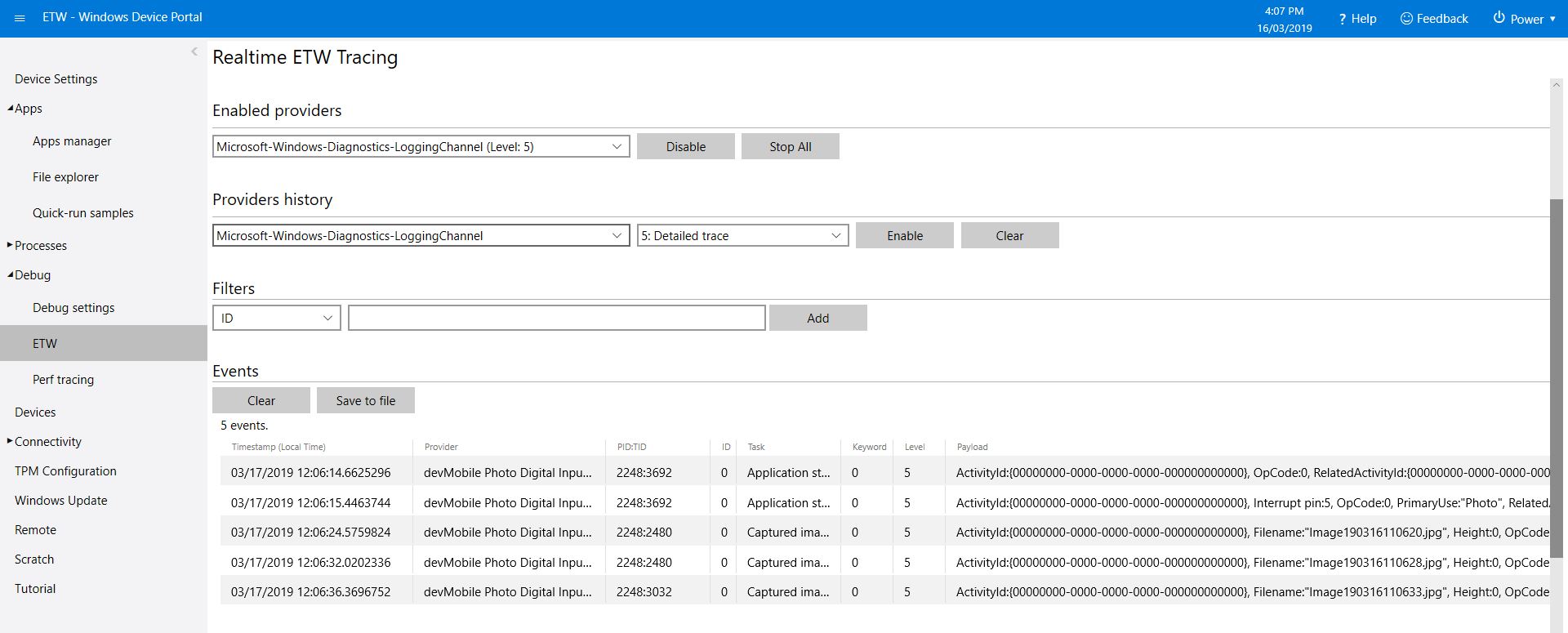
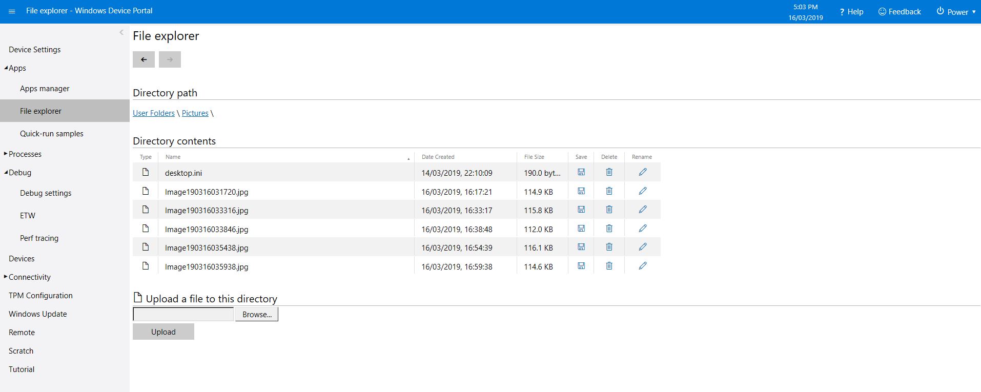
In my testing the pictures were stored in folders for each device/day and each image file had a timestamp in its name.

Azure Storage Explorer
/*
    Copyright ® 2019 March devMobile Software, All Rights Reserved
 
    MIT License
    ...
*/
namespace devMobile.Windows10IotCore.IoT.PhotoDigitalInputTriggerAzureStorage
{
	using System;
	using System.Diagnostics;

	using Microsoft.Extensions.Configuration;
	using Microsoft.WindowsAzure.Storage;
	using Microsoft.WindowsAzure.Storage.Blob;

	using Windows.ApplicationModel;
	using Windows.ApplicationModel.Background;
	using Windows.Devices.Gpio;
	using Windows.Foundation.Diagnostics;
	using Windows.Media.Capture;
	using Windows.Media.MediaProperties;
	using Windows.Storage;
	using Windows.System;

	public sealed class StartupTask : IBackgroundTask
	{
		private BackgroundTaskDeferral backgroundTaskDeferral = null;
		private readonly LoggingChannel logging = new LoggingChannel("devMobile Photo Digital Input Trigger Azure Storage demo", null, new Guid("4bd2826e-54a1-4ba9-bf63-92b73ea1ac4a"));
		private const string ConfigurationFilename = "appsettings.json";
		private GpioPin interruptGpioPin = null;
		private int interruptPinNumber;
		private MediaCapture mediaCapture;
		private string azureStorageConnectionString;
		private string azureStorageContainerNameFormat;
		private string azureStorageimageFilenameLatest;
		private string azureStorageImageFilenameFormat;
		private const string ImageFilenameLocal = "latest.jpg";
		private volatile bool cameraBusy = false;

		public void Run(IBackgroundTaskInstance taskInstance)
		{
			StorageFolder localFolder = ApplicationData.Current.LocalFolder;

			this.logging.LogEvent("Application starting");

			// Log the Application build, shield information etc.
			LoggingFields startupInformation = new LoggingFields();
			startupInformation.AddString("Timezone", TimeZoneSettings.CurrentTimeZoneDisplayName);
			startupInformation.AddString("OSVersion", Environment.OSVersion.VersionString);
			startupInformation.AddString("MachineName", Environment.MachineName);

			// This is from the application manifest 
			Package package = Package.Current;
			PackageId packageId = package.Id;
			PackageVersion version = packageId.Version;
			startupInformation.AddString("ApplicationVersion", string.Format($"{version.Major}.{version.Minor}.{version.Build}.{version.Revision}"));

			try
			{
				// see if the configuration file is present if not copy minimal sample one from application directory
				if (localFolder.TryGetItemAsync(ConfigurationFilename).AsTask().Result == null)
				{
					StorageFile templateConfigurationfile = Package.Current.InstalledLocation.GetFileAsync(ConfigurationFilename).AsTask().Result;
					templateConfigurationfile.CopyAsync(localFolder, ConfigurationFilename).AsTask();
					this.logging.LogMessage("JSON configuration file missing, templated created", LoggingLevel.Warning);
					return;
				}

				IConfiguration configuration = new ConfigurationBuilder().AddJsonFile(localFolder.Path + @"\" + ConfigurationFilename, false, true).Build();

				azureStorageConnectionString = configuration.GetSection("AzureStorageConnectionString").Value;
				startupInformation.AddString("AzureStorageConnectionString", azureStorageConnectionString);

				azureStorageContainerNameFormat = configuration.GetSection("AzureContainerNameFormat").Value;
				startupInformation.AddString("ContainerNameFormat", azureStorageContainerNameFormat);

				azureStorageImageFilenameFormat = configuration.GetSection("AzureImageFilenameFormat").Value;
				startupInformation.AddString("ImageFilenameFormat", azureStorageImageFilenameFormat);

				azureStorageimageFilenameLatest = configuration.GetSection("AzureImageFilenameLatest").Value;
				startupInformation.AddString("ImageFilenameLatest", azureStorageimageFilenameLatest);

				interruptPinNumber = int.Parse( configuration.GetSection("InterruptPinNumber").Value);
				startupInformation.AddInt32("Interrupt pin", interruptPinNumber);
			}
			catch (Exception ex)
			{
				this.logging.LogMessage("JSON configuration file load or settings retrieval failed " + ex.Message, LoggingLevel.Error);
				return;
			}

			try
			{
				mediaCapture = new MediaCapture();
				mediaCapture.InitializeAsync().AsTask().Wait();
			}
			catch (Exception ex)
			{
				this.logging.LogMessage("Camera configuration failed " + ex.Message, LoggingLevel.Error);
				return;
			}

			try
			{
				GpioController gpioController = GpioController.GetDefault();
				interruptGpioPin = gpioController.OpenPin(interruptPinNumber);
				interruptGpioPin.SetDriveMode(GpioPinDriveMode.InputPullUp);
				interruptGpioPin.ValueChanged += InterruptGpioPin_ValueChanged;
			}
			catch (Exception ex)
			{
				this.logging.LogMessage("Digital input configuration failed " + ex.Message, LoggingLevel.Error);
				return;
			}

			this.logging.LogEvent("Application started", startupInformation);

			//enable task to continue running in background
			backgroundTaskDeferral = taskInstance.GetDeferral();
		}

		private async void InterruptGpioPin_ValueChanged(GpioPin sender, GpioPinValueChangedEventArgs args)
		{
			DateTime currentTime = DateTime.UtcNow;
			Debug.WriteLine($"{DateTime.UtcNow.ToLongTimeString()} Digital Input Interrupt {sender.PinNumber} triggered {args.Edge}");

			if (args.Edge == GpioPinEdge.RisingEdge)
			{
				return;
			}

			// Just incase - stop code being called while photo already in progress
			if (cameraBusy)
			{
				return;
			}
			cameraBusy = true;

			try
			{
				StorageFile photoFile = await KnownFolders.PicturesLibrary.CreateFileAsync(ImageFilenameLocal, CreationCollisionOption.ReplaceExisting);
				ImageEncodingProperties imageProperties = ImageEncodingProperties.CreateJpeg();
				await mediaCapture.CapturePhotoToStorageFileAsync(imageProperties, photoFile);

				string azureContainername = string.Format(azureStorageContainerNameFormat, Environment.MachineName.ToLower(), currentTime);
				string azureStoragefilename = string.Format(azureStorageImageFilenameFormat, Environment.MachineName.ToLower(), currentTime);

				LoggingFields imageInformation = new LoggingFields();
				imageInformation.AddDateTime("TakenAtUTC", currentTime);
				imageInformation.AddString("LocalFilename", photoFile.Path);
				imageInformation.AddString("AzureContainerName", azureContainername);
				imageInformation.AddString("AzureStorageFilename", azureStoragefilename);
				imageInformation.AddString("AzureStorageFilenameLatest", azureStorageimageFilenameLatest);
				this.logging.LogEvent("Image saving to Azure storage", imageInformation);

				CloudStorageAccount storageAccount = CloudStorageAccount.Parse(azureStorageConnectionString);
				CloudBlobClient blobClient = storageAccount.CreateCloudBlobClient();

				CloudBlobContainer container = blobClient.GetContainerReference(azureContainername);
				await container.CreateIfNotExistsAsync();

				CloudBlockBlob blockBlob = container.GetBlockBlobReference(azureStoragefilename);
				await blockBlob.UploadFromFileAsync(photoFile);

				blockBlob = container.GetBlockBlobReference(azureStorageimageFilenameLatest);
				await blockBlob.UploadFromFileAsync(photoFile);

				this.logging.LogEvent("Image saved to Azure storage");
			}
			catch (Exception ex)
			{
				this.logging.LogMessage("Camera photo save or upload failed " + ex.Message, LoggingLevel.Error);
			}
			finally
			{
				cameraBusy = false;
			}
		}
	}
}

I need to add some code to ensure there is a minimum gap between photos and trial some different sensors. For example, an Adjustable Infrared Switch has proved to be a better option for some of my projects.

The code is available on GitHub and is a bit of a work in progress.

Windows 10 IoT Core image capture

Initiating image capture in response to a trigger was the next step, my plan is to use a button, or a proximity sensor like the passive infrared (PIR) module in the second image to trigger a photo.

Simple mechanical button trigger
PIR Sensor trigger

For my test rig (in addition to a RaspberryPI & generic USB Web camera) I’m using some Seeedstudio gear

The first step was to write an interrupt handler for the digital input, I figured triggering on the button push rather than release would make device more responsive.

/*
    Copyright ® 2019 Feb devMobile Software, All Rights Reserved
 
    MIT License
...
*/
namespace devMobile.Windows10IotCore.IoT.DigitalInputTrigger
{
	using System;
	using System.Diagnostics;
	using Windows.ApplicationModel.Background;
	using Windows.Devices.Gpio;

	public sealed class StartupTask : IBackgroundTask
	{
		private BackgroundTaskDeferral backgroundTaskDeferral = null;
		private GpioPin InterruptGpioPin = null;
		private const int InterruptPinNumber = 5;

		public void Run(IBackgroundTaskInstance taskInstance)
		{
			Debug.WriteLine("Application startup");

			try
			{
				GpioController gpioController = GpioController.GetDefault();

				InterruptGpioPin = gpioController.OpenPin(InterruptPinNumber);
				InterruptGpioPin.SetDriveMode(GpioPinDriveMode.InputPullUp);
				InterruptGpioPin.ValueChanged += InterruptGpioPin_ValueChanged;

				Debug.WriteLine("Digital Input Interrupt configuration success");
			}
			catch (Exception ex)
			{
				Debug.WriteLine($"Digital Input Interrupt configuration failed " + ex.Message);
				return;
			}

			//enable task to continue running in background
			backgroundTaskDeferral = taskInstance.GetDeferral();
		}

		private void InterruptGpioPin_ValueChanged(GpioPin sender, GpioPinValueChangedEventArgs args)
		{
			Debug.WriteLine($"{DateTime.UtcNow.ToLongTimeString()} Digital Input Interrupt {sender.PinNumber} triggered {args.Edge}");
		}
	}
}

Then I added in the camera functionality and made the interrupt handler async and await the camera and file system calls.

/*
    Copyright ® 2019 Feb devMobile Software, All Rights Reserved
 
    MIT License
...
*/
namespace devMobile.Windows10IotCore.IoT.PhotoDigitalInputTrigger
{
	using System;
	using System.Diagnostics;
	using Windows.ApplicationModel.Background;
	using Windows.Devices.Gpio;
	using Windows.Foundation.Diagnostics;
	using Windows.Media.Capture;
	using Windows.Media.MediaProperties;
	using Windows.Storage;

	public sealed class StartupTask : IBackgroundTask
	{
		private readonly LoggingChannel logging = new LoggingChannel("devMobile Photo Digital Input Trigger demo", null, new Guid("4bd2826e-54a1-4ba9-bf63-92b73ea1ac4a"));
		private BackgroundTaskDeferral backgroundTaskDeferral = null;
		private GpioPin InterruptGpioPin = null;
		private const int InterruptPinNumber = 5;
		private MediaCapture mediaCapture;
		private const string ImageFilenameFormat = "Image{0:yyMMddhhmmss}.jpg";
		private volatile bool CameraBusy = false;

		public void Run(IBackgroundTaskInstance taskInstance)
		{
			LoggingFields startupInformation = new LoggingFields();

			this.logging.LogEvent("Application starting");

			try
			{
				mediaCapture = new MediaCapture();
				mediaCapture.InitializeAsync().AsTask().Wait();
				Debug.WriteLine("Camera configuration success");

				GpioController gpioController = GpioController.GetDefault();

				InterruptGpioPin = gpioController.OpenPin(InterruptPinNumber);
				InterruptGpioPin.SetDriveMode(GpioPinDriveMode.InputPullUp);
				InterruptGpioPin.ValueChanged += InterruptGpioPin_ValueChanged;
				Debug.WriteLine("Digital Input Interrupt configuration success");
			}
			catch (Exception ex)
			{
				this.logging.LogMessage("Camera or digital input configuration failed " + ex.Message, LoggingLevel.Error);
				return;
			}

			startupInformation.AddString("PrimaryUse", mediaCapture.VideoDeviceController.PrimaryUse.ToString());
			startupInformation.AddInt32("Interrupt pin", InterruptPinNumber);

			this.logging.LogEvent("Application started", startupInformation);

			//enable task to continue running in background
			backgroundTaskDeferral = taskInstance.GetDeferral();
		}

		private async void InterruptGpioPin_ValueChanged(GpioPin sender, GpioPinValueChangedEventArgs args)
		{
			DateTime currentTime = DateTime.UtcNow;
			Debug.WriteLine($"{DateTime.UtcNow.ToLongTimeString()} Digital Input Interrupt {sender.PinNumber} triggered {args.Edge}");

			if (args.Edge == GpioPinEdge.RisingEdge)
			{
				return;
			}

			// Just incase - stop code being called while photo already in progress
			if (CameraBusy)
			{
				return;
			}
			CameraBusy = true;

			try
			{
				string filename = string.Format(ImageFilenameFormat, currentTime);

				IStorageFile photoFile = await KnownFolders.PicturesLibrary.CreateFileAsync(filename, CreationCollisionOption.ReplaceExisting);
				ImageEncodingProperties imageProperties = ImageEncodingProperties.CreateJpeg();
				await mediaCapture.CapturePhotoToStorageFileAsync(imageProperties, photoFile);

				LoggingFields imageInformation = new LoggingFields();

				imageInformation.AddDateTime("TakenAtUTC", currentTime);
				imageInformation.AddString("Filename", filename);
				imageInformation.AddString("Path", photoFile.Path);

				this.logging.LogEvent("Captured image saved to storage", imageInformation);
			}
			catch (Exception ex)
			{
				this.logging.LogMessage("Camera photo or save failed " + ex.Message, LoggingLevel.Error);
			}
			CameraBusy = false;
		}
	}
}

I found that contactor bounce was an issue (Grove- Touch Sensor OK) with larger mechanical buttons so I added the CameraBusy boolean flag to try and prevent re-entrancy problems. I’ll trial some other types of proximity and beam based on real-world student projects.

ETW logging or PIR triggered image capture

The code is available on GitHub and is a bit of a work in progress.

Windows 10 IoT Core image capture, upload and processing

One of my students wanted to do some image processing so to help her project along I am writing a series posts about capturing images on a Windows 10 IoT Core device. I’ll cover initiating the capturing of an image, uploading the image too Azure Blob storage, uploading the image to Azure blob storage associated with an Azure IoT Hub, then processing the images with the Azure Custom Vision Service.

USB Camera test rig

First step was to capture an image from a USB web camera and store it in the local file system.

/*
    Copyright ® 2019 Feb devMobile Software, All Rights Reserved

    MIT License
…
*/
namespace devMobile.Windows10IotCore.IoT.PhotoTimer
{
	using System;
	using System.Threading;
	using Windows.ApplicationModel.Background;
	using Windows.Foundation.Diagnostics;
	using Windows.Media.Capture;
	using Windows.Media.MediaProperties;
	using Windows.Storage;

	public sealed class StartupTask : IBackgroundTask
	{
		private readonly LoggingChannel logging = new LoggingChannel("devMobile Timer Photo demo", null, new Guid("4bd2826e-54a1-4ba9-bf63-92b73ea1ac4a"));
		private BackgroundTaskDeferral backgroundTaskDeferral = null;
		private Timer ImageUpdatetimer;
		private readonly TimeSpan ImageUpdateDueDefault = new TimeSpan(0, 0, 15);
		private readonly TimeSpan ImageUpdatePeriodDefault = new TimeSpan(0, 5, 0);
		private MediaCapture mediaCapture;
		private const string ImageFilenameFormat = "Image{0:yyMMddhhmmss}.jpg";

		public void Run(IBackgroundTaskInstance taskInstance)
		{
			LoggingFields startupInformation = new LoggingFields();

			this.logging.LogEvent("Application starting");

			try
			{
				mediaCapture = new MediaCapture();
				mediaCapture.InitializeAsync().AsTask().Wait();

				ImageUpdatetimer = new Timer(ImageUpdateTimerCallback, null, ImageUpdateDueDefault, ImageUpdatePeriodDefault);

			}
			catch (Exception ex)
			{
				this.logging.LogMessage("Camera configuration failed " + ex.Message, LoggingLevel.Error);
				return;
			}

			startupInformation.AddString("PrimaryUse", mediaCapture.VideoDeviceController.PrimaryUse.ToString());
			startupInformation.AddTimeSpan("Due", ImageUpdateDueDefault);
			startupInformation.AddTimeSpan("Period", ImageUpdatePeriodDefault);

			this.logging.LogEvent("Application started", startupInformation);

			//enable task to continue running in background
			backgroundTaskDeferral = taskInstance.GetDeferral();
		}

		private void ImageUpdateTimerCallback(object state)
		{
			DateTime currentTime = DateTime.UtcNow;

			try
			{
				string filename = string.Format(ImageFilenameFormat, currentTime);

				IStorageFile photoFile = KnownFolders.PicturesLibrary.CreateFileAsync(filename, CreationCollisionOption.ReplaceExisting).AsTask().Result;
				ImageEncodingProperties imageProperties = ImageEncodingProperties.CreateJpeg();
				mediaCapture.CapturePhotoToStorageFileAsync(imageProperties, photoFile).AsTask().Wait();

				LoggingFields imageInformation = new LoggingFields();
				imageInformation.AddDateTime("TakenAtUTC", currentTime);
				imageInformation.AddString("Filename", filename);
				imageInformation.AddString("Path", photoFile.Path);
				this.logging.LogEvent("Image saved to storage", imageInformation);
			}
			catch (Exception ex)
			{
				this.logging.LogMessage("Image capture or save to local storage failed " + ex.Message, LoggingLevel.Error);
			}
		}
	}
}

To get my camera to work I had to enable “pictures library”, “microphone” and “webcam” in the capabilities section of the application manifest.

As the application starts up and captures images it logs information to the Windows 10 IoT Core ETW logging

Windows 10 IoT Core Portal ETW Logging
Camera images in \user folders\pictures

The code is available on GitHub and is a bit of a work in progress.

RFM9X.IoTCore Adafruit LoRa Radio Bonnet support

The RFM9X chip select line on the Adafruit LoRa Radio Bonnet 868 or 915MHz with OLED RFM95W is connected to pin 26(CS1), the reset line to pin 22(GPIO25) and the interrupt line to pin 15(GPIO22).

When I ran the RFM9XLoRaDeviceClient from my RFM9X.IoTCore library with the following configuration

#if ADAFRUIT_RADIO_BONNET
	private const byte ResetLine = 25;
	private const byte InterruptLine = 22;
	private Rfm9XDevice rfm9XDevice = new Rfm9XDevice(ChipSelectPin.CS1, ResetLine, InterruptLine);
#endif

public void Run(IBackgroundTaskInstance taskInstance)
{
	rfm9XDevice.Initialise(Frequency, paBoost: true, rxPayloadCrcOn : true);
#if DEBUG
	rfm9XDevice.RegisterDump();
#endif
	rfm9XDevice.OnReceive += Rfm9XDevice_OnReceive;
#if ADDRESSED_MESSAGES_PAYLOAD
	rfm9XDevice.Receive(UTF8Encoding.UTF8.GetBytes(Environment.MachineName));
#else
	rfm9XDevice.Receive();
#endif
	rfm9XDevice.OnTransmit += Rfm9XDevice_OnTransmit;

	Task.Delay(10000).Wait();

	while (true)
	{
		string messageText = string.Format("Hello from {0} ! {1}", Environment.MachineName, MessageCount);
		MessageCount -= 1;

		byte[] messageBytes = UTF8Encoding.UTF8.GetBytes(messageText);
		Debug.WriteLine("{0:HH:mm:ss}-TX {1} byte message {2}", DateTime.Now, messageBytes.Length, messageText);
#if ADDRESSED_MESSAGES_PAYLOAD
		this.rfm9XDevice.Send(UTF8Encoding.UTF8.GetBytes("AddressHere"), messageBytes);
#else
		this.rfm9XDevice.Send(messageBytes);
#endif
		Task.Delay(10000).Wait();
	}
}
#endif

I could see messages being sent and received in the debug output

Register 0x3e - Value 0X00 - Bits 00000000
Register 0x3f - Value 0X00 - Bits 00000000
Register 0x40 - Value 0X00 - Bits 00000000
Register 0x41 - Value 0X00 - Bits 00000000
Register 0x42 - Value 0X12 - Bits 00010010
...
The thread 0xec4 has exited with code 0 (0x0).
The thread 0x868 has exited with code 0 (0x0).
22:21:47-RX PacketSnr 9.8 Packet RSSI -80dBm RSSI -122dBm = 59 byte message "�LoRaIoT1Maduino2at 62.8,ah 77,wsa 1,wsg 3,wd 34.88,r 0.00,"
22:21:52-TX 31 byte message Hello from AdaFruitIOLoRa ! 255
22:21:52-TX Done
The thread 0xbf8 has exited with code 0 (0x0).
The program '[3380] backgroundTaskHost.exe' has exited with code -1 (0xffffffff).

Next step modify my Adafruit IO and Azure IoT Hub/Central field gateways.

Windows 10 IoT Core Field Gateways “less is more”

After looking back at the technical support interactions for my Azure IoT Hubs Windows 10 IoT Core Field Gateway & AdaFruit.IO LoRa Windows 10 IoT Core Field Gateway I think removing a “feature” might make it easier for first time users.

In an early version of the software I used to provide a sample configuration JSON file in the associated GitHub repository. Users had to download this file to a computer, update it with their Azure IOT Hub or Azure IoT Central connection string or AdafruitIO APIKey , frequency and device address, then upload to the field gateway.

In a later version of the software I added code which created an empty configuration file with defaults for all settings, many of which were a distraction as the majority of users would never change them.

More settings meant there was more scope for users to change settings which broke the device samples and the gateway.

I have removed the code to generate the full configuration file (starting with Azure IOT Hub field gateway) and included a sample configuration file with the minimum required settings in the GitHub repositories and installers.

I am assuming that if a user wants to change advanced settings they can look at the code and/or documentation and figure out the setting names and valid values.

The new sample configuration file for a Azure IoT Hub telemetry only gateway is

{
  "AzureIoTHubDeviceConnectionString": "Azure IOT Hub connection string",
  "AzureIoTHubTransportType": "amqp",
  "SensorIDIsDeviceIDSensorID": false,
  "Address": "Device address",
  "Frequency": 915000000.0
}

The prebuilt installers available on GitHub post version 1.0.13.0 (Azure IoT Hub) and 1.0.5.0 (Adafruit.IO) will implement this model.

Grove Base Hat for Raspberry PI Windows 10 IoT Core

After some experimentation I have a proof of concept Windows 10 IoT Core library for accessing the Analog to Digital Convertor (ADC) on a Grove Base Hat for Raspberry PI.

I can read the raw, voltage & % values just fine but the Version number isn’t quite what I expected. In the python sample code I can see the register numbers etc.

def __init__(self, address=0x04):
self.address = address
self.bus = grove.i2c.Bus()

def read_raw(self, channel):
addr = 0x10 + channel
return self.read_register(addr)

# read input voltage (mV)
def read_voltage(self, channel):
addr = 0x20 + channel
return self.read_register(addr)

# input voltage / output voltage (%)
def read(self, channel):
addr = 0x30 + channel
return self.read_register(addr)

@property
def name(self):
id = self.read_register(0x0)
if id == RPI_HAT_PID:
return RPI_HAT_NAME
elif id == RPI_ZERO_HAT_PID:
return RPI_ZERO_HAT_NAME

@property
def version(self):
return self.read_register(0x3)

When I read register 0x3 to get the version info the value changes randomly. Format = register num, byte value, word value

0,4,4 1,134,10374 2,2,2 3,82,79 4,0,0 5,0,0 6,0,0 7,0,0 8,0,0 9,0,0 10,0,0 11,0,0 12,0,0 13,0,0 14,0,0 15,0,0 
0,4,4 1,134,10374 2,2,2 3,86,69 4,0,0 5,0,0 6,0,0 7,0,0 8,0,0 9,0,0 10,0,0 11,0,0 12,0,0 13,0,0 14,0,0 15,0,0 
0,4,4 1,134,10374 2,2,2 3,32,66 4,0,0 5,0,0 6,0,0 7,0,0 8,0,0 9,0,0 10,0,0 11,0,0 12,0,0 13,0,0 14,0,0 15,0,0 

It looks like register 1 or 2 (134/10374 or 2/2) might contain the device version information.

The code is available on GitHub here. Next time I purchase some gear from Seeedstudio I’ll include a Grove Base Hat For Raspberry PI Zero and extend the software so they work as well.

public sealed class StartupTask : IBackgroundTask
{
   private ThreadPoolTimer timer;
   private BackgroundTaskDeferral deferral;
   AnalogPorts analogPorts = new AnalogPorts();

   public void Run(IBackgroundTaskInstance taskInstance)
   {
      deferral = taskInstance.GetDeferral();

      analogPorts.Initialise();

      byte version = analogPorts.Version();
      Debug.WriteLine($"Version {version}");

      double powerSupplyVoltage = analogPorts.PowerSupplyVoltage();
      Debug.WriteLine($"Power supply voltage {powerSupplyVoltage}v");

      timer = ThreadPoolTimer.CreatePeriodicTimer(AnalogPorts, TimeSpan.FromSeconds(5));
   }

   void AnalogPorts(ThreadPoolTimer timer)
   {
      try
      {
         ushort valueRaw;
         valueRaw = analogPorts.ReadRaw(AnalogPorts.AnalogPort.A0);
         Debug.WriteLine($"A0 Raw {valueRaw}");

         double valueVoltage;
         valueVoltage = analogPorts.ReadVoltage(AnalogPorts.AnalogPort.A0);
         Debug.WriteLine($"A0 {valueVoltage}v");

         double value;
         value = analogPorts.Read(AnalogPorts.AnalogPort.A0);
         Debug.WriteLine($"A0 {value}");
      }
      catch (Exception ex)
      {
         Debug.WriteLine($"AnalogPorts Read failed {ex.Message}");
      }
   }
}

Grove Base Hat for Raspberry PI Investigation

For a couple of projects I had been using the Dexter industries GrovePI+ and the Grove Base Hat for Raspberry PI looked like a cheaper alternative for many applications, but it lacked Windows 10 IoT Core support.

My first project was to build a Inter Integrated Circuit(I2C) device scanner to check that the Grove Base Hat STM32 MCU I2C client implementation on a “played nice” with Windows 10 IoT core.

My Visual Studio 2017 project (I2C Device Scanner) scans all the valid 7bit I2C addresses and in the debug output displayed the two “found” devices, a Grove- 3 Axis Accelerometer(+-16G) (ADXL345) and the Grove Base Hat for Raspberry PI.

backgroundTaskHost.exe' (CoreCLR: CoreCLR_UWP_Domain): Loaded 'C:\Data\Users\DefaultAccount\AppData\Local\DevelopmentFiles\I2CDeviceScanner-uwpVS.Debug_ARM.Bryn.Lewis\System.Diagnostics.Debug.dll'. Skipped loading symbols. Module is optimized and the debugger option 'Just My Code' is enabled.

'backgroundTaskHost.exe' (CoreCLR: CoreCLR_UWP_Domain): Loaded 'C:\Data\Users\DefaultAccount\AppData\Local\DevelopmentFiles\I2CDeviceScanner-uwpVS.Debug_ARM.Bryn.Lewis\System.Linq.dll'. Skipped loading symbols. Module is optimized and the debugger option 'Just My Code' is enabled.
Exception thrown: 'System.IO.FileNotFoundException' in devMobile.Windows10IoTCore.I2CDeviceScanner.winmd
WinRT information: Slave address was not acknowledged.
.......
Exception thrown: 'System.IO.FileNotFoundException' in devMobile.Windows10IoTCore.I2CDeviceScanner.winmd
WinRT information: Slave address was not acknowledged.

I2C Controller \\?\ACPI#MSFT8000#1#{a11ee3c6-8421-4202-a3e7-b91ff90188e4}\I2C1 has 2 devices
Address 0x4
Address 0x53
Raspberry PI with Grove Base Hat & ADXL345 & Rotary angle sensor
Raspberry PI with Grove Base Hat I2C test rig

The next step was to confirm I could read the device ID of the ADXL345 and the Grove Base Hat for RaspberryPI. I had to figure out the Grove Base Hat for RaspberryPI from the Seeedstudio Python code.

I2CDevicePinger ADXL345 Debug output

...
'backgroundTaskHost.exe' (CoreCLR: CoreCLR_UWP_Domain): Loaded 'C:\Data\Users\DefaultAccount\AppData\Local\DevelopmentFiles\I2CDevicePinger-uwpVS.Debug_ARM.Bryn.Lewis\System.Diagnostics.Debug.dll'. Skipped loading symbols. Module is optimized and the debugger option 'Just My Code' is enabled.
DeviceID 0XE5

The DeviceID for the ADXL345 matched the DEVID in the device datasheet.

I2CDevicePinger Debug output

'backgroundTaskHost.exe' (CoreCLR: CoreCLR_UWP_Domain): Loaded 'C:\Data\Users\DefaultAccount\AppData\Local\DevelopmentFiles\I2CDevicePinger-uwpVS.Debug_ARM.Bryn.Lewis\System.Diagnostics.Debug.dll'. Skipped loading symbols. Module is optimized and the debugger option 'Just My Code' is enabled.
DeviceID 0X4

The DeviceID for the Grove Base Hat for RaspberryPI matched

RPI_HAT_PID = 0x0004 in the Python code.

The last test application reads the raw value of the specified analog input

public async void Run(IBackgroundTaskInstance taskInstance)
{
   string aqs = I2cDevice.GetDeviceSelector();
   DeviceInformationCollection I2CBusControllers = await DeviceInformation.FindAllAsync(aqs);

   if (I2CBusControllers.Count != 1)
   {
      Debug.WriteLine("Unexpect number of I2C bus controllers found");
      return;
   }

   I2cConnectionSettings settings = new I2cConnectionSettings(0x04)
   {
      BusSpeed = I2cBusSpeed.StandardMode,
      SharingMode = I2cSharingMode.Shared,
   };

   using (I2cDevice device = I2cDevice.FromIdAsync(I2CBusControllers[0].Id, settings).AsTask().GetAwaiter().GetResult())
   {
      try
      {
         ushort value = 0;
         // From the Seeedstudio python
	 // 0x10 ~ 0x17: ADC raw data
	 // 0x20 ~ 0x27: input voltage
         // 0x29: output voltage (Grove power supply voltage)
         // 0x30 ~ 0x37: input voltage / output voltage						
         do
	 {
            byte[] writeBuffer = new byte[1] { 0x10 };
            byte[] readBuffer = new byte[2] { 0, 0 };

            device.WriteRead(writeBuffer, readBuffer);
            value = BitConverter.ToUInt16(readBuffer, 0);

            Debug.WriteLine($"Value {value}");

            Task.Delay(1000).GetAwaiter().GetResult();
         }
         while (value != 0);
      }
      Catch (Exception ex)
      {
         Debug.WriteLine(ex.Message);
      }
   }
}

GroveBaseHatRPIRegisterReader Debug output

'backgroundTaskHost.exe' (CoreCLR: CoreCLR_UWP_Domain): Loaded 'C:\Data\Users\DefaultAccount\AppData\Local\DevelopmentFiles\GroveBaseHatRPIRegisterReader-uwpVS.Debug_ARM.Bryn.Lewis\System.Diagnostics.Debug.dll'. Skipped loading symbols. Module is optimized and the debugger option 'Just My Code' is enabled.
Value 3685
Value 3685
Value 3688
Value 3681
Value 3681
Value 3688
Value 3688
Value 3683

The output changed when I adjusted the rotary angle sensor (0-4095) which confirmed I could reliably read the Analog input values.

The code for my test harness applications is available on github, the next step is to build a library for the Grove Base Hat for RaspberryPI

RFM9X.IoTCore Payload Addressing

The reason for RFM9XLoRaNet was so that I could build a field gateway to upload telemetry data from “cheap n cheerful” *duino devices to Azure IoT Hubs and AdaFruit.IO.

I have extended the Windows10IoTCore sample application and library to show how the conditional compilation directive ADDRESSED_MESSAGES_PAYLOAD controls the configuration.

When the application is started the RFM9X is in sleep mode, then when the Receive method is called the device is set to ReceiveContinuous.

public void Run(IBackgroundTaskInstance taskInstance)
{
   rfm9XDevice.Initialise(915000000.0, paBoost: true, rxPayloadCrcOn : true);

#if DEBUG
   rfm9XDevice.RegisterDump();
#endif

#if ADDRESSED_MESSAGES_PAYLOAD
   rfm9XDevice.OnReceive += Rfm9XDevice_OnReceive;
   rfm9XDevice.Receive(UTF8Encoding.UTF8.GetBytes(Environment.MachineName));
#else
   rfm9XDevice.Receive();
#endif
   rfm9XDevice.OnTransmit += Rfm9XDevice_OnTransmit;

   Task.Delay(10000).Wait();

   while (true)
   {
      string messageText = string.Format("Hello from {0} ! {1}", Environment.MachineName, NessageCount);
      MessageCount -= 1;

      byte[] messageBytes = UTF8Encoding.UTF8.GetBytes(messageText);
      Debug.WriteLine("{0:HH:mm:ss}-TX {1} byte message {2}", DateTime.Now, messageBytes.Length, messageText);
#if ADDRESSED_MESSAGES_PAYLOAD
      this.rfm9XDevice.Send(UTF8Encoding.UTF8.GetBytes("AddressGoesHere"), messageBytes);
#else
      this.rfm9XDevice.Send(messageBytes);
#endif
      Task.Delay(10000).Wait();
   }
}

On receipt of a message, the message is parsed and the to/from addresses and payload extracted (ADDRESSED_MESSAGES defined) or passed to the client application for processing.

private void Rfm9XDevice_OnReceive(object sender, Rfm9XDevice.OnDataReceivedEventArgs e)
{
   try
   {
      string messageText = UTF8Encoding.UTF8.GetString(e.Data);

#if ADDRESSED_MESSAGES_PAYLOAD
      string addressText = UTF8Encoding.UTF8.GetString(e.Address);

      Debug.WriteLine(@"{0:HH:mm:ss}-RX From {1} PacketSnr {2:0.0} Packet RSSI {3}dBm RSSI {4}dBm = {5} byte message ""{6}""", DateTime.Now, addressText, e.PacketSnr, e.PacketRssi, e.Rssi, e.Data.Length, messageText);
#else
      Debug.WriteLine(@"{0:HH:mm:ss}-RX PacketSnr {1:0.0} Packet RSSI {2}dBm RSSI {3}dBm = {4} byte message ""{5}""", DateTime.Now, e.PacketSnr, e.PacketRssi, e.Rssi, e.Data.Length, messageText);
#endif
   }
   catch (Exception ex)
   {
      Debug.WriteLine(ex.Message);
   }
}

The addressing implementation needs further testing and I’m building sample .NetMF and *duino clients.

Rfm9xLoRaDevice LNA gain revisited

While fixing up the Signal to Noise Ratio(SNR) and Received Signal Strength Indication(RSSI) in a previous post I noted the Low Noise Amplifier(LNA) had High Frequency(LF) and Low Frequency settings.

First step was to update the initialise method parameter list (the parameter list is huge but for most values the defaults are fine)

		public void Initialise(RegOpModeMode modeAfterInitialise, // RegOpMode
			double frequency = FrequencyDefault, // RegFrMsb, RegFrMid, RegFrLsb
			bool rxDoneignoreIfCrcMissing = true, bool rxDoneignoreIfCrcInvalid = true,
			bool paBoost = false, byte maxPower = RegPAConfigMaxPowerDefault, byte outputPower = RegPAConfigOutputPowerDefault, // RegPaConfig
			bool ocpOn = true, byte ocpTrim = RegOcpOcpTrimDefault, // RegOcp
			RegLnaLnaGain lnaGain = LnaGainDefault, bool lnaBoostLF = false, bool lnaBoostHf = false, // RegLna
			RegModemConfigBandwidth bandwidth = RegModemConfigBandwidthDefault, RegModemConfigCodingRate codingRate = RegModemConfigCodingRateDefault, RegModemConfigImplicitHeaderModeOn implicitHeaderModeOn = RegModemConfigImplicitHeaderModeOnDefault, //RegModemConfig1
			RegModemConfig2SpreadingFactor spreadingFactor = RegModemConfig2SpreadingFactorDefault, bool txContinuousMode = false, bool rxPayloadCrcOn = false,
			ushort symbolTimeout = SymbolTimeoutDefault,
			ushort preambleLength = PreambleLengthDefault,
			byte payloadLength = PayloadLengthDefault,
			byte payloadMaxLength = PayloadMaxLengthDefault,
			byte freqHoppingPeriod = FreqHoppingPeriodDefault,
			bool lowDataRateOptimize = false, bool agcAutoOn = false,
			byte ppmCorrection = ppmCorrectionDefault,
			RegDetectOptimizeDectionOptimize detectionOptimize = RegDetectOptimizeDectionOptimizeDefault,
			bool invertIQ = false,
			RegisterDetectionThreshold detectionThreshold = RegisterDetectionThresholdDefault,
			byte syncWord = RegSyncWordDefault)
		{

which became

public void Initialise(RegOpModeMode modeAfterInitialise, // RegOpMode
	double frequency = FrequencyDefault, // RegFrMsb, RegFrMid, RegFrLsb
	bool rxDoneignoreIfCrcMissing = true, bool rxDoneignoreIfCrcInvalid = true,
	bool paBoost = false, byte maxPower = RegPAConfigMaxPowerDefault, byte outputPower = RegPAConfigOutputPowerDefault, // RegPaConfig
	bool ocpOn = true, byte ocpTrim = RegOcpOcpTrimDefault, // RegOcp
	RegLnaLnaGain lnaGain = LnaGainDefault, bool lnaBoost = false, // RegLna
	RegModemConfigBandwidth bandwidth = RegModemConfigBandwidthDefault, RegModemConfigCodingRate codingRate = RegModemConfigCodingRateDefault, RegModemConfigImplicitHeaderModeOn implicitHeaderModeOn = RegModemConfigImplicitHeaderModeOnDefault, //RegModemConfig1
	RegModemConfig2SpreadingFactor spreadingFactor = RegModemConfig2SpreadingFactorDefault, bool txContinuousMode = false, bool rxPayloadCrcOn = false,
	ushort symbolTimeout = SymbolTimeoutDefault,
	ushort preambleLength = PreambleLengthDefault,
	byte payloadLength = PayloadLengthDefault,
	byte payloadMaxLength = PayloadMaxLengthDefault,
	byte freqHoppingPeriod = FreqHoppingPeriodDefault,
	bool lowDataRateOptimize = false, bool agcAutoOn = false,
	byte ppmCorrection = ppmCorrectionDefault,
	RegDetectOptimizeDectionOptimize detectionOptimize = RegDetectOptimizeDectionOptimizeDefault,
	bool invertIQ = false,
	RegisterDetectionThreshold detectionThreshold = RegisterDetectionThresholdDefault,
	byte syncWord = RegSyncWordDefault)
{

Then in the code for configuring the RegLna the frequency band is checked

		// Set RegLna if any of the settings not defaults
			if ((lnaGain != LnaGainDefault) || (lnaBoost != false))
			{
				byte regLnaValue = (byte)lnaGain;
				if (lnaBoost)
				{
					if (Frequency > RFMidBandThreshold)
					{
						regLnaValue |= RegLnaLnaBoostHfOn;
					}
					else
					{
						regLnaValue |= RegLnaLnaBoostLfOn;
					}
				}
				RegisterManager.WriteByte((byte)Registers.RegLna, regLnaValue);
			}

The HF & LF differences where not obviously handled in Arduino-LoRa library and the Semtech LoRaMac node GitHub repository wasn’t so helpful this time.

Not so confident with these changes need to test with my 434MHz devices

Rfm9xLoRaDevice SNR and RSSI revisited

The magic numbers for the high frequency(HF) vs. low frequency(LF) adjustment bugged me

int rssi = this.RegisterManager.ReadByte((byte)Registers.RegRssiValue);
if (Frequency < 868E6)
	rssi = -164 + rssi; // LF output port
else
	rssi = -157 + rssi; // HF output port

int packetRssi = this.RegisterManager.ReadByte((byte)Registers.RegPktRssiValue);
if (Frequency < 868E6)
	packetRssi = -164 + rssi; // LF output port
else
	packetRssi = -157 + rssi; // HF output port

After some searching I ended up at the Semetch LoRaMac node github repository. In that code they had a number of constants which looked like a better approach.

if( SX1276.Settings.Channel > RF_MID_BAND_THRESH )
{
   rssi = RSSI_OFFSET_HF + SX1276Read( REG_LR_RSSIVALUE );
}
else
{
   rssi = RSSI_OFFSET_LF + SX1276Read( REG_LR_RSSIVALUE );
}

I also fixed a couple of bugs I noticed with the maths and the code now looks like this

int rssi = this.RegisterManager.ReadByte((byte)Registers.RegRssiValue);
if (Frequency > RFMidBandThreshold)
   rssi = RssiAdjustmentHF + rssi;
else
   rssi = RssiAdjustmentLF + rssi;

int packetRssi = this.RegisterManager.ReadByte((byte)Registers.RegPktRssiValue);
if (Frequency > RFMidBandThreshold)
   packetRssi = RssiAdjustmentHF + packetRssi;
else
   packetRssi = RssiAdjustmentLF + packetRssi;

This has also got me thing about how RegLna – LnaBoostLf/LnaBoostHf should be handled as well.