Random wanderings through Microsoft Azure esp. PaaS plumbing, the IoT bits, AI on Micro controllers, AI on Edge Devices, .NET nanoFramework, .NET Core on *nix and ML.NET+ONNX
While doing some stress testing I noticed an odd message go past in the Visual Studio output window. I had multiple devices sending addressed messages (both individual and broadcast) to the Adafruit RFM69 HCW Radio Bonnet, on my Windows 10 IoT Core device while it was sending a message every 5 seconds.
Received From 153 a 13 byte message Hello World:7
18:43:56.544 RegIrqFlags2 01100110
18:43:56.558 RegIrqFlags1 11011001
18:43:56.575 Address 0X66 01100110
Received From 102 a 15 byte message Hello World:162
The thread 0x254 has exited with code 0 (0x0).
18:43:57.699 Send-hello world 6:43:57 PM
18:43:57.699 RegIrqFlags2 01100110
18:43:57.731 RegIrqFlags1 10000000
18:43:57.747 Address 0X66 01100110
18:43:57.765 Send-Done
Received From 102 a 15 byte message Hello Woooooooo
18:43:57.987 RegIrqFlags2 00001000
18:43:58.003 RegIrqFlags1 10110000
18:43:58.017 Transmit-Done
Transmit-Done
18:43:58.825 RegIrqFlags2 01100110
18:43:58.838 RegIrqFlags1 11011001
18:43:58.857 Address 0X66 01100110
Received From 102 a 15 byte message Hello World:164
18:43:59.966 RegIrqFlags2 01100110
18:43:59.979 RegIrqFlags1 11011001
18:43:59.998 Address 0X66 01100110
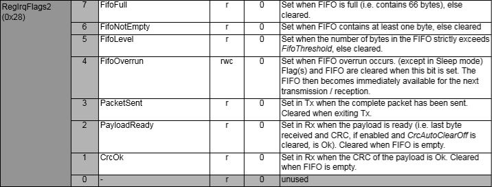
The odd thing was that the RegIrqFlags2 CrcOk (bit 1) was set but the message was still corrupt.
RegIrqFlags2 bit flags from SX1231 datasheet
After looking at the code I think the problem was the reading of the received message bytes from the device FIFO and the writing of bytes of message to be transmitted into the device FIFO overlapped. To stop this occurring again I have added code to synchronise access (using a Lock) to the FIFO.
private readonly Object Rfm9XRegFifoLock = new object();
...
private void ProcessPayloadReady(RegIrqFlags1 irqFlags1, RegIrqFlags2 irqFlags2)
{
	byte? address = null;
	byte numberOfBytes;
	byte[] messageBytes;

	lock (Rfm9XRegFifoLock)
	{
		// Read the length of the buffer if variable length packets
		if (PacketFormat == RegPacketConfig1PacketFormat.VariableLength)
		{
			numberOfBytes = RegisterManager.ReadByte((byte)Rfm69HcwDevice.Registers.RegFifo);
		}
		else
		{
			numberOfBytes = PayloadLength;
		}

		// Remove the address from start of the payload
		if (AddressingEnabled)
		{
			address = RegisterManager.ReadByte((byte)Rfm69HcwDevice.Registers.RegFifo);

			Debug.WriteLine("{0:HH:mm:ss.fff} Address 0X{1:X2} {2}", DateTime.Now, address, Convert.ToString((byte)address, 2).PadLeft(8, '0'));
			numberOfBytes--;
		}

		// Allocate a buffer for the payload and read characters from the Fifo
		messageBytes = new byte[numberOfBytes];

		for (int i = 0; i < numberOfBytes; i++)
		{
			messageBytes[i] = RegisterManager.ReadByte((byte)Rfm69HcwDevice.Registers.RegFifo);
		}
	}
...
public void SendMessage(byte[] messageBytes)
{
#region Guard conditions
#endregion

	lock (Rfm9XRegFifoLock)
	{
		SetMode(RegOpModeMode.StandBy);

		if (PacketFormat == RegPacketConfig1PacketFormat.VariableLength)
		{
			RegisterManager.WriteByte((byte)Registers.RegFifo, (byte)messageBytes.Length);
		}

		foreach (byte b in messageBytes)
		{
			this.RegisterManager.WriteByte((byte)Registers.RegFifo, b);
		}

		SetMode(RegOpModeMode.Transmit);
	}
}
The code has been running for a day without any corrupted messages so the lock appears to be working. I can most probably reduce the duration which I hold the lock for but that will require some more stress testing.
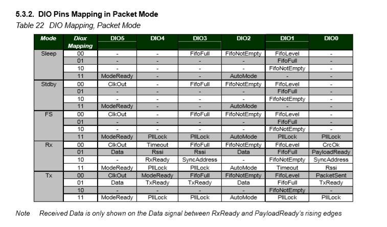
The RFM69CW/RFM69HCW module (based on the Semtech SX1231/SX1231H) has configurable digital outputs (RegDIOMapping1 & RegDIOMapping2) . Which I use to trigger interrupts on my Windows 10 IoT Core or Arduino devices. Currently (Sep 2019) the library only supports the mapping of the digital outputs D0 & D1 when the RFM69 is in Packet Mode.
RegiDIOMapping0 & RegDIOMapping2 settings for DIO thru DIO5
I added some additional constants and enumerations for the other settings configured in RegDioMapping1 & RegDioMapping2.
I had several failed attempts at defining suitable enumerations for configuring the RegDioMapping1 & RegDioMapping2 registers. I initially started with an enumeration for each Mode (Sleep, StandBy etc.) but the implementation was quite complex. The initial version only supports DIO0 & DIO1 as most of the shields I have, only DIO0 adn/or DIO1 are connected.
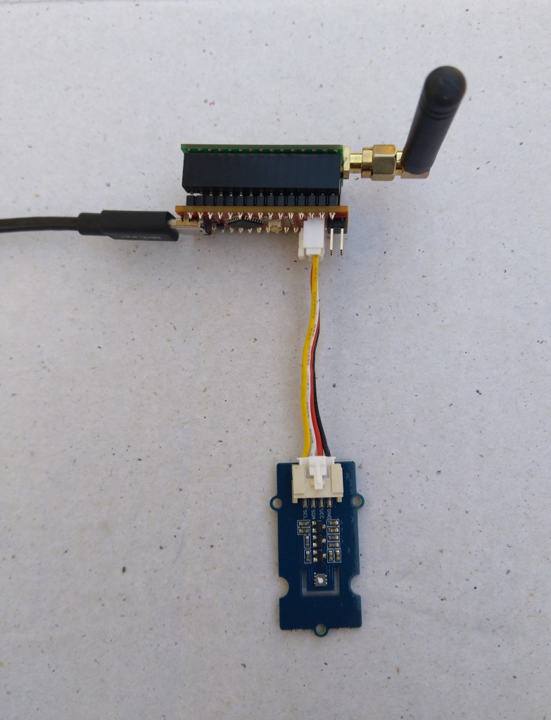
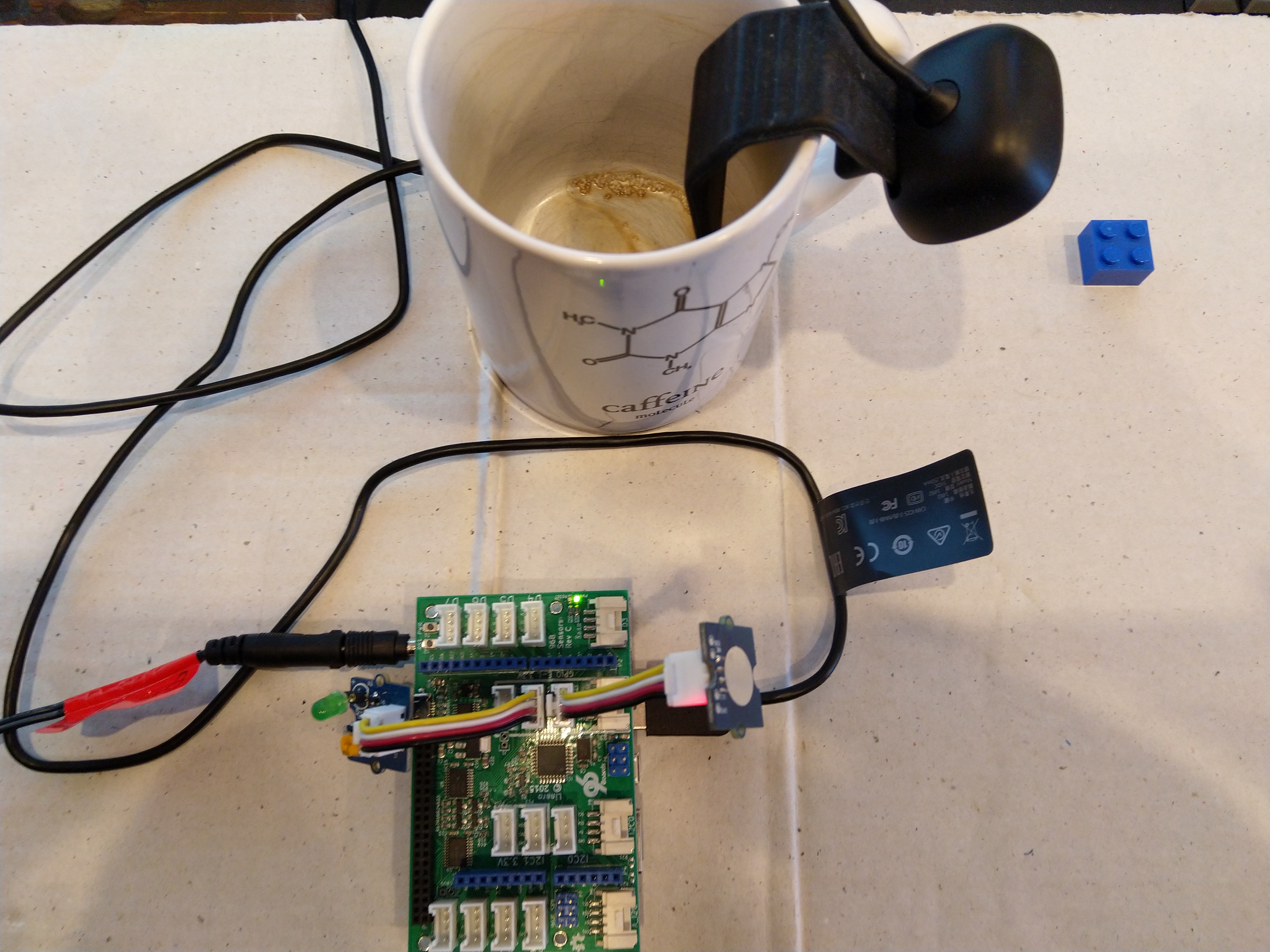
Seeeduino Nano easySensors shield and Grove VOC & eCO2 Sensor
Seeeduino Nano devices have a single on-board I2C socket which meant I didn’t need a Grove Shield for Arduino Nano which reduced the size and cost of the sensor node.
My first attempt failed with an issues accessing an Analog port to read the serial number from the Microchip ATSHA204 security chip. After looking at the Seeed SGP30 library source code (based on Sensiron samples) I think the my Nano device was running out of memory. I then searched for other Arduino compatible SGP30 libraries and rebuilt he application with the one from Sparkfun,
/*
  Copyright ® 2019 August devMobile Software, All Rights Reserved

  THIS CODE AND INFORMATION IS PROVIDED "AS IS" WITHOUT WARRANTY OF ANY
  KIND, EITHER EXPRESSED OR IMPLIED, INCLUDING BUT NOT LIMITED TO THE
  IMPLIED WARRANTIES OF MERCHANTABILITY AND/OR FITNESS FOR A PARTICULAR
  PURPOSE.

  You can do what you want with this code, acknowledgment would be nice.
  http://www.devmobile.co.nz

  Seeedstudio Grove - VOC and eCO2 Gas Sensor (SGP30)
  https://www.seeedstudio.com/Grove-VOC-and-eCO2-Gas-Sensor-SGP30-p-3071.html

  Seeeduino Nano
  https://www.seeedstudio.com/Seeeduino-Nano-p-4111.html

  Polycarbonate enclosure approx 3.5" x 4.5"
    2 x Cable glands
    1 x Grommet to seal SMA antenna connector
    3M command adhesive strips to hold battery & device in place

*/
#include <stdlib.h>
#include "SparkFun_SGP30_Arduino_Library.h"
#include <LoRa.h>
#include <sha204_library.h>

//#define DEBUG
//#define DEBUG_TELEMETRY
//#define DEBUG_LORA
#define DEBUG_VOC_AND_CO2

#define UNITS_VOC "ppb"
#define UNITS_CO2 "ppm"

// LoRa field gateway configuration (these settings must match your field gateway)
const byte DeviceAddressMaximumLength = 15 ;
const char FieldGatewayAddress[] = {"LoRaIoT1"};
const float FieldGatewayFrequency =  915000000.0;
const byte FieldGatewaySyncWord = 0x12 ;

// Payload configuration
const int ChipSelectPin = 10;
const int ResetPin = 9;
const int InterruptPin = 2;

// LoRa radio payload configuration
const byte SensorIdValueSeperator = ' ' ;
const byte SensorReadingSeperator = ',' ;
const unsigned long SensorUploadDelay = 60000;

// ATSHA204 secure authentication, validation with crypto and hashing (currently only using for unique serial number)
const byte Atsha204Port = A3;
atsha204Class sha204(Atsha204Port);
const byte DeviceSerialNumberLength = 9 ;
byte deviceSerialNumber[DeviceSerialNumberLength] = {""};

SGP30 mySensor; //create an object of the SGP30 class

const byte PayloadSizeMaximum = 64 ;
byte payload[PayloadSizeMaximum];
byte payloadLength = 0 ;


void setup()
{
  Serial.begin(9600);

#ifdef DEBUG
  while (!Serial);
#endif

  Serial.println("Setup called");

  Serial.print("Field gateway:");
  Serial.print(FieldGatewayAddress ) ;
  Serial.print(" Frequency:");
  Serial.print( FieldGatewayFrequency,0 ) ;
  Serial.print("MHz SyncWord:");
  Serial.print( FieldGatewaySyncWord ) ;
  Serial.println();

   // Retrieve the serial number then display it nicely
  if(sha204.getSerialNumber(deviceSerialNumber))
  {
    Serial.println("sha204.getSerialNumber failed");
    while (true); // Drop into endless loop requiring restart
  }

  Serial.print("SNo:");
  DisplayHex( deviceSerialNumber, DeviceSerialNumberLength);
  Serial.println();

  Serial.println("LoRa setup start");

  // override the default chip select and reset pins
  LoRa.setPins(ChipSelectPin, ResetPin, InterruptPin);
  if (!LoRa.begin(FieldGatewayFrequency))
  {
    Serial.println("LoRa begin failed");
    while (true); // Drop into endless loop requiring restart
  }

  // Need to do this so field gateway pays attention to messsages from this device
  LoRa.enableCrc();
  LoRa.setSyncWord(FieldGatewaySyncWord);

#ifdef DEBUG_LORA
  LoRa.dumpRegisters(Serial);
#endif
  Serial.println("LoRa Setup done.");

  // Configure the DF Robot SHT20, temperature & humidity sensor
  Serial.println("SGP30 setup start");
  Wire.begin();
  if(mySensor.begin() == false)
  {
    Serial.println("SQP-30 initialisation failed");
    while (true); // Drop into endless loop requiring restart
  }
  mySensor.initAirQuality();
  delay(1000);
  Serial.println("SGP30 setup done");

  PayloadHeader((byte *)FieldGatewayAddress,strlen(FieldGatewayAddress), deviceSerialNumber, DeviceSerialNumberLength);

  Serial.println("Setup done");
  Serial.println();
}


void loop()
{
  unsigned long currentMilliseconds = millis();

  Serial.println("Loop called");

  mySensor.measureAirQuality();

  PayloadReset();

  PayloadAdd( "v", mySensor.TVOC, false);

  PayloadAdd( "c", mySensor.CO2, false);

  #ifdef DEBUG_VOC_AND_CO2
    Serial.print("VoC:");
    Serial.print( mySensor.TVOC ) ;
    Serial.print( UNITS_VOC ) ;
    Serial.print(" Co2:");
    Serial.print( mySensor.CO2 ) ;
    Serial.println( UNITS_CO2 ) ;
  #endif

  #ifdef DEBUG_TELEMETRY
    Serial.println();
    Serial.print("RFM9X/SX127X Payload length:");
    Serial.print(payloadLength);
    Serial.println(" bytes");
  #endif

  LoRa.beginPacket();
  LoRa.write(payload, payloadLength);
  LoRa.endPacket();

  Serial.println("Loop done");
  Serial.println();

  delay(SensorUploadDelay - (millis() - currentMilliseconds ));
}


void PayloadHeader( const byte *to, byte toAddressLength, const byte *from, byte fromAddressLength)
{
  byte addressesLength = toAddressLength + fromAddressLength ;

  payloadLength = 0 ;

  // prepare the payload header with "To" Address length (top nibble) and "From" address length (bottom nibble)

  payload[payloadLength] = (toAddressLength << 4) | fromAddressLength ;
  payloadLength += 1;

  // Copy the "To" address into payload
  memcpy(&payload[payloadLength], to, toAddressLength);
  payloadLength += toAddressLength ;

  // Copy the "From" into payload
  memcpy(&payload[payloadLength], from, fromAddressLength);
  payloadLength += fromAddressLength ;
}


void PayloadAdd( const char *sensorId, float value, byte decimalPlaces, bool last)
{
  byte sensorIdLength = strlen( sensorId ) ;

  memcpy( &payload[payloadLength], sensorId,  sensorIdLength) ;
  payloadLength += sensorIdLength ;
  payload[ payloadLength] = SensorIdValueSeperator;
  payloadLength += 1 ;
  payloadLength += strlen( dtostrf(value, -1, decimalPlaces, (char *)&payload[payloadLength]));
  if (!last)
  {
    payload[ payloadLength] = SensorReadingSeperator;
    payloadLength += 1 ;
  }

#ifdef DEBUG_TELEMETRY
  Serial.print("PayloadAdd float-payloadLength:");
  Serial.print( payloadLength);
  Serial.println( );
#endif
}


void PayloadAdd( char *sensorId, int value, bool last )
{
  byte sensorIdLength = strlen(sensorId) ;

  memcpy(&payload[payloadLength], sensorId,  sensorIdLength) ;
  payloadLength += sensorIdLength ;
  payload[ payloadLength] = SensorIdValueSeperator;
  payloadLength += 1 ;
  payloadLength += strlen(itoa( value,(char *)&payload[payloadLength],10));
  if (!last)
  {
    payload[ payloadLength] = SensorReadingSeperator;
    payloadLength += 1 ;
  }

#ifdef DEBUG_TELEMETRY
  Serial.print("PayloadAdd int-payloadLength:" );
  Serial.print(payloadLength);
  Serial.println( );
#endif
}


void PayloadAdd( char *sensorId, unsigned int value, bool last )
{
  byte sensorIdLength = strlen(sensorId) ;

  memcpy(&payload[payloadLength], sensorId,  sensorIdLength) ;
  payloadLength += sensorIdLength ;
  payload[ payloadLength] = SensorIdValueSeperator;
  payloadLength += 1 ;
  payloadLength += strlen(utoa( value,(char *)&payload[payloadLength],10));
  if (!last)
  {
    payload[ payloadLength] = SensorReadingSeperator;
    payloadLength += 1 ;
  }

#ifdef DEBUG_TELEMETRY
  Serial.print("PayloadAdd uint-payloadLength:");
  Serial.print(payloadLength);
  Serial.println( );
#endif
}


void PayloadReset()
{
  byte fromAddressLength = payload[0] & 0xf ;
  byte toAddressLength = payload[0] >> 4 ;

  payloadLength = toAddressLength + fromAddressLength + 1;
}


void DisplayHex( byte *byteArray, byte length)
{
  for (int i = 0; i < length ; i++)
  {
    // Add a leading zero
    if ( byteArray[i] < 16)
    {
      Serial.print("0");
    }
    Serial.print(byteArray[i], HEX);
    if ( i < (length-1)) // Don't put a - after last digit
    {
      Serial.print("-");
    }
  }
}
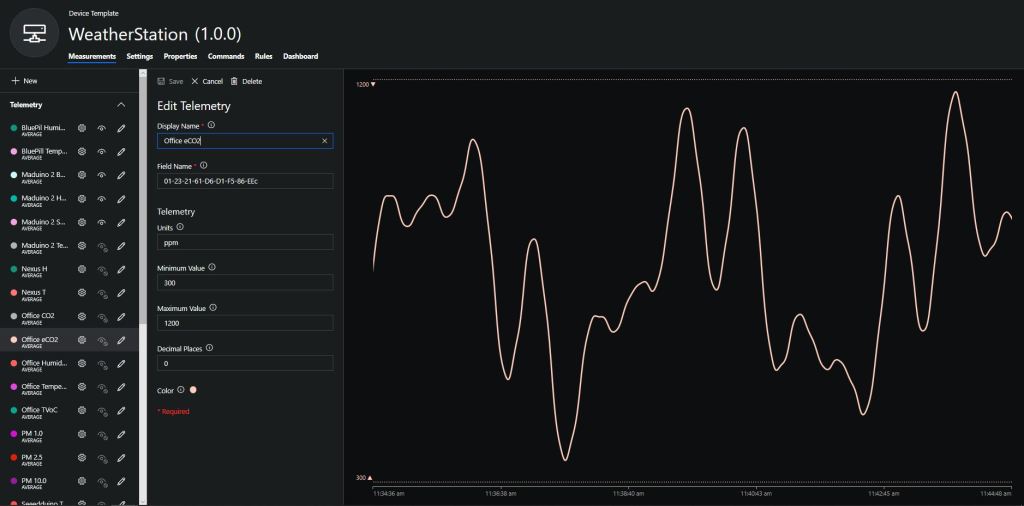
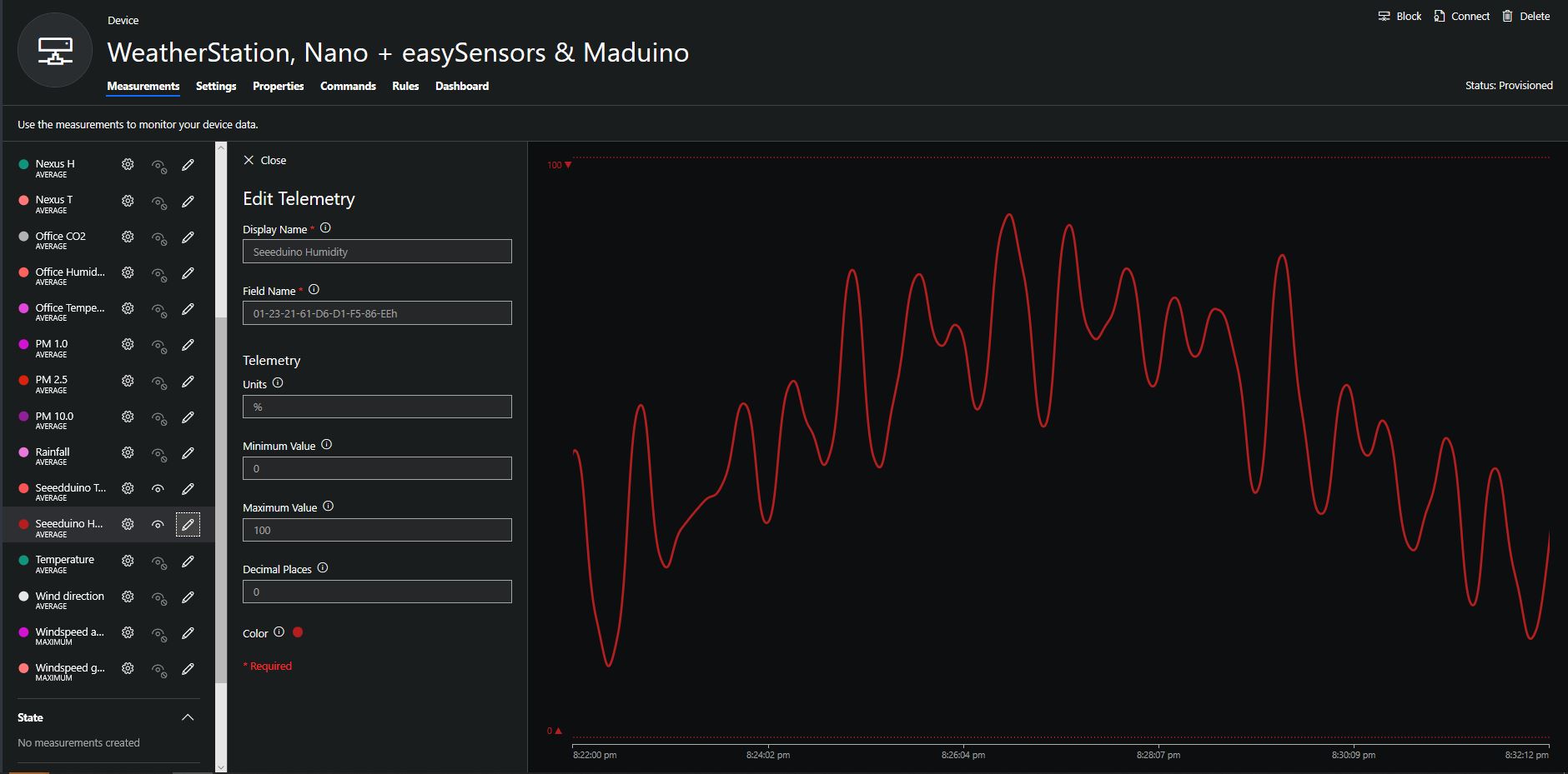
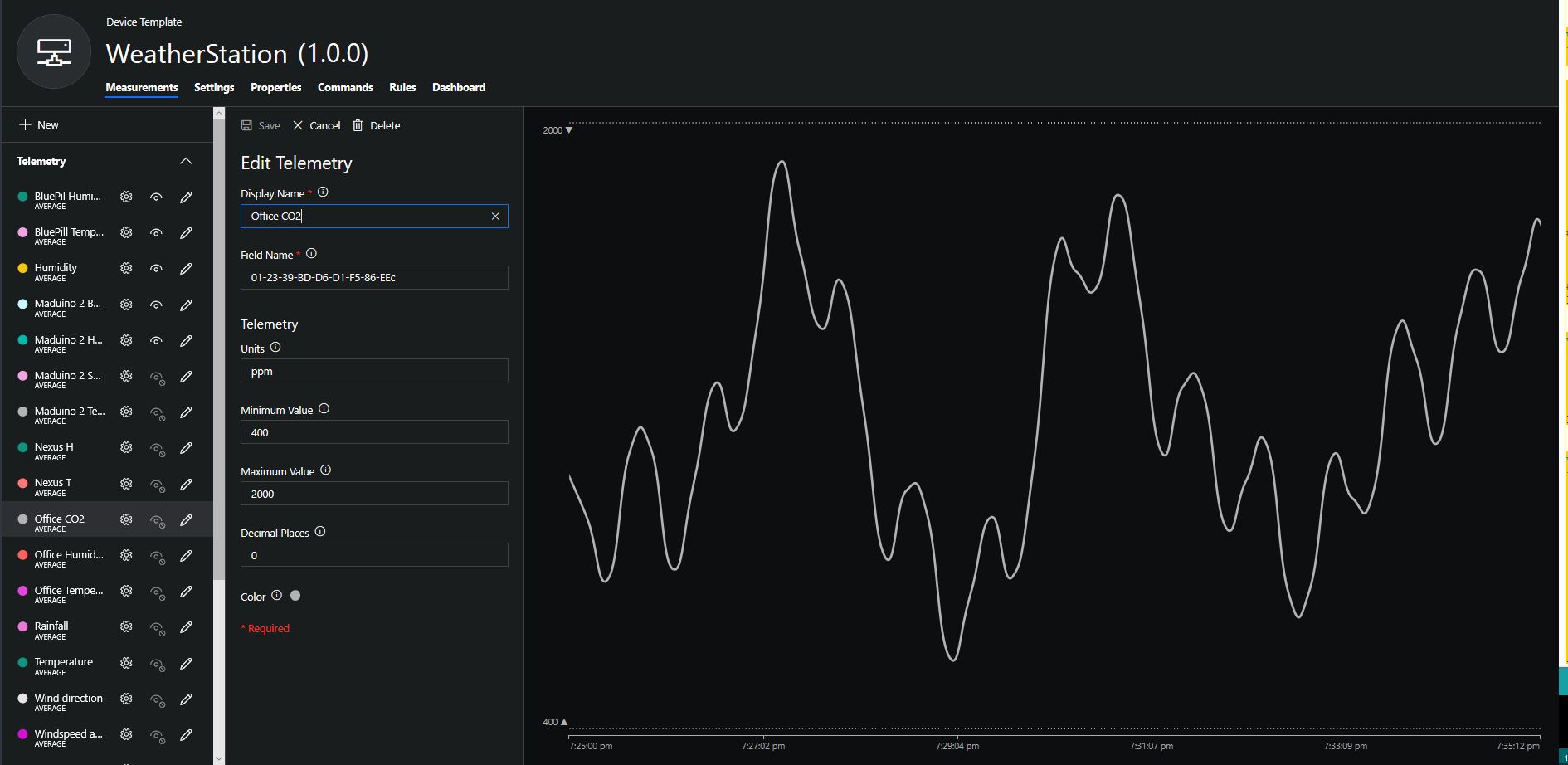
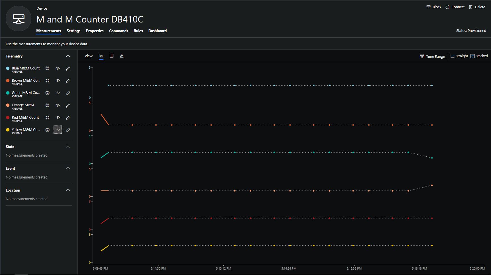
To configure the device in Azure IoT Central (similar process for Adafruit.IO, working on support for losant, and ubidots) I copied the SNo: from the Arduino development tool logging window and appended c for the CO2 parts per million (ppm), v for VOC parts per billion (ppb) unique serial number from the ATSHA204A chip. (N.B. pay attention to the case of the field names they are case sensitive)
Azure IoT Central configuration
Overall the performance of the VoC sensor data is looking pretty positive, the eCO2 readings need some further investigation as they track the VOC levels. The large spike in the graph below is me putting an open vivid marker on my desk near the sensor.
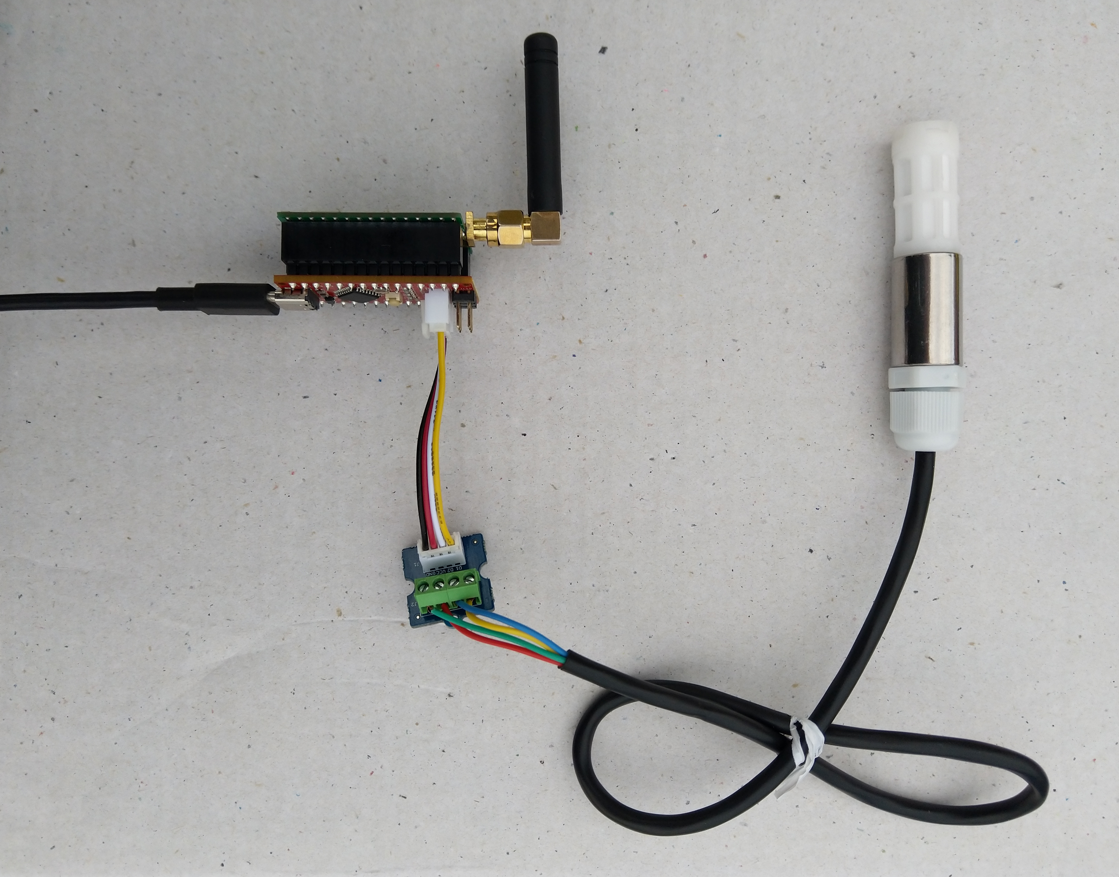
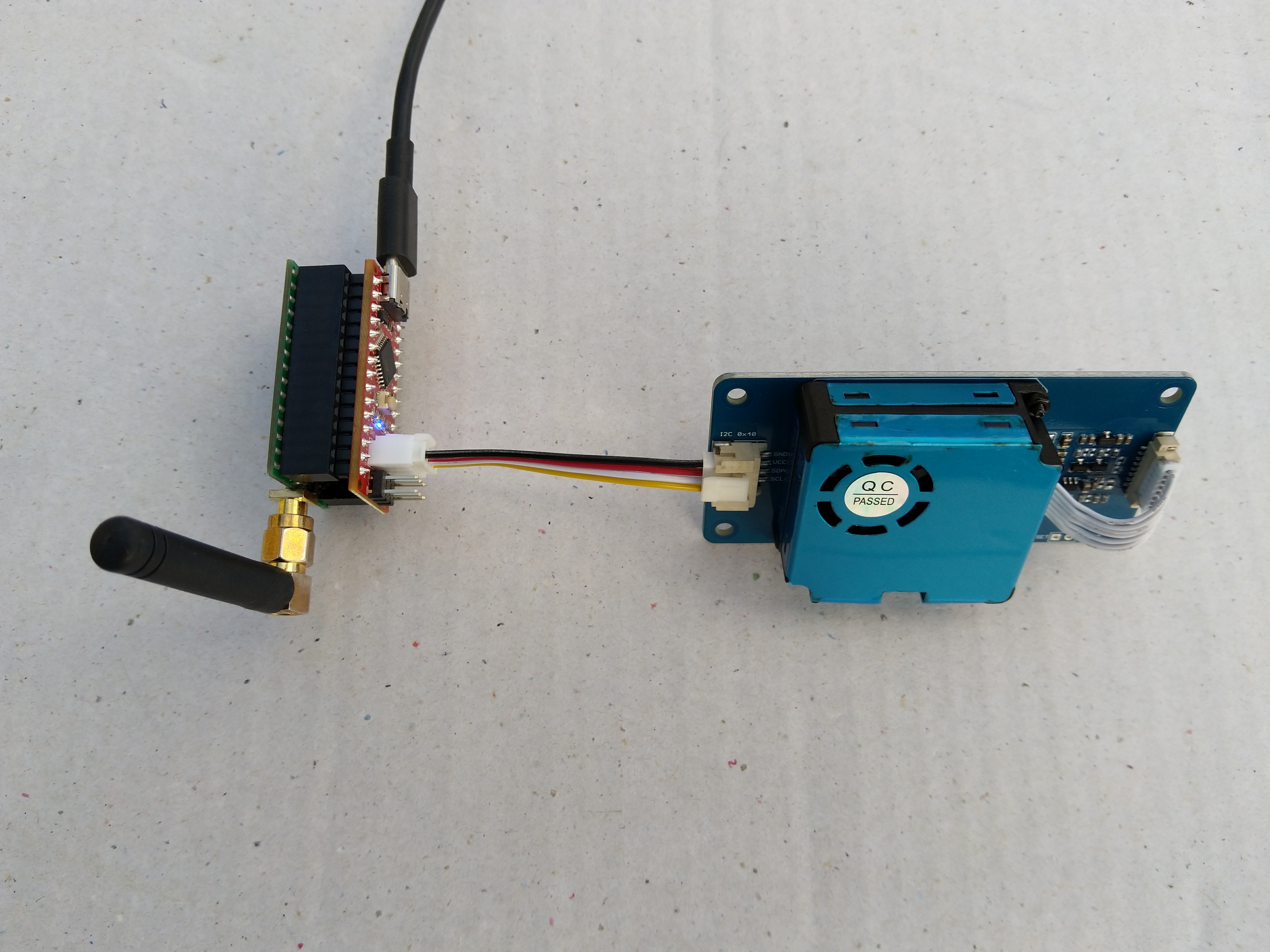
Seeeduino Nano, EasySensors Shield & DF Robot Sensor test rig
The Seeeduino Nano devices I’m testing have a single on-board I2C socket which meant I didn’t need a Grove Shield for Arduino Nano which reduced the size and cost of the sensor node.
To configure the device in Azure IoT Central (similar process for Adafruit.IO, working on support for losant,and ubidots I copied the SNo: from the Arduino development tool logging window and appended p10 for PM 1 value, p25 for PM2.5 value and p100 for PM10 value to the unique serial number from the ATSHA204A chip. (N.B. pay attention to the case of the field names they are case sensitive)
When I moved the sensor indoors it appeared to take a while to warm up and after a while the metal body still felt cold. The sensor element is surrounded by quite a bit of protective packaging for outdoors use and I that would have a bit more thermal inertia the than the lightweight indoor enclosure.
It would be good to run the sensor alongside a calibrated temperature & humidity sensor to see how accurate and responsive it is.
The Seeeduino Nano devices I’m testing have a single on-board I2C socket which meant I didn’t need a Grove Shield for Arduino Nano which reduced the size and cost of the sensor node.
After looking at the demo application I stripped out the checksum code and threw the rest away. In my test harness I have extracted only the PM1.0/PM2.5/PM10.0 (concentration CF=1, Standard particulate) in μg/ m3 values from the sensor response payload.
/*
  Copyright ® 2019 August devMobile Software, All Rights Reserved

  THIS CODE AND INFORMATION IS PROVIDED "AS IS" WITHOUT WARRANTY OF ANY
  KIND, EITHER EXPRESSED OR IMPLIED, INCLUDING BUT NOT LIMITED TO THE
  IMPLIED WARRANTIES OF MERCHANTABILITY AND/OR FITNESS FOR A PARTICULAR
  PURPOSE.

  You can do what you want with this code, acknowledgment would be nice.

  http://www.devmobile.co.nz

*/
#include <stdlib.h>
#include <LoRa.h>
#include <sha204_library.h>
#include "Seeed_HM330X.h"

//#define DEBUG
//#define DEBUG_TELEMETRY
//#define DEBUG_LORA

const byte SensorPayloadLength = 28 ;
const byte SensorPayloadBufferSize  = 29 ;
const byte SensorPayloadPM1_0Position = 4;
const byte SensorPayloadPM2_5Position = 6;
const byte SensorPayloadPM10_0Position = 8;

HM330X sensor;
byte SensorPayload[SensorPayloadBufferSize];

// LoRa field gateway configuration (these settings must match your field gateway)
const byte DeviceAddressMaximumLength = 15 ;
const char FieldGatewayAddress[] = {"LoRaIoT1"};
const float FieldGatewayFrequency =  915000000.0;
const byte FieldGatewaySyncWord = 0x12 ;

// Payload configuration
const int ChipSelectPin = 10;
const int ResetPin = 9;
const int InterruptPin = 2;

// LoRa radio payload configuration
const byte SensorIdValueSeperator = ' ' ;
const byte SensorReadingSeperator = ',' ;
const unsigned long SensorUploadDelay = 60000;

// ATSHA204 secure authentication, validation with crypto and hashing (currently only using for unique serial number)
const byte Atsha204Port = A3;
atsha204Class sha204(Atsha204Port);
const byte DeviceSerialNumberLength = 9 ;
byte deviceSerialNumber[DeviceSerialNumberLength] = {""};

const byte PayloadSizeMaximum = 64 ;
byte payload[PayloadSizeMaximum];
byte payloadLength = 0 ;


void setup()
{
  Serial.begin(9600);

#ifdef DEBUG
  while (!Serial);
#endif

  Serial.println("Setup called");

  Serial.print("Field gateway:");
  Serial.print(FieldGatewayAddress ) ;
  Serial.print(" Frequency:");
  Serial.print( FieldGatewayFrequency,0 ) ;
  Serial.print("MHz SyncWord:");
  Serial.print( FieldGatewaySyncWord ) ;
  Serial.println();

   // Retrieve the serial number then display it nicely
  if(sha204.getSerialNumber(deviceSerialNumber))
  {
    Serial.println("sha204.getSerialNumber failed");
    while (true); // Drop into endless loop requiring restart
  }

  Serial.print("SNo:");
  DisplayHex( deviceSerialNumber, DeviceSerialNumberLength);
  Serial.println();

  Serial.println("LoRa setup start");

  // override the default chip select and reset pins
  LoRa.setPins(ChipSelectPin, ResetPin, InterruptPin);
  if (!LoRa.begin(FieldGatewayFrequency))
  {
    Serial.println("LoRa begin failed");
    while (true); // Drop into endless loop requiring restart
  }

  // Need to do this so field gateway pays attention to messsages from this device
  LoRa.enableCrc();
  LoRa.setSyncWord(FieldGatewaySyncWord);

#ifdef DEBUG_LORA
  LoRa.dumpRegisters(Serial);
#endif
  Serial.println("LoRa Setup done.");

  // Configure the Seeedstudio CO2, temperature & humidity sensor
  Serial.println("HM3301 setup start");
  if(sensor.init())
  {
    Serial.println("HM3301 init failed");
    while (true); // Drop into endless loop requiring restart

  }
  delay(100);
  Serial.println("HM3301 setup done");

  PayloadHeader((byte *)FieldGatewayAddress,strlen(FieldGatewayAddress), deviceSerialNumber, DeviceSerialNumberLength);

  Serial.println("Setup done");
  Serial.println();
}

void loop()
{
  unsigned long currentMilliseconds = millis();
  byte sum=0;
  short pm1_0 ;
  short pm2_5 ;
  short pm10_0 ;

  Serial.println("Loop called");

  if(sensor.read_sensor_value(SensorPayload,SensorPayloadBufferSize) == NO_ERROR)
  {
    // Calculate then validate the payload "checksum"
    for(int i=0;i<SensorPayloadLength;i++)
    {
        sum+=SensorPayload[i];
    }
    if(sum!=SensorPayload[SensorPayloadLength])
    {
        Serial.println("Invalid checksum");
        return;
    }

    PayloadReset();

    pm1_0 = (u16)SensorPayload[SensorPayloadPM1_0Position]<<8|SensorPayload[SensorPayloadPM1_0Position+1];
    Serial.print("PM1.5: ");
    Serial.print(pm1_0);
    Serial.println("ug/m3 ") ;

    PayloadAdd( "P10", pm1_0, false);

    pm2_5 = (u16)SensorPayload[SensorPayloadPM2_5Position]<<8|SensorPayload[SensorPayloadPM2_5Position+1];
    Serial.print("PM2.5: ");
    Serial.print(pm2_5);
    Serial.println("ug/m3 ") ;

    PayloadAdd( "P25", pm2_5, 1, false);

    pm10_0 = (u16)SensorPayload[SensorPayloadPM10_0Position]<<8|SensorPayload[SensorPayloadPM10_0Position+1];
    Serial.print("PM10.0: ");
    Serial.print(pm10_0);
    Serial.println("ug/m3 ");

    PayloadAdd( "P100", pm10_0, 0, true) ;

    #ifdef DEBUG_TELEMETRY
      Serial.println();
      Serial.print("RFM9X/SX127X Payload length:");
      Serial.print(payloadLength);
      Serial.println(" bytes");
    #endif

    LoRa.beginPacket();
    LoRa.write(payload, payloadLength);
    LoRa.endPacket();
  }
  Serial.println("Loop done");
  Serial.println();

  delay(SensorUploadDelay - (millis() - currentMilliseconds ));
}

void PayloadHeader( const byte *to, byte toAddressLength, const byte *from, byte fromAddressLength)
{
  byte addressesLength = toAddressLength + fromAddressLength ;

  payloadLength = 0 ;

  // prepare the payload header with "To" Address length (top nibble) and "From" address length (bottom nibble)

  payload[payloadLength] = (toAddressLength << 4) | fromAddressLength ;
  payloadLength += 1;

  // Copy the "To" address into payload
  memcpy(&payload[payloadLength], to, toAddressLength);
  payloadLength += toAddressLength ;

  // Copy the "From" into payload
  memcpy(&payload[payloadLength], from, fromAddressLength);
  payloadLength += fromAddressLength ;
}

void PayloadAdd( const char *sensorId, float value, byte decimalPlaces, bool last)
{
  byte sensorIdLength = strlen( sensorId ) ;

  memcpy( &payload[payloadLength], sensorId,  sensorIdLength) ;
  payloadLength += sensorIdLength ;
  payload[ payloadLength] = SensorIdValueSeperator;
  payloadLength += 1 ;
  payloadLength += strlen( dtostrf(value, -1, decimalPlaces, (char *)&payload[payloadLength]));
  if (!last)
  {
    payload[ payloadLength] = SensorReadingSeperator;
    payloadLength += 1 ;
  }

#ifdef DEBUG_TELEMETRY
  Serial.print("PayloadAdd float-payloadLength:");
  Serial.print( payloadLength);
  Serial.println( );
#endif
}

void PayloadAdd( char *sensorId, int value, bool last )
{
  byte sensorIdLength = strlen(sensorId) ;

  memcpy(&payload[payloadLength], sensorId,  sensorIdLength) ;
  payloadLength += sensorIdLength ;
  payload[ payloadLength] = SensorIdValueSeperator;
  payloadLength += 1 ;
  payloadLength += strlen(itoa( value,(char *)&payload[payloadLength],10));
  if (!last)
  {
    payload[ payloadLength] = SensorReadingSeperator;
    payloadLength += 1 ;
  }

#ifdef DEBUG_TELEMETRY
  Serial.print("PayloadAdd int-payloadLength:" );
  Serial.print(payloadLength);
  Serial.println( );
#endif
}

void PayloadAdd( char *sensorId, unsigned int value, bool last )
{
  byte sensorIdLength = strlen(sensorId) ;

  memcpy(&payload[payloadLength], sensorId,  sensorIdLength) ;
  payloadLength += sensorIdLength ;
  payload[ payloadLength] = SensorIdValueSeperator;
  payloadLength += 1 ;
  payloadLength += strlen(utoa( value,(char *)&payload[payloadLength],10));
  if (!last)
  {
    payload[ payloadLength] = SensorReadingSeperator;
    payloadLength += 1 ;
  }

#ifdef DEBUG_TELEMETRY
  Serial.print("PayloadAdd uint-payloadLength:");
  Serial.print(payloadLength);
  Serial.println( );
#endif
}

void PayloadReset()
{
  byte fromAddressLength = payload[0] & 0xf ;
  byte toAddressLength = payload[0] >> 4 ;

  payloadLength = toAddressLength + fromAddressLength + 1;
}

void DisplayHex( byte *byteArray, byte length)
{
  for (int i = 0; i < length ; i++)
  {
    // Add a leading zero
    if ( byteArray[i] < 16)
    {
      Serial.print("0");
    }
    Serial.print(byteArray[i], HEX);
    if ( i < (length-1)) // Don't put a - after last digit
    {
      Serial.print("-");
    }
  }
}
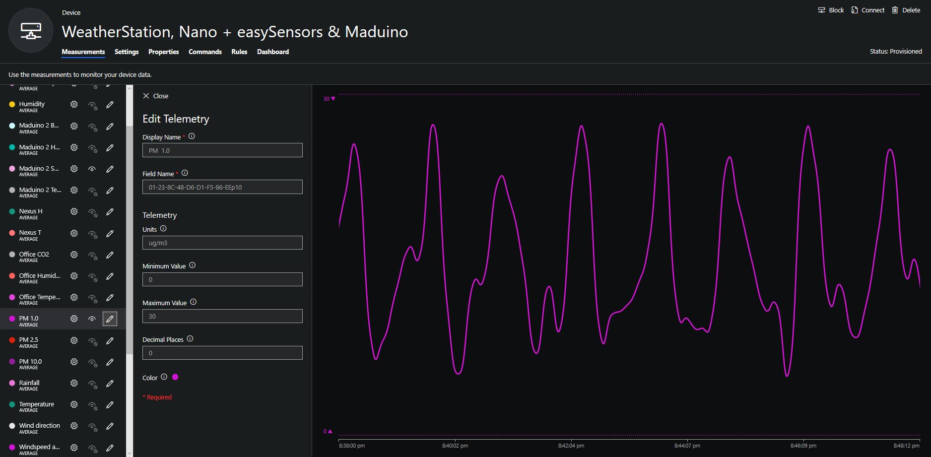
To configure the device in Azure IoT Central (similar process for Adafruit.IO, working on support for losant, and ubidots) I copied the SNo: from the Arduino development tool logging window and appended p10 for PM 1 value, p25 for PM2.5 value and p100 for PM10 value to the unique serial number from the ATSHA204A chip. (N.B. pay attention to the case of the field names they are case sensitive)
Azure IoT Central telemetry configuration
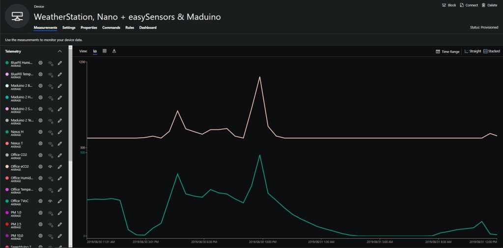
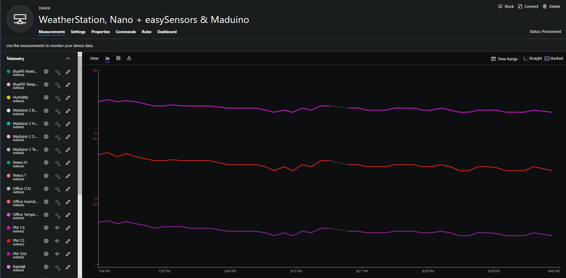
The rapidly settled into a narrow range of readings, but spiked when I took left it outside (winter in New Zealand) and the values spiked when food was being cooked in the kitchen which is next door to my office.
It would be good to run the sensor alongside a professional particulates monitor so the values could be compared and used to adjust the readings of the Grove sensor if necessary.
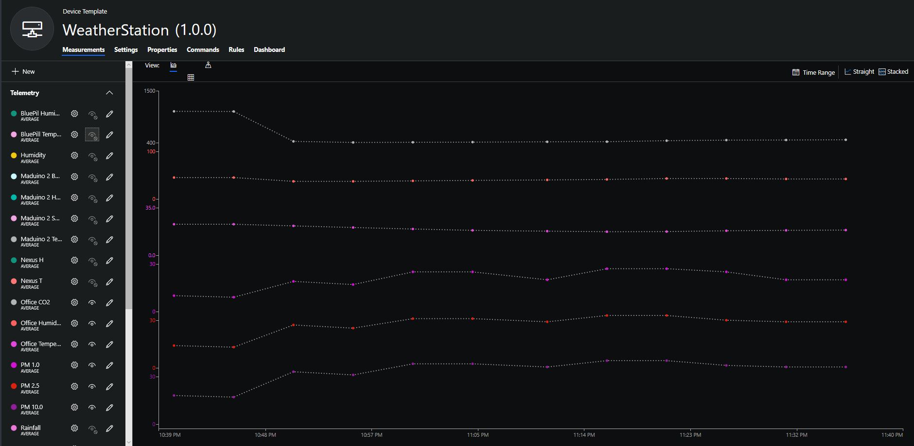
Hour of PM1, PM2.5 & PM10 readings in my office early eveningCO2 and particulates values while outside on my deck from 10:30pm to 11:30pm
Seeeduino Nano devices have a single on-board I2C socket which meant I didn’t need a Grove Shield for Arduino Nano which reduced the size and cost of the sensor node.
I downloaded the seeedstudio wiki example calibration code, compiled and uploaded it to one of my Seeeduino Nano devices. When activated for the first time a period of minimum 7 days is needed so that the sensor algorithm can find its initial parameter set. During this period the sensor has to be exposed to fresh air for at least 1 hour every day.
During the calibration process I put the device in my garage and left the big door open for at least an hour every day. Once the sensor was calibrated I bought it inside at put it on the bookcase in my office.
To configure the device in Azure IoT Central (similar process for Adafruit.IO, working on support for losant, and ubidots) I copied the SNo: from the Arduino development tool logging window and appended c for the CO2 parts per million (ppm), h for the humidity % and t for the temperature °C to the unique serial number from the ATSHA204A chip. (N.B. pay attention to the case of the field names they are case sensitive)
Azure IoT Central telemetry configuration
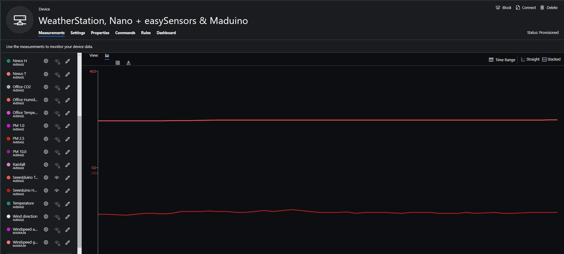
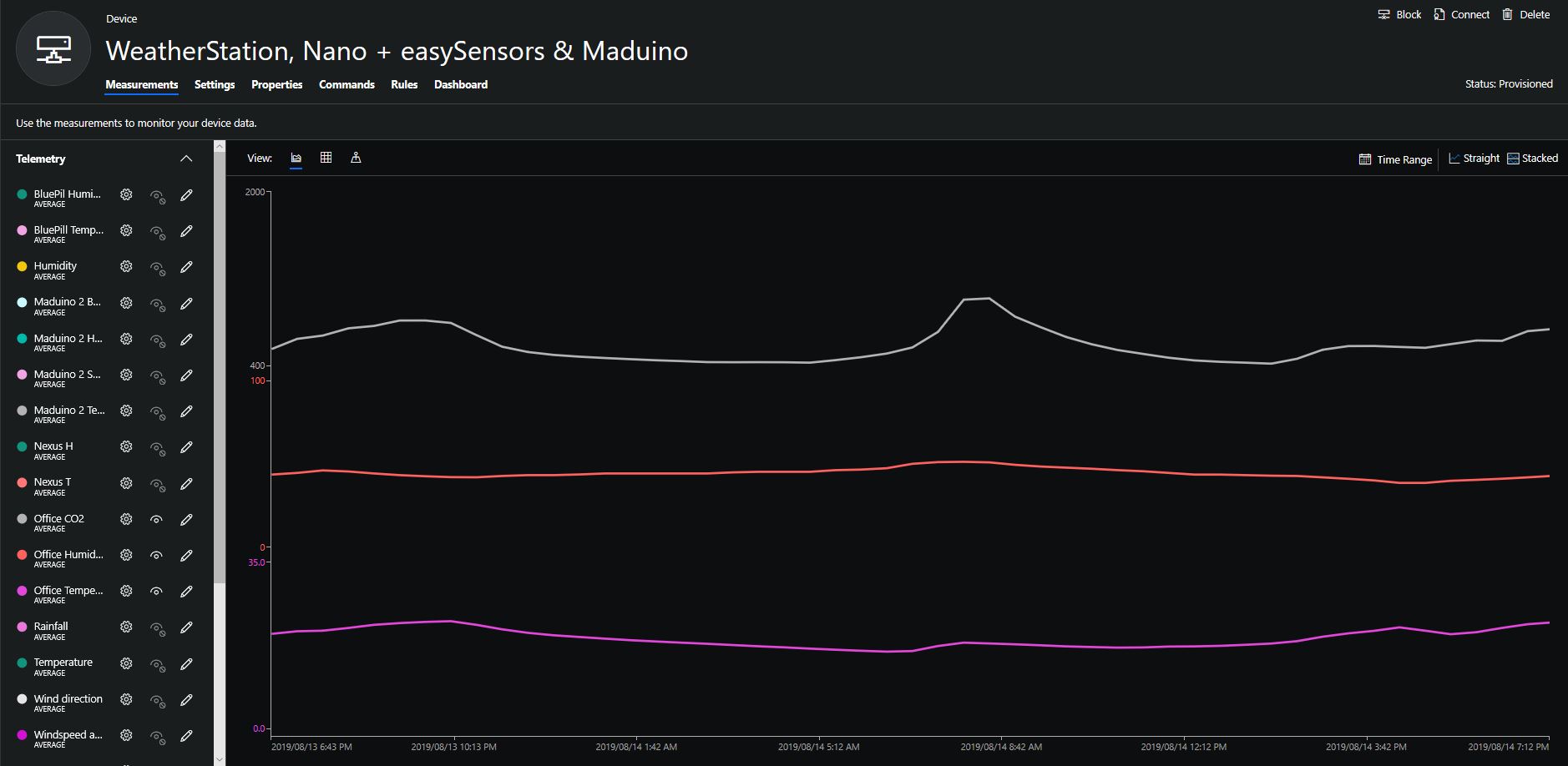
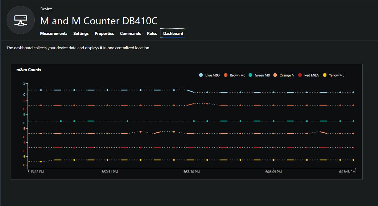
Overall the performance of the sensor is looking pretty positive, the CO2 levels fluctuate in a acceptable range (based on office occupancy), and the temperature + humidity readings track quite closely to the other two sensor nodes in my office. The only issue so far is my lack of USB-C cables to power the devices in the field
CO2, Humidity and Temperature in my office for a day
try
{
	this.azureIoTHubClient = DeviceClient.CreateFromConnectionString(this.azureIoTHubConnectionString, this.transportType);
}
catch (Exception ex)
{
	this.logging.LogMessage("AzureIOT Hub DeviceClient.CreateFromConnectionString failed " + ex.Message, LoggingLevel.Error);
	return;
}

try
{
	TwinCollection reportedProperties = new TwinCollection();

	// This is from the OS
	reportedProperties["Timezone"] = TimeZoneSettings.CurrentTimeZoneDisplayName;
	reportedProperties["OSVersion"] = Environment.OSVersion.VersionString;
	reportedProperties["MachineName"] = Environment.MachineName;

	reportedProperties["ApplicationDisplayName"] = package.DisplayName;
	reportedProperties["ApplicationName"] = packageId.Name;
	reportedProperties["ApplicationVersion"] = string.Format($"{version.Major}.{version.Minor}.{version.Build}.{version.Revision}");

	// Unique identifier from the hardware
	SystemIdentificationInfo systemIdentificationInfo = SystemIdentification.GetSystemIdForPublisher();
	using (DataReader reader = DataReader.FromBuffer(systemIdentificationInfo.Id))
	{
		byte[] bytes = new byte[systemIdentificationInfo.Id.Length];
		reader.ReadBytes(bytes);
		reportedProperties["SystemId"] = BitConverter.ToString(bytes);
	}
	this.azureIoTHubClient.UpdateReportedPropertiesAsync(reportedProperties).Wait();
}
catch (Exception ex)
{
	this.logging.LogMessage("Azure IoT Hub client UpdateReportedPropertiesAsync failed " + ex.Message, LoggingLevel.Error);
	return;
}

try
{
	LoggingFields configurationInformation = new LoggingFields();

	Twin deviceTwin = this.azureIoTHubClient.GetTwinAsync().GetAwaiter().GetResult();

	if (!deviceTwin.Properties.Desired.Contains("ImageUpdateDue") || !TimeSpan.TryParse(deviceTwin.Properties.Desired["ImageUpdateDue"].value.ToString(), out imageUpdateDue))
	{
		this.logging.LogMessage("DeviceTwin.Properties ImageUpdateDue setting missing or invalid format", LoggingLevel.Warning);
		return;
	}
	configurationInformation.AddTimeSpan("ImageUpdateDue", imageUpdateDue);

	if (!deviceTwin.Properties.Desired.Contains("ImageUpdatePeriod") || !TimeSpan.TryParse(deviceTwin.Properties.Desired["ImageUpdatePeriod"].value.ToString(), out imageUpdatePeriod))
	{
		this.logging.LogMessage("DeviceTwin.Properties ImageUpdatePeriod setting missing or invalid format", LoggingLevel.Warning);
		return;
	}
…
	if (!deviceTwin.Properties.Desired.Contains("DebounceTimeout") || !TimeSpan.TryParse(deviceTwin.Properties.Desired["DebounceTimeout"].value.ToString(), out debounceTimeout))
	{
		this.logging.LogMessage("DeviceTwin.Properties DebounceTimeout setting missing or invalid format", LoggingLevel.Warning);
		return;
	}
				configurationInformation.AddTimeSpan("DebounceTimeout", debounceTimeout);

	this.logging.LogEvent("Configuration settings", configurationInformation);
}
catch (Exception ex)
{
	this.logging.LogMessage("Azure IoT Hub client GetTwinAsync failed or property missing/invalid" + ex.Message, LoggingLevel.Error);
	return;
}
When the digital input (configured in the app.settings file) is strobed or the timer fires (configured in the device properties) an image is captured, uploaded to Azure Cognitive Services Custom Vision for processing.
The returned results are then post processed to make them Azure IoT Central friendly, and finally uploaded to an Azure IoT Hub.
For testing I have used a simple object detection model.
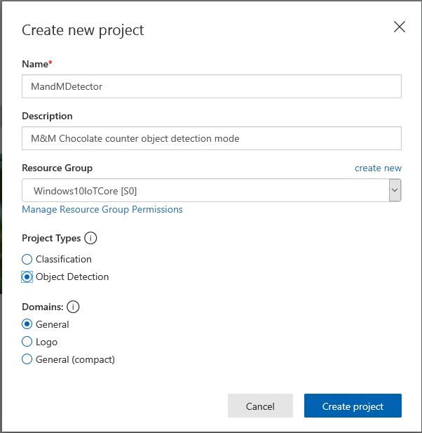
I trained the model with images of 6 different colours of m&m’s.
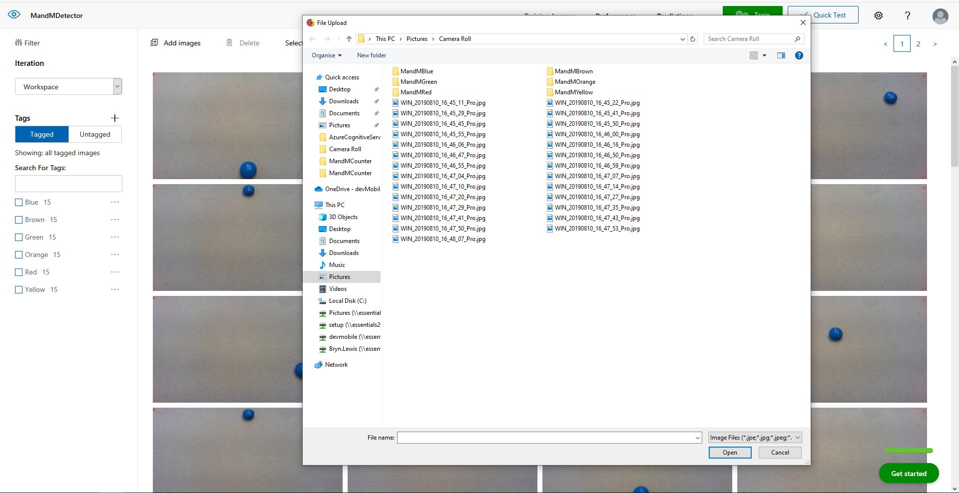
For my first dataset I tagged the location of a single m&m of each of the colour in 15 images.
Testing the training of the model
I then trained the model multiple times adding additional images where the model was having trouble distiguishing colours.
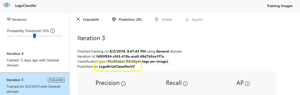
The published name comes from the training performance tab
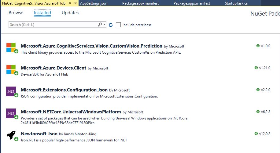
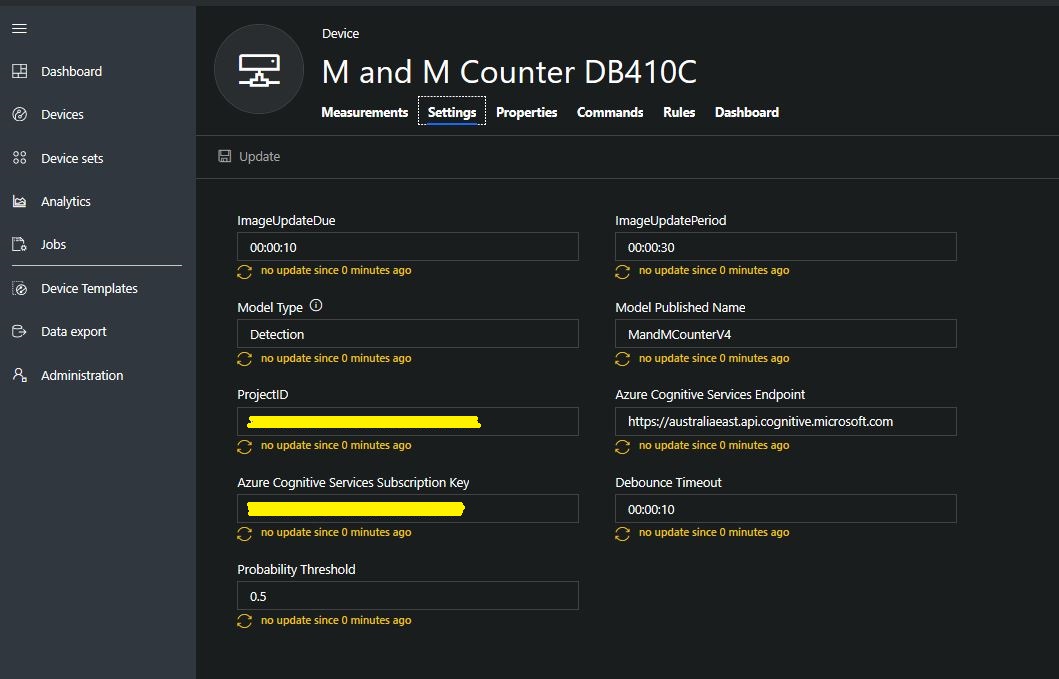
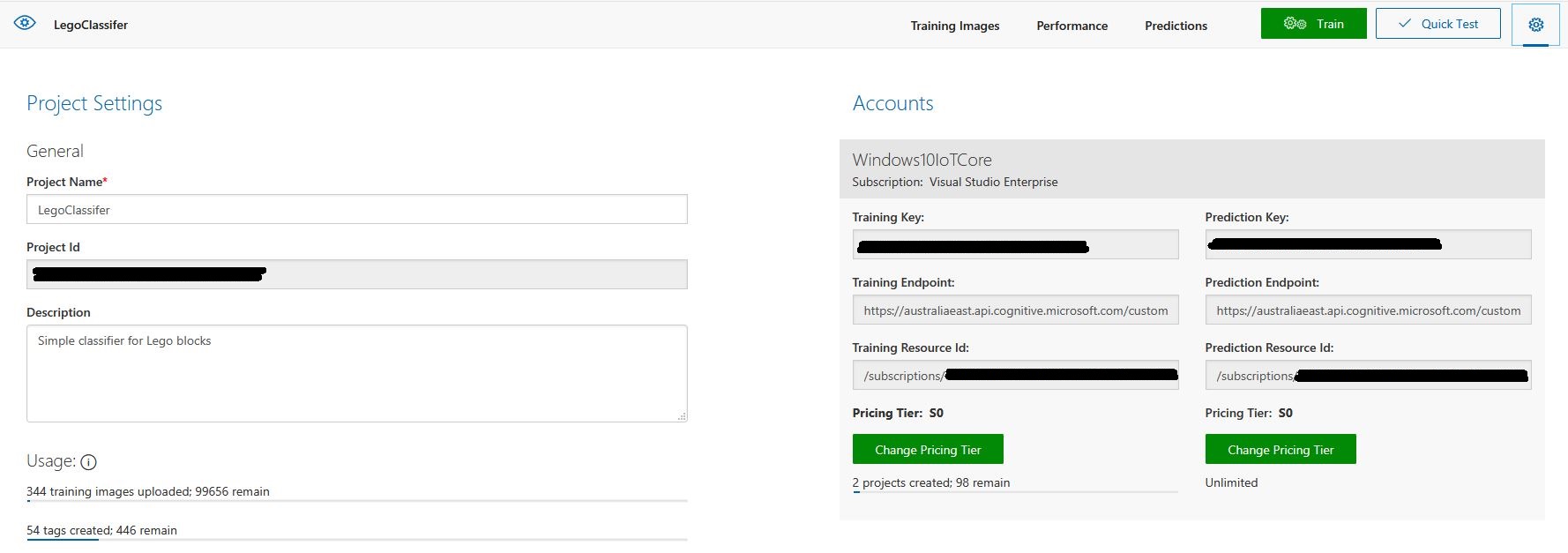
Project settings
The projectID, AzureCognitiveServicesSubscriptionKey (PredictionKey) and PublishedName (From the Performance tab in project) are from the custom vision project properties.
All of the Custom Vision model settings are configured in the Azure IoT Hub device properties.
The app.settings file contains only the hardware configuration settings and the Azure IoT Hub connection string.
The LED connected to the display pin is illuminated while an image is being processed or briefly flashed if the insufficient time between image captures has passed.
The image data is post processed differently based on the model.
// Post process the predictions based on the type of model
switch (modelType)
{
	case ModelType.Classification:
		// Use only the tags above the specified minimum probability
		foreach (var prediction in imagePrediction.Predictions)
		{
			if (prediction.Probability >= probabilityThreshold)
			{
				// Display and log the individual tag probabilities
				Debug.WriteLine($" Tag valid:{prediction.TagName} {prediction.Probability:0.00}");
				imageInformation.AddDouble($"Tag valid:{prediction.TagName}", prediction.Probability);
					telemetryDataPoint.Add(prediction.TagName, prediction.Probability);
			}
		}
		break;

	case ModelType.Detection:
		// Group the tags to get the count, include only the predictions above the specified minimum probability
		var groupedPredictions = from prediction in imagePrediction.Predictions
										 where prediction.Probability >= probabilityThreshold
										 group prediction by new { prediction.TagName }
				into newGroup
										 select new
										 {
											 TagName = newGroup.Key.TagName,
											 Count = newGroup.Count(),
										 };

		// Display and log the agregated predictions
		foreach (var prediction in groupedPredictions)
		{
			Debug.WriteLine($" Tag valid:{prediction.TagName} {prediction.Count}");
			imageInformation.AddInt32($"Tag valid:{prediction.TagName}", prediction.Count);
			telemetryDataPoint.Add(prediction.TagName, prediction.Count);
		}
		break;
	default:
		throw new ArgumentException("ModelType Invalid");
}
For a classifier only the tags with a probability greater than or equal the specified threshold are uploaded.
For a detection model the instances of each tag are counted. Only the tags with a prediction value greater than the specified threshold are included in the count.
The debugging output of the application includes the different categories identified in the captured image.
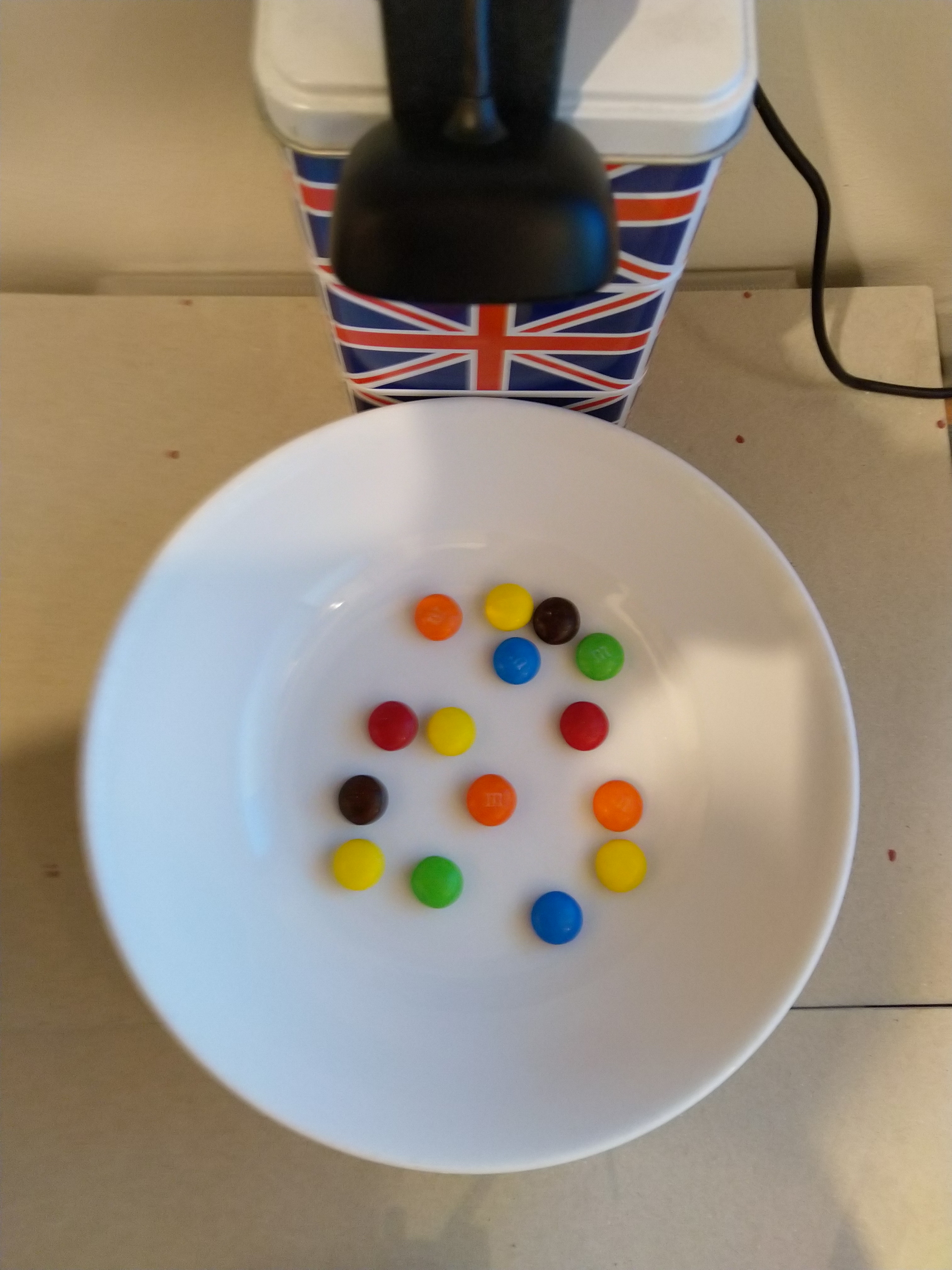
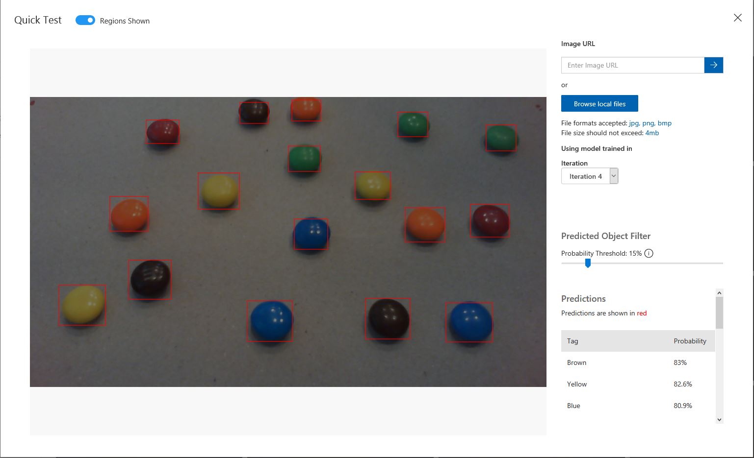
I found my small model was pretty good at detection of individual m&m as long as the ambient lighting was consistent, and the background fairly plain.
Sample image from test rig
Every so often the camera contrast setting went bad and could only be restored by restarting the device which needs further investigation.
Image with contrast problem
This application could be the basis for projects which need to run an Azure Cognitive Services model to count or classify then upload the results to an Azure IoT Hub or Azure IoT Central for presentation.
With a suitable model this application could be used to count the number of people in a room, which could be displayed along with the ambient temperature, humidity, CO2, and noise levels in Azure IoT Central.
The code for this application is available In on GitHub.
This application was inspired by one of teachers I work with wanting to count ducks in the stream on the school grounds. The school was having problems with water quality and the they wanted to see if the number of ducks was a factor. (Manually counting the ducks several times a day would be impractical).
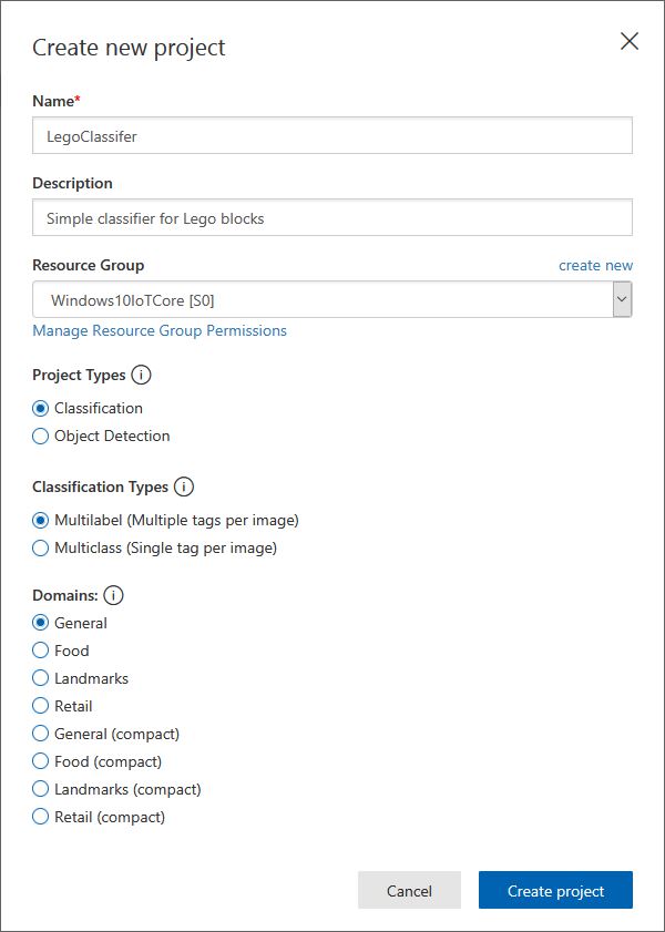
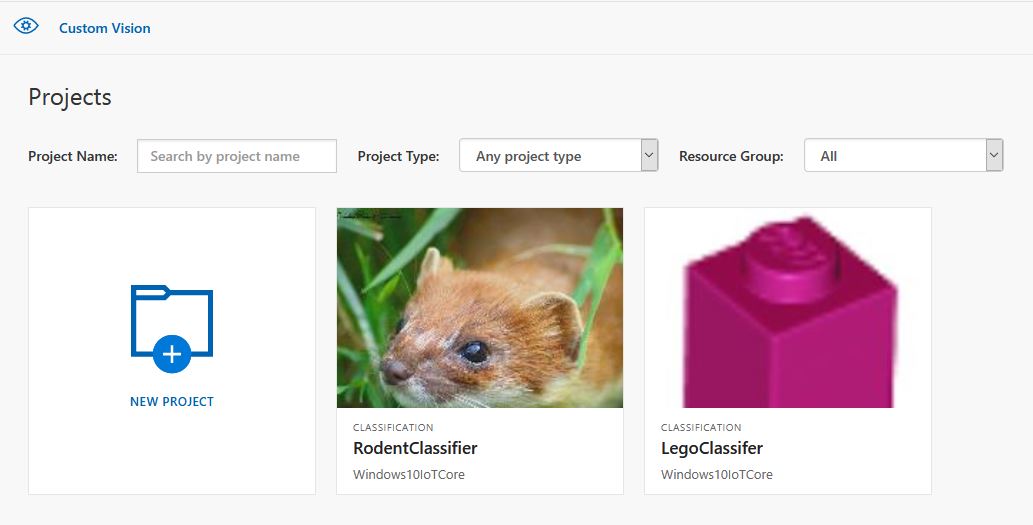
I didn’t have a source of training images so built an image classifier using my son’s Lego for testing. In a future post I will build an object detection model once I have some sample images of the stream captured by my Windows 10 IoT Core time lapse camera application.
Every time the digital input is strobed by the infra red proximity sensor or touch button an image is captured, uploaded for processing, and results displayed in the debug output.
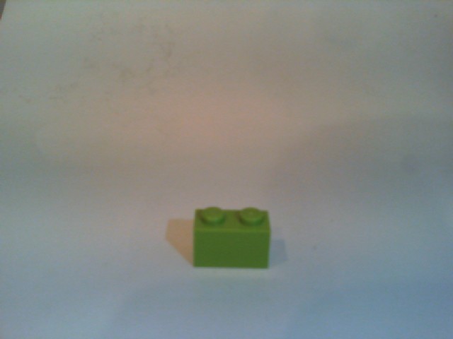
For testing I have used a simple multiclass classifier that I trained with a selection of my son’s Lego. I tagged the brick size height x width x length (1x2x3, smallest of width/height first) and colour (red, green, blue etc.)
The projectID, AzureCognitiveServicesSubscriptionKey (PredictionKey) and PublishedName (From the Performance tab in project) in the app.settings file come from the custom vision project properties.
The sample application only supports one trigger tag + probability and if this condition satisfied the Light Emitting Diode (LED) is turned on for 5 seconds. If an image is being processed or the minimum period between images has not passed the LED is illuminated for 5 milliseconds .
private async void InterruptGpioPin_ValueChanged(GpioPin sender, GpioPinValueChangedEventArgs args)
{
	DateTime currentTime = DateTime.UtcNow;
	Debug.WriteLine($"Digital Input Interrupt {sender.PinNumber} triggered {args.Edge}");

	if (args.Edge != this.interruptTriggerOn)
	{
		return;
	}

	// Check that enough time has passed for picture to be taken
	if ((currentTime - this.imageLastCapturedAtUtc) < this.debounceTimeout)
	{
		this.displayGpioPin.Write(GpioPinValue.High);
		this.displayOffTimer.Change(this.timerPeriodDetectIlluminated, this.timerPeriodInfinite);
		return;
	}

	this.imageLastCapturedAtUtc = currentTime;

	// Just incase - stop code being called while photo already in progress
	if (this.cameraBusy)
	{
		this.displayGpioPin.Write(GpioPinValue.High);
		this.displayOffTimer.Change(this.timerPeriodDetectIlluminated, this.timerPeriodInfinite);
		return;
	}

	this.cameraBusy = true;

	try
	{
		using (Windows.Storage.Streams.InMemoryRandomAccessStream captureStream = new Windows.Storage.Streams.InMemoryRandomAccessStream())
		{
			this.mediaCapture.CapturePhotoToStreamAsync(ImageEncodingProperties.CreateJpeg(), captureStream).AsTask().Wait();
			captureStream.FlushAsync().AsTask().Wait();
			captureStream.Seek(0);

			IStorageFile photoFile = await KnownFolders.PicturesLibrary.CreateFileAsync(ImageFilename, CreationCollisionOption.ReplaceExisting);
			ImageEncodingProperties imageProperties = ImageEncodingProperties.CreateJpeg();
			await this.mediaCapture.CapturePhotoToStorageFileAsync(imageProperties, photoFile);

			ImageAnalysis imageAnalysis = await this.computerVisionClient.AnalyzeImageInStreamAsync(captureStream.AsStreamForRead());

			Debug.WriteLine($"Tag count {imageAnalysis.Categories.Count}");

			if (imageAnalysis.Categories.Intersect(this.categoryList, new CategoryComparer()).Any())
			{
				this.displayGpioPin.Write(GpioPinValue.High);

				// Start the timer to turn the LED off
				this.displayOffTimer.Change(this.timerPeriodFaceIlluminated, this.timerPeriodInfinite);
					}

					LoggingFields imageInformation = new LoggingFields();

					imageInformation.AddDateTime("TakenAtUTC", currentTime);
					imageInformation.AddInt32("Pin", sender.PinNumber);
					Debug.WriteLine($"Categories:{imageAnalysis.Categories.Count}");
					imageInformation.AddInt32("Categories", imageAnalysis.Categories.Count);
					foreach (Category category in imageAnalysis.Categories)
					{
						Debug.WriteLine($" Category:{category.Name} {category.Score}");
						imageInformation.AddDouble($"Category:{category.Name}", category.Score);
					}

					this.logging.LogEvent("Captured image processed by Cognitive Services", imageInformation);
				}
			}
			catch (Exception ex)
			{
				this.logging.LogMessage("Camera photo or save failed " + ex.Message, LoggingLevel.Error);
			}
			finally
			{
				this.cameraBusy = false;
			}
		}

		private void TimerCallback(object state)
		{
			this.displayGpioPin.Write(GpioPinValue.Low);
		}

		internal class CategoryComparer : IEqualityComparer<Category>
		{
			public bool Equals(Category x, Category y)
			{
				if (string.Equals(x.Name, y.Name, StringComparison.OrdinalIgnoreCase))
				{
					return true;
				}

				return false;
			}

			public int GetHashCode(Category obj)
			{
				return obj.Name.GetHashCode();
			}
		}
I found my small model was pretty good at tagging images of Lego bricks as long as the ambient lighting was consistent and the background fairly plain.
When tagging many bricks my ability to distinguish pearl light grey, light grey, sand blue and grey bricks was a problem. I should have started with a limited palette (red, green, blue) of colours and shapes for my models while evaluating different tagging approaches.
The debugging output of the application includes the different categories identified in the captured image.
I’m going to run this application repeatedly, adding more images and retraining the model to see how it performs. Once the model is working wll I’ll try downloading it and running it on a device
Custom Vision Test Harness running on my desk
This sample could be used as a basis for projects like this cat door which stops your pet bringing in dead or wounded animals. The model could be trained with tags to indicate whether the cat is carrying a “present” for their human and locking the door if it is.
Enums and Masks – Packet lengths, addressing & CRCs
The RFM69CW/RFM69HCW module (based on the Semtech SX1231/SX1231H) has configurable (RegSyncConfig) synchronisation sequences (the length, tolerance for errors and the individual byte values).
By default synchronisation is enabled and a default sequence of bytes is used, in my library synchronisation is NOT enabled until a SyncValue is provided.
I added some additional constants and enumerations for the other settings configured in RegSyncConfig.
// RegSyncConfig
// This is private because default ignored and flag set based on SyncValues parameter being specified rather than default
private enum RegSyncConfigSyncOn
{
	Off = 0b00000000,
	On = 0b10000000
}

public enum RegSyncConfigFifoFileCondition
{
	SyncAddressInterrupt = 0b00000000,
	FifoFillCondition =    0b01000000
}

private const RegSyncConfigFifoFileCondition SyncFifoFileConditionDefault = RegSyncConfigFifoFileCondition.SyncAddressInterrupt;
readonly byte[] SyncValuesDefault = {0x01, 0x01, 0x01, 0x01};
public const byte SyncValuesSizeDefault = 4;
public const byte SyncValuesSizeMinimum = 1;
public const byte SyncValuesSizeMaximum = 8;

private const byte SyncToleranceDefault = 0;
public const byte SyncToleranceMinimum = 0;
public const byte SyncToleranceMaximum = 7;
I also added some guard conditions to the initialise method which validate the syncFifoFileCondition, syncTolerance and syncValues length.
public void Initialise(RegOpModeMode modeAfterInitialise,
	BitRate bitRate = BitRateDefault,
	ushort frequencyDeviation = frequencyDeviationDefault,
	double frequency = FrequencyDefault,
	ListenModeIdleResolution listenModeIdleResolution = ListenModeIdleResolutionDefault, ListenModeRXTime listenModeRXTime = ListenModeRXTimeDefault, ListenModeCrieria listenModeCrieria = ListenModeCrieriaDefault, ListenModeEnd listenModeEnd = ListenModeEndDefault,
	byte listenCoefficientIdle = ListenCoefficientIdleDefault,
	byte listenCoefficientReceive = ListenCoefficientReceiveDefault,
	bool pa0On = pa0OnDefault, bool pa1On = pa1OnDefaut, bool pa2On = pa2OnDefault, byte outputpower = OutputpowerDefault,
	PaRamp paRamp = PaRampDefault,
	bool ocpOn = OcpOnDefault, byte ocpTrim = OcpTrimDefault,
	LnaZin lnaZin = LnaZinDefault, LnaCurrentGain lnaCurrentGain = LnaCurrentGainDefault, LnaGainSelect lnaGainSelect = LnaGainSelectDefault,
	byte dccFrequency = DccFrequencyDefault, RxBwMant rxBwMant = RxBwMantDefault, byte RxBwExp = RxBwExpDefault,
	byte dccFreqAfc = DccFreqAfcDefault, byte rxBwMantAfc = RxBwMantAfcDefault, byte bxBwExpAfc = RxBwExpAfcDefault,
	ushort preambleSize = PreambleSizeDefault,
	RegSyncConfigFifoFileCondition? syncFifoFileCondition = null, byte? syncTolerance = null, byte[] syncValues = null,
	RegPacketConfig1PacketFormat packetFormat = RegPacketConfig1PacketFormat.FixedLength,
	RegPacketConfig1DcFree packetDcFree = RegPacketConfig1DcFreeDefault,
	bool packetCrc = PacketCrcOnDefault,
	bool packetCrcAutoClearOff = PacketCrcAutoClearOffDefault,
	RegPacketConfig1CrcAddressFiltering packetAddressFiltering = PacketAddressFilteringDefault,
	byte payloadLength = PayloadLengthDefault,
	byte addressNode = NodeAddressDefault, byte addressbroadcast = BroadcastAddressDefault,
	TxStartCondition txStartCondition = TxStartConditionDefault, byte fifoThreshold = FifoThresholdDefault,
	byte interPacketRxDelay = InterPacketRxDelayDefault, bool restartRx = RestartRxDefault, bool autoRestartRx = AutoRestartRxDefault,
	byte[] aesKey = null
	)
{
	RegOpModeModeCurrent = modeAfterInitialise;
	PacketFormat = packetFormat;

	#region RegSyncConfig + RegSyncValue1 to RegSyncValue8 guard conditions
	if (syncValues != null)
	{
		// If sync enabled (i.e. SyncValues array provided) check that SyncValues not to short/long and SyncTolerance not to small/big
		if ((syncValues.Length < SyncValuesSizeMinimum) || (syncValues.Length > SyncValuesSizeMaximum))
		{
			throw new ArgumentException($"The syncValues array length must be between {SyncValuesSizeMinimum} and {SyncValuesSizeMaximum} bytes", "syncValues");
		}
		if (syncTolerance.HasValue)
		{
			if ((syncTolerance < SyncToleranceMinimum) || (syncTolerance > SyncToleranceMaximum))
			{
				throw new ArgumentException($"The syncTolerance size must be between {SyncToleranceMinimum} and {SyncToleranceMaximum}", "syncTolerance");
			}
		}
	}
	else
	{
		// If sync not enabled (i.e. SyncValues array null) check that no syncFifoFileCondition or syncTolerance configuration specified
		if (syncFifoFileCondition.HasValue)
		{
			throw new ArgumentException($"If Sync not enabled syncFifoFileCondition is not supported", "syncFifoFileCondition");
		}

		if (syncTolerance.HasValue)
		{
			throw new ArgumentException($"If Sync not enabled SyncTolerance is not supported", "syncTolerance");
		}
	}
	#endregion
I also ensure that the syncFifoFileCondition and syncTolerance are not specified if synchronisation is not enabled.
The library also supports the built in RFRM69 node and broadcast addressing which is enabled when the AddressNode and/or AddressBroadcast parameters of the Initialise method are set.
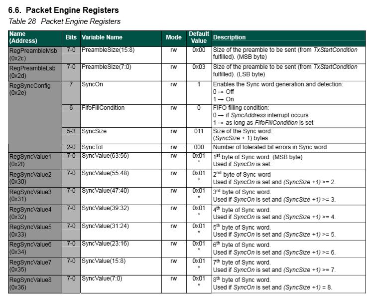
RegPacketConfig1 address filtering options
My first attempt at getting encryption and addressing working together failed badly, the Windows 10 IoT Core device didn’t receive any addressed messages when encryption was enabled. So, I went back and re-read the datasheet again and noticed
“If the address filtering is expected then AddressFiltering must be enabled on the transmitter side as well to prevent address byte to be encrypted”(Sic).
The Arduino client code had to be modified so I could set the node + broadcast address registers and AddressFiltering bit flag in RegPacketConfig1
My RMRFM69.h modifications
enum moduleType {RFM65, RFM65C, RFM69, RFM69C, RFM69H, RFM69HC};

 #define ADDRESS_NODE_DEFAULT 0x0
 #define ADDRESS_BROADCAST_DEFAULT 0x0
 #define ADDRESSING_ENABLED_NODE 0x2
 #define ADDRESSING_ENABLED_NODE_AND_BROADCAST 0x4

	class RMRFM69
	{
	 public:
		 RMRFM69(SPIClass &spiPort, byte csPin, byte dio0Pin, byte rstPin);
		 modulationType Modulation; //OOK/FSK/GFSK
		 moduleType COB;				//Chip on board
		 uint32_t Frequency;			//unit: KHz
		 uint32_t SymbolTime;			//unit: ns
		 uint32_t Devation;				//unit: KHz
		 word BandWidth;				//unit: KHz
		 byte OutputPower;				//unit: dBm   range: 0-31 [-18dBm~+13dBm] for RFM69/RFM69C
										//            range: 0-31 [-11dBm~+20dBm] for RFM69H/RFM69HC
		 word PreambleLength;			//unit: byte

		 bool CrcDisable; //fasle: CRC enable�� & use CCITT 16bit
						  //true : CRC disable
		 bool CrcMode;	//false: CCITT

		 bool FixedPktLength; //false: for contain packet length in Tx message, the same mean with variable lenth
							  //true : for doesn't include packet length in Tx message, the same mean with fixed length
		 bool AesOn;		  //false:
							  //true:
		 bool AfcOn;		  //false:
							  //true:
		 byte SyncLength;	 //unit: none, range: 1-8[Byte], value '0' is not allowed!
		 byte SyncWord[8];
		 byte PayloadLength; //PayloadLength is need to be set a value, when FixedPktLength is true.
		 byte AesKey[16];	//AES Key block, note [0]->[15] == MSB->LSB
		 byte AddressNode = ADDRESS_NODE_DEFAULT;
		 byte AddressBroadcast = ADDRESS_BROADCAST_DEFAULT;

		 void vInitialize(void);
		 void vConfig(void);
		 void vGoRx(void);
		 void vGoStandby(void);
		 void vGoSleep(void);
		 bool bSendMessage(byte msg[], byte length);
		 bool bSendMessage(byte Address, byte msg[], byte length);
		 byte bGetMessage(byte msg[]);
		 void vRF69SetAesKey(void);
		 void vTrigAfc(void);

		 void vDirectRx(void);			  //go continuous rx mode, with init. inside
		 void vChangeFreq(uint32_t freq); //change frequency
		 byte bReadRssi(void);			  //read rssi value
		 void dumpRegisters(Stream& out);
My RMRFM69.cpp modifications in vConfig
 if(!CrcDisable)
 	{
 	i += CrcOn;
	if(CrcMode)
		i += CrcCalc_IBM;
	else
		i += CrcCalc_CCITT;
	}

if((AddressNode!=ADDRESS_NODE_DEFAULT) || (AddressBroadcast==ADDRESS_BROADCAST_DEFAULT))
   {
      i += ADDRESSING_ENABLED_NODE;
   }

if((AddressNode!=ADDRESS_NODE_DEFAULT) || (AddressBroadcast!=ADDRESS_BROADCAST_DEFAULT))
  {
     i += ADDRESSING_ENABLED_NODE_AND_BROADCAST;
  }

 vSpiWrite(((word)RegPacketConfig1<<8)+i);
I also validate the lengths of the messages to be sent taking into account whether encryption is enabled\disabled.
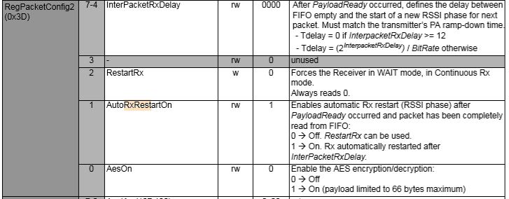
Every so often my Enums & Masks test harness locked up and stopped receiving messages from my test rig. This seemed to happen more often when the send functionality of my library was not being used.
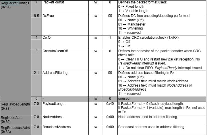
easysensors RFM69HCW test rig
After 5 to 30 minutes (a couple of times it was 5 to 8 hours overnight) the application stopped receiving messages and wouldn’t resume until the application (device reset) was restarted or the RegOpmode-Mode was quickly changed to sleep then back to receive.
I had noticed this code in the Low Power Lab and wondered what it was for. The HopeRF library didn’t appear to have code like this to restart reception which was interesting.
void RFM69::send(uint16_t toAddress, const void* buffer, uint8_t bufferSize, bool requestACK)
{
  writeReg(REG_PACKETCONFIG2, (readReg(REG_PACKETCONFIG2) & 0xFB) | RF_PACKET2_RXRESTART); // avoid RX deadlocks
  uint32_t now = millis();
  while (!canSend() && millis() - now < RF69_CSMA_LIMIT_MS) receiveDone();
  sendFrame(toAddress, buffer, bufferSize, requestACK, false);
}

// should be called immediately after reception in case sender wants ACK
void RFM69::sendACK(const void* buffer, uint8_t bufferSize) {
  ACK_REQUESTED = 0;   // TWS added to make sure we don't end up in a timing race and infinite loop sending Acks
  uint16_t sender = SENDERID;
  int16_t _RSSI = RSSI; // save payload received RSSI value
  writeReg(REG_PACKETCONFIG2, (readReg(REG_PACKETCONFIG2) & 0xFB) | RF_PACKET2_RXRESTART); // avoid RX deadlocks
  uint32_t now = millis();
  while (!canSend() && millis() - now < RF69_CSMA_LIMIT_MS) receiveDone();
  SENDERID = sender;    // TWS: Restore SenderID after it gets wiped out by receiveDone()
  sendFrame(sender, buffer, bufferSize, false, true);
  RSSI = _RSSI; // restore payload RSSI
}

void RFM69::receiveBegin() {
  DATALEN = 0;
  SENDERID = 0;
  TARGETID = 0;
  PAYLOADLEN = 0;
  ACK_REQUESTED = 0;
  ACK_RECEIVED = 0;
#if defined(RF69_LISTENMODE_ENABLE)
  RF69_LISTEN_BURST_REMAINING_MS = 0;
#endif
  RSSI = 0;
  if (readReg(REG_IRQFLAGS2) & RF_IRQFLAGS2_PAYLOADREADY)
    writeReg(REG_PACKETCONFIG2, (readReg(REG_PACKETCONFIG2) & 0xFB) | RF_PACKET2_RXRESTART); // avoid RX deadlocks
  writeReg(REG_DIOMAPPING1, RF_DIOMAPPING1_DIO0_01); // set DIO0 to "PAYLOADREADY" in receive mode
  setMode(RF69_MODE_RX);
}
In the debug output you can see that clock frequencies of the two test devices are slightly different. Every so often they transmit close enough to corrupt one of the message payloads which causes the deadlock.