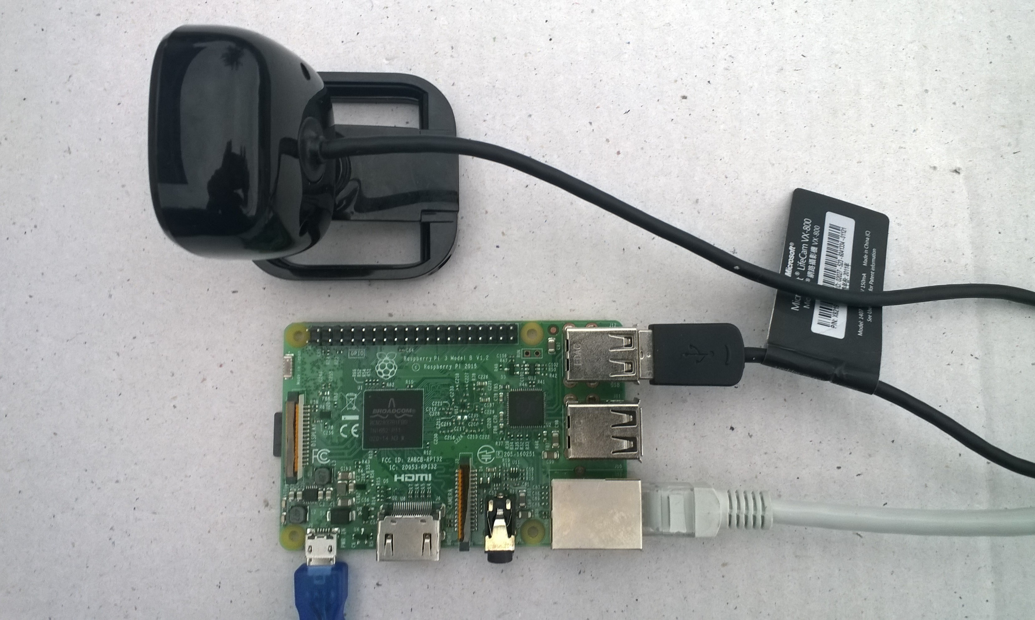
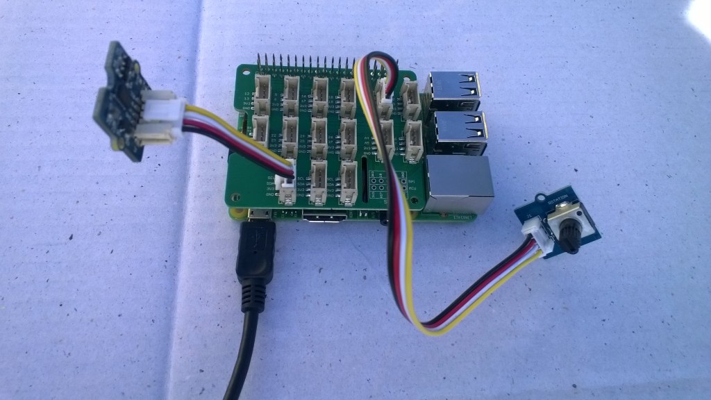
Initiating image capture in response to a trigger was the next step, my plan is to use a button, or a proximity sensor like the passive infrared (PIR) module in the second image to trigger a photo.

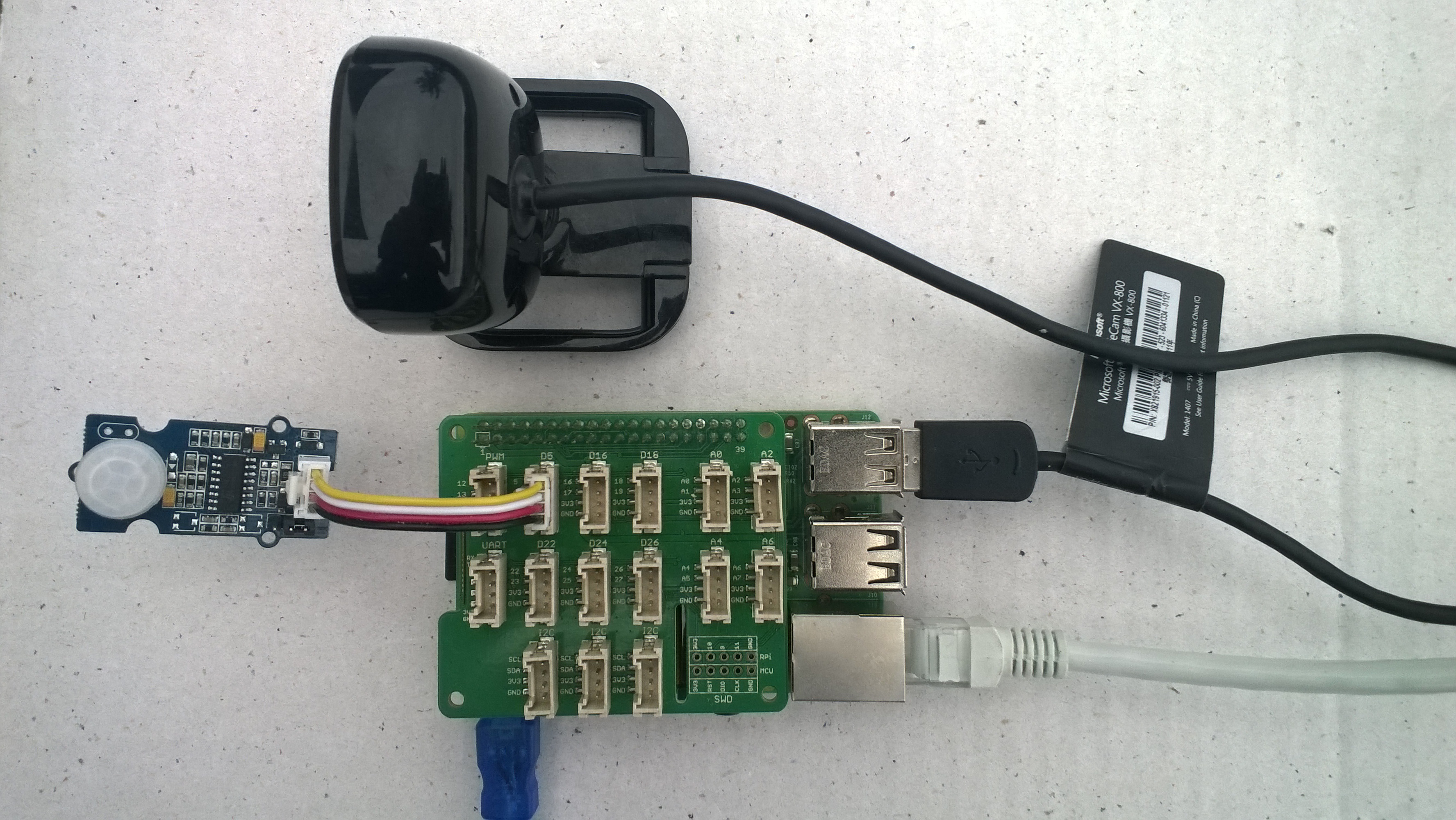
For my test rig (in addition to a RaspberryPI & generic USB Web camera) I’m using some Seeedstudio gear
- Grove Base Hat for Raspberry PI USD9.90
- Grove – Button USD1.90
- Grove – PIR Motion Sensor USD7.90
- Grove – Touch Sensor USD3.90
The first step was to write an interrupt handler for the digital input, I figured triggering on the button push rather than release would make device more responsive.
/*
    Copyright ® 2019 Feb devMobile Software, All Rights Reserved

    MIT License
...
*/
namespace devMobile.Windows10IotCore.IoT.DigitalInputTrigger
{
	using System;
	using System.Diagnostics;
	using Windows.ApplicationModel.Background;
	using Windows.Devices.Gpio;

	public sealed class StartupTask : IBackgroundTask
	{
		private BackgroundTaskDeferral backgroundTaskDeferral = null;
		private GpioPin InterruptGpioPin = null;
		private const int InterruptPinNumber = 5;

		public void Run(IBackgroundTaskInstance taskInstance)
		{
			Debug.WriteLine("Application startup");

			try
			{
				GpioController gpioController = GpioController.GetDefault();

				InterruptGpioPin = gpioController.OpenPin(InterruptPinNumber);
				InterruptGpioPin.SetDriveMode(GpioPinDriveMode.InputPullUp);
				InterruptGpioPin.ValueChanged += InterruptGpioPin_ValueChanged;

				Debug.WriteLine("Digital Input Interrupt configuration success");
			}
			catch (Exception ex)
			{
				Debug.WriteLine($"Digital Input Interrupt configuration failed " + ex.Message);
				return;
			}

			//enable task to continue running in background
			backgroundTaskDeferral = taskInstance.GetDeferral();
		}

		private void InterruptGpioPin_ValueChanged(GpioPin sender, GpioPinValueChangedEventArgs args)
		{
			Debug.WriteLine($"{DateTime.UtcNow.ToLongTimeString()} Digital Input Interrupt {sender.PinNumber} triggered {args.Edge}");
		}
	}
}
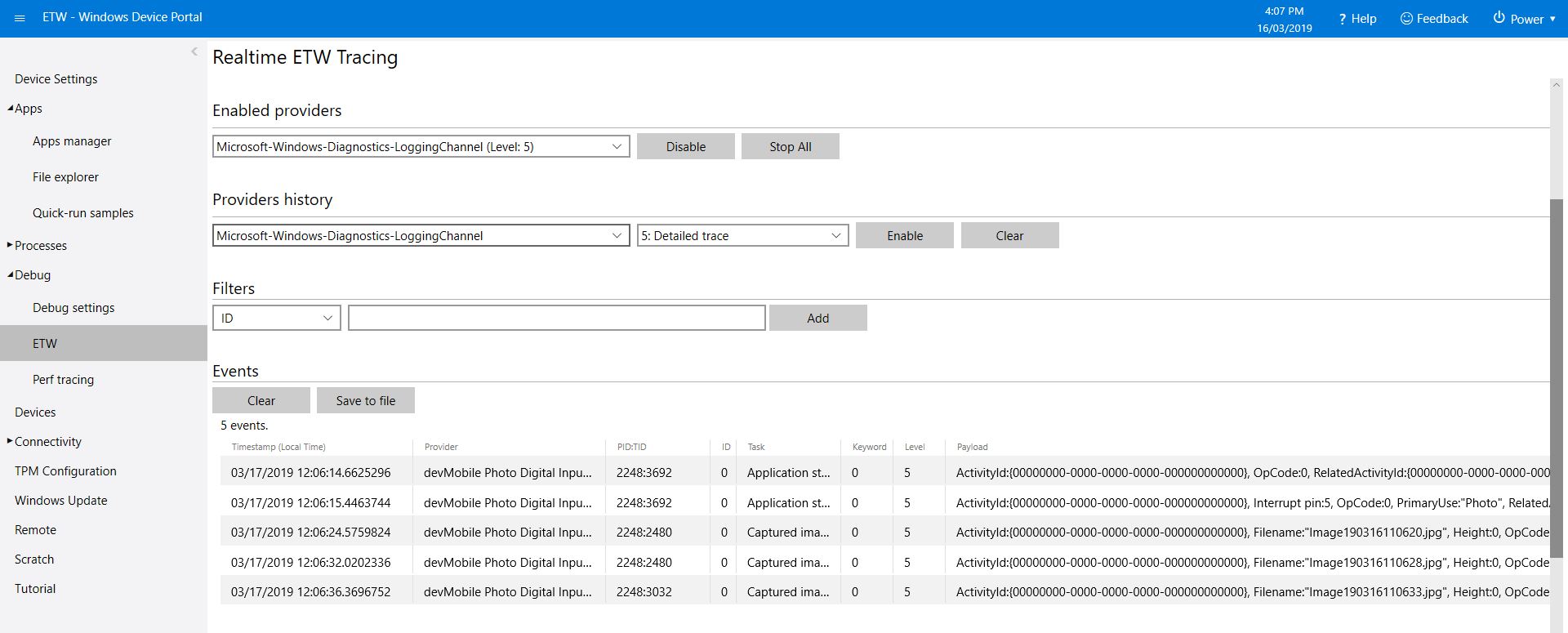
Then I added in the camera functionality and made the interrupt handler async and await the camera and file system calls.
/*
Copyright ® 2019 Feb devMobile Software, All Rights Reserved
MIT License
...
*/
namespace devMobile.Windows10IotCore.IoT.PhotoDigitalInputTrigger
{
using System;
using System.Diagnostics;
using Windows.ApplicationModel.Background;
using Windows.Devices.Gpio;
using Windows.Foundation.Diagnostics;
using Windows.Media.Capture;
using Windows.Media.MediaProperties;
using Windows.Storage;
public sealed class StartupTask : IBackgroundTask
{
private readonly LoggingChannel logging = new LoggingChannel("devMobile Photo Digital Input Trigger demo", null, new Guid("4bd2826e-54a1-4ba9-bf63-92b73ea1ac4a"));
private BackgroundTaskDeferral backgroundTaskDeferral = null;
private GpioPin InterruptGpioPin = null;
private const int InterruptPinNumber = 5;
private MediaCapture mediaCapture;
private const string ImageFilenameFormat = "Image{0:yyMMddhhmmss}.jpg";
private volatile bool CameraBusy = false;
public void Run(IBackgroundTaskInstance taskInstance)
{
LoggingFields startupInformation = new LoggingFields();
this.logging.LogEvent("Application starting");
try
{
mediaCapture = new MediaCapture();
mediaCapture.InitializeAsync().AsTask().Wait();
Debug.WriteLine("Camera configuration success");
GpioController gpioController = GpioController.GetDefault();
InterruptGpioPin = gpioController.OpenPin(InterruptPinNumber);
InterruptGpioPin.SetDriveMode(GpioPinDriveMode.InputPullUp);
InterruptGpioPin.ValueChanged += InterruptGpioPin_ValueChanged;
Debug.WriteLine("Digital Input Interrupt configuration success");
}
catch (Exception ex)
{
this.logging.LogMessage("Camera or digital input configuration failed " + ex.Message, LoggingLevel.Error);
return;
}
startupInformation.AddString("PrimaryUse", mediaCapture.VideoDeviceController.PrimaryUse.ToString());
startupInformation.AddInt32("Interrupt pin", InterruptPinNumber);
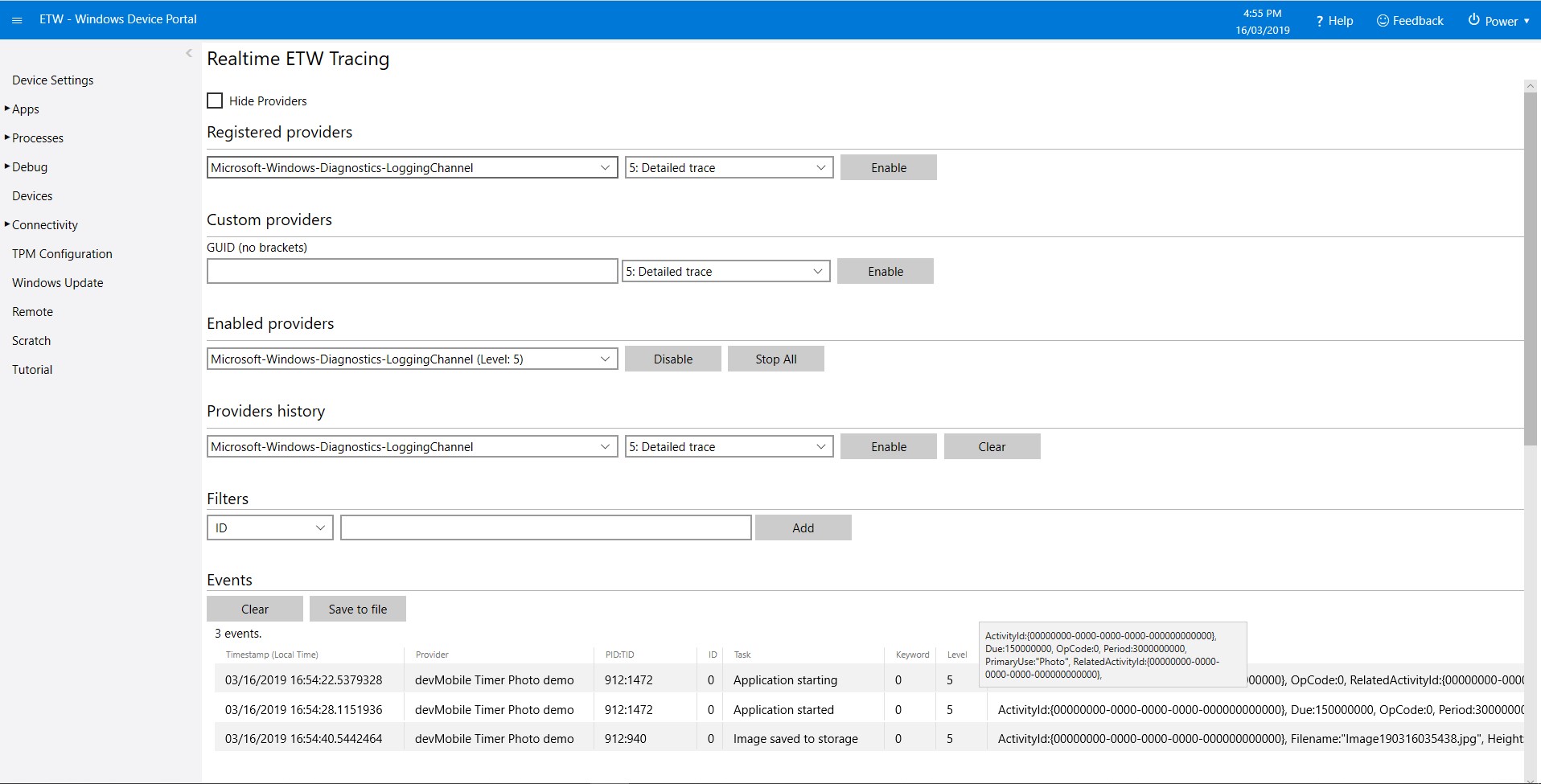
this.logging.LogEvent("Application started", startupInformation);
//enable task to continue running in background
backgroundTaskDeferral = taskInstance.GetDeferral();
}
private async void InterruptGpioPin_ValueChanged(GpioPin sender, GpioPinValueChangedEventArgs args)
{
DateTime currentTime = DateTime.UtcNow;
Debug.WriteLine($"{DateTime.UtcNow.ToLongTimeString()} Digital Input Interrupt {sender.PinNumber} triggered {args.Edge}");
if (args.Edge == GpioPinEdge.RisingEdge)
{
return;
}
// Just incase - stop code being called while photo already in progress
if (CameraBusy)
{
return;
}
CameraBusy = true;
try
{
string filename = string.Format(ImageFilenameFormat, currentTime);
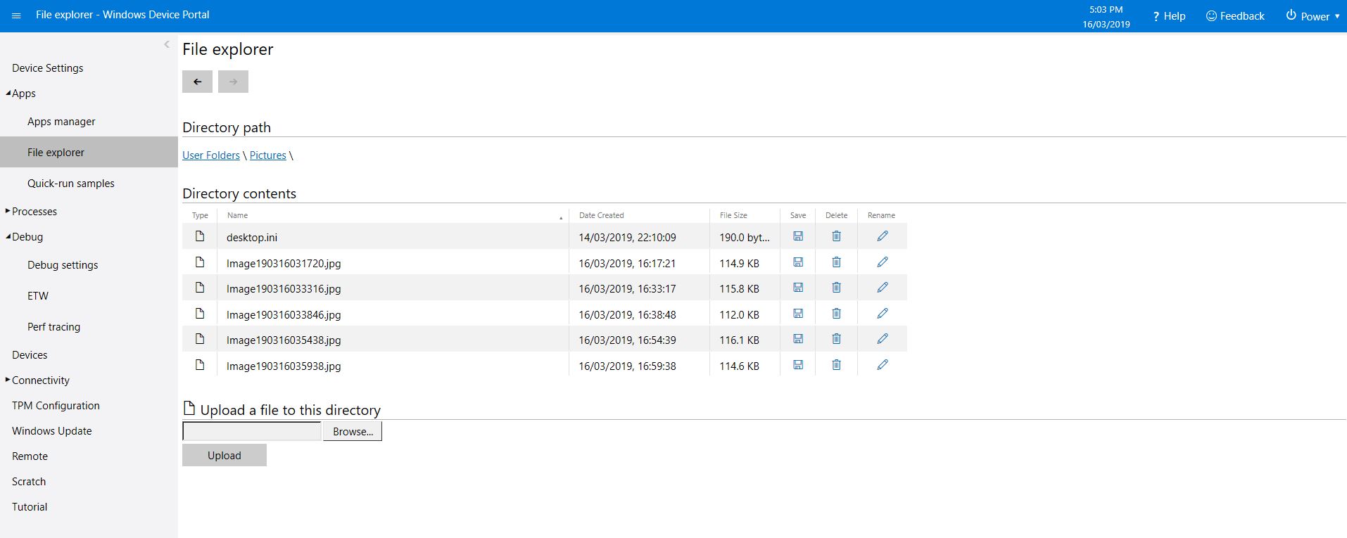
IStorageFile photoFile = await KnownFolders.PicturesLibrary.CreateFileAsync(filename, CreationCollisionOption.ReplaceExisting);
ImageEncodingProperties imageProperties = ImageEncodingProperties.CreateJpeg();
await mediaCapture.CapturePhotoToStorageFileAsync(imageProperties, photoFile);
LoggingFields imageInformation = new LoggingFields();
imageInformation.AddDateTime("TakenAtUTC", currentTime);
imageInformation.AddString("Filename", filename);
imageInformation.AddString("Path", photoFile.Path);
this.logging.LogEvent("Captured image saved to storage", imageInformation);
}
catch (Exception ex)
{
this.logging.LogMessage("Camera photo or save failed " + ex.Message, LoggingLevel.Error);
}
CameraBusy = false;
}
}
}
I found that contactor bounce was an issue (Grove- Touch Sensor OK) with larger mechanical buttons so I added the CameraBusy boolean flag to try and prevent re-entrancy problems. I’ll trial some other types of proximity and beam based on real-world student projects.
The code is available on GitHub and is a bit of a work in progress.