Random wanderings through Microsoft Azure esp. PaaS plumbing, the IoT bits, AI on Micro controllers, AI on Edge Devices, .NET nanoFramework, .NET Core on *nix and ML.NET+ONNX
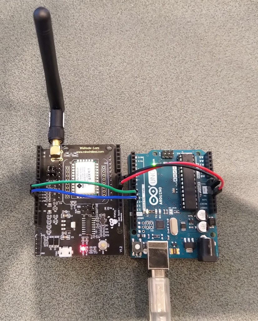
STM32F691Discovery with EVB connected with Jumpers
The STM32F691DISCOVERY board has an Arduino Uno R3 format socket which I wanted to be able to plug the EVB into. After removing R8,R17 & R19 I put the EVB on the STM32F691DISCOVERY and could still retrieve the RAK811 module version information.
STM32F691Discovery with EVB plugged into Arduino headers
The thread '<No Name>' (0x2) has exited with code 0 (0x0).
devMobile.IoT.Rfm9x.ShieldSerial starting
COM5,COM6
TX: 12 bytes to output stream.
TX: 12 bytes via COM6
RXs :19 bytes read from COM6
RX sync:OK V3.0.0.13.H.T3

TX: 12 bytes to output stream.
TX: 12 bytes via COM6
RXs :19 bytes read from COM6
RX sync:OK V3.0.0.13.H.T3
I wanted the RAK811 LPWAN Evaluation Board(EVB) -AS923 to work with selection of my Arduino and nanoFramework devices. The first decision was which of the hardware serial port (D0,D1) or the software serial port (D10,D11) should be connected to P1?
To use the EVB with my STM32F691DISCOVERY board running the nanoFramework (COM5 on the hardware serial port pins D0,D1) I removed R17&R19.
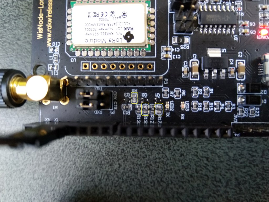
After some tinkering, I found that R8 which is connected to the RAK811 module reset had to be cut as well for the shield to work on my Arduino Uno R3 and STM32F691DISCOVERY devices.
RAK811 EVB with R17,R19 & R8 cut
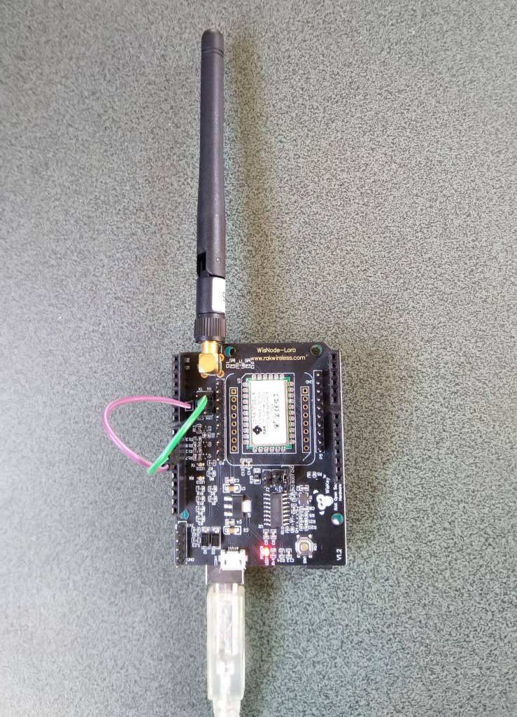
I can still run the Arduino Uno R3 and RAK811 EVB in the original configuration with a couple of jumper leads
RAK811 on Arduino with Serial connected to D10,D1 a SoftwareSerial port
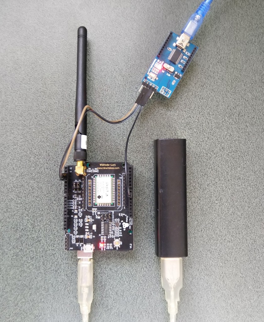
For devices where I needed D10,D11 for a Serial Peripheral Interface(SPI) I could use an FTDI board and a couple of other pins (in this case D2,D3) for serial logging.
RAK811 on Arduino with Serial connected to D2,D2 a SoftwareSerial port
After debugging some code I also replaced the small jumpers on P1 with a couple of jumper leads so it was less fiddly to swap from downloading to debugging.
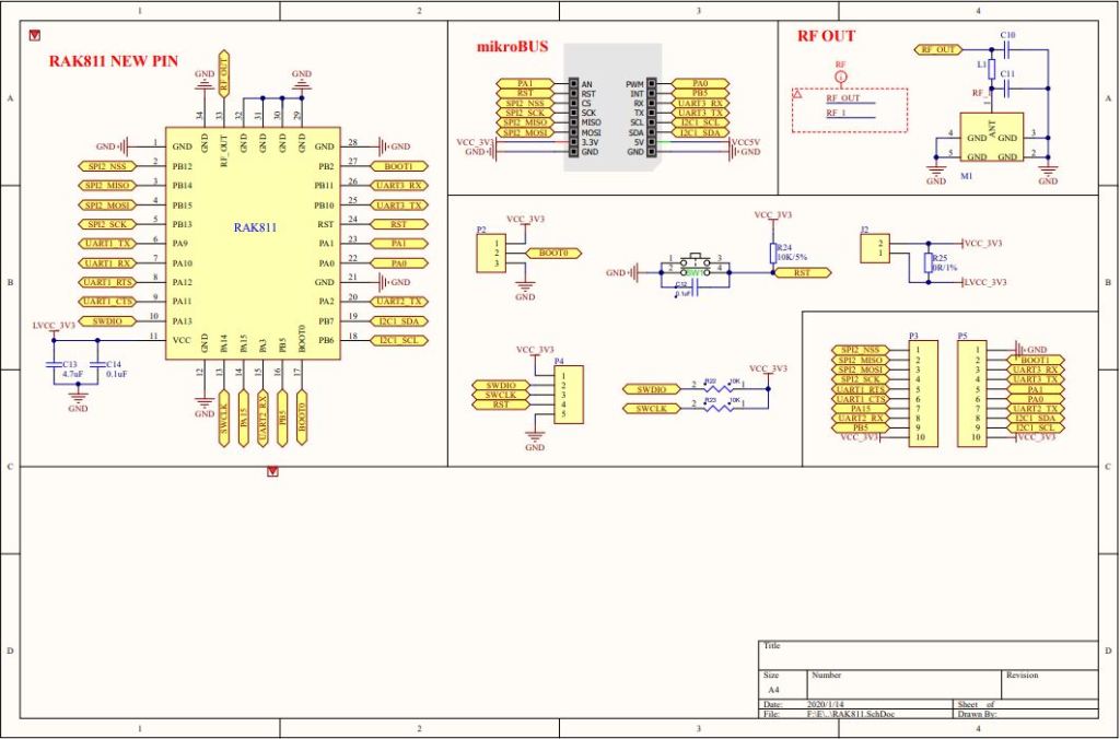
My first step was to check what serial ports were available (COM5 & COM6) on the STM32F691Discovery and what pins they were connected to. (COM6 Arduino D0 & D1). Then check that these would work with the EVB pin assignments.
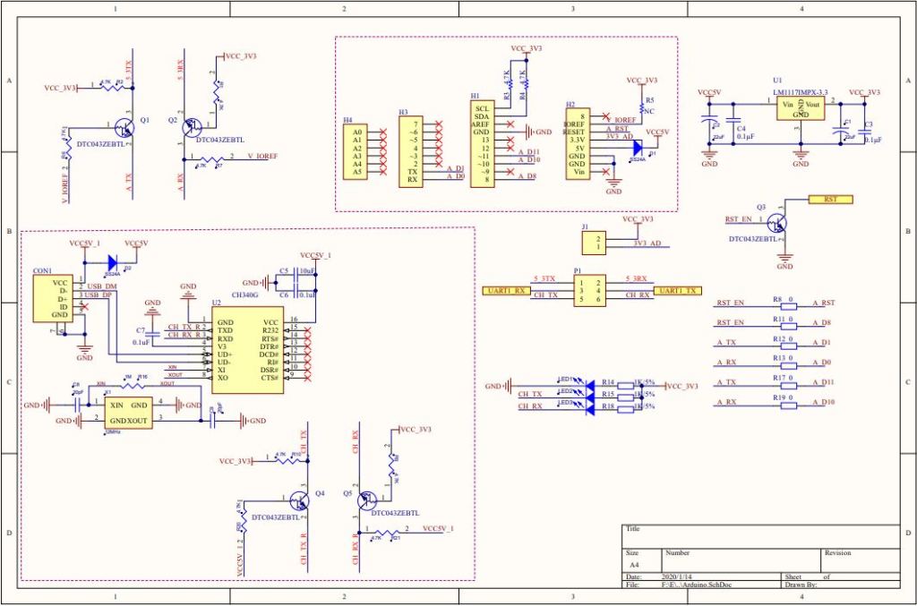
RAK 811 EVB schematic pg1RAK 811 EVB schematic pg2
My first test was was a simple loopback based on the nanoFramework samples Serial Communications example.
STM32F691Discovery with jumper loopback
//---------------------------------------------------------------------------------
// Copyright (c) June 2020, devMobile Software
//
// Licensed under the Apache License, Version 2.0 (the "License");
// you may not use this file except in compliance with the License.
// You may obtain a copy of the License at
//
//     http://www.apache.org/licenses/LICENSE-2.0
//
// Unless required by applicable law or agreed to in writing, software
// distributed under the License is distributed on an "AS IS" BASIS,
// WITHOUT WARRANTIES OR CONDITIONS OF ANY KIND, either express or implied.
// See the License for the specific language governing permissions and
// limitations under the License.
//
//---------------------------------------------------------------------------------
//#define ESP32_WROOM   //nanoff --target ESP32_WROOM_32 --serialport COM4 --update
//#define NETDUINO3_WIFI   // nanoff --target NETDUINO3_WIFI --update
//#define MBN_QUAIL // nanoff --target MBN_QUAIL --update
//#define ST_NUCLEO64_F091RC // nanoff --target ST_NUCLEO64_F091RC --update
//#define ST_NUCLEO144_F746ZG //nanoff --target ST_NUCLEO144_F746ZG --update
#define ST_STM32F769I_DISCOVERY      // nanoff --target ST_STM32F769I_DISCOVERY --update
namespace devMobile.IoT.Rak811.ShieldSerial
{
   using System;
   using System.Diagnostics;
   using System.Threading;
   using Windows.Devices.SerialCommunication;
   using Windows.Storage.Streams;

#if ESP32_WROOM_32_LORA_1_CHANNEL
   using nanoFramework.Hardware.Esp32;
#endif

   public class Program
   {
#if ESP32_WROOM
      private const string SerialPortId = "";
#endif
#if NETDUINO3_WIFI
      private const string SpiBusId = "";
#endif
#if MBN_QUAIL
      private const string SpiBusId = "";
#endif
#if ST_NUCLEO64_F091RC
      private const string SpiBusId = "";
#endif
#if ST_NUCLEO144_F746ZG
      private const string SpiBusId = "";
#endif
#if ST_STM32F429I_DISCOVERY
      private const string SpiBusId = "";
#endif
#if ST_STM32F769I_DISCOVERY
      private const string SerialPortId = "COM6";
#endif

      public static void Main()
      {
         SerialDevice serialDevice;

         Debug.WriteLine("devMobile.IoT.Rfm9x.ShieldSerial starting");

         Debug.WriteLine(Windows.Devices.SerialCommunication.SerialDevice.GetDeviceSelector());

         try
         {
            // set GPIO functions for COM2 (this is UART1 on ESP32)
            #if ESP32_WROOM
               Configuration.SetPinFunction(Gpio.IO04, DeviceFunction.COM2_TX);
               Configuration.SetPinFunction(Gpio.IO05, DeviceFunction.COM2_RX);
            #endif
            serialDevice = SerialDevice.FromId(SerialPortId);

            // set parameters
            serialDevice.BaudRate = 9600;
            serialDevice.Parity = SerialParity.None;
            serialDevice.StopBits = SerialStopBitCount.One;
            serialDevice.Handshake = SerialHandshake.None;
            serialDevice.DataBits = 8;

            serialDevice.ReadTimeout = new TimeSpan(0, 0, 30);
            serialDevice.WriteTimeout = new TimeSpan(0, 0, 4);

            DataWriter outputDataWriter = new DataWriter(serialDevice.OutputStream);

            #if SERIAL_SYNC_READ
               DataReader inputDataReader = new DataReader(serialDevice.InputStream);
            #else
               serialDevice.DataReceived += SerialDevice_DataReceived;
            #endif

            // set a watch char to be notified when it's available in the input stream
            serialDevice.WatchChar = '\n';

            while (true)
            {
               uint bytesWritten = outputDataWriter.WriteString("at+version\r\n");
               Debug.WriteLine($"TX: {outputDataWriter.UnstoredBufferLength} bytes to output stream.");

               // calling the 'Store' method on the data writer actually sends the data
               uint txByteCount = outputDataWriter.Store();
               Debug.WriteLine($"TX: {txByteCount} bytes via {serialDevice.PortName}");

#if SERIAL_SYNC_READ
               uint bytesRead = inputDataReader.Load(50);

               Debug.WriteLine($"RXs :{bytesRead} bytes read from {serialDevice.PortName}");

               if (bytesRead > 0)
               {
                  String response = inputDataReader.ReadString(bytesRead);
                  Debug.WriteLine($"RX sync:{response}");
               }
#endif

               Thread.Sleep(20000);
            }
         }
         catch (Exception ex)
         {
            Debug.WriteLine(ex.Message);
         }
      }

      private static void SerialDevice_DataReceived(object sender, SerialDataReceivedEventArgs e)
      {
         switch(e.EventType)
         {
            case SerialData.Chars:
               //Debug.WriteLine("RX SerialData.Chars");
               break;

            case SerialData.WatchChar:
               Debug.WriteLine("RX: SerialData.WatchChar");
               SerialDevice serialDevice = (SerialDevice)sender;

               using (DataReader inputDataReader = new DataReader(serialDevice.InputStream))
               {
                  inputDataReader.InputStreamOptions = InputStreamOptions.Partial;

                  // read all available bytes from the Serial Device input stream
                  uint bytesRead = inputDataReader.Load(serialDevice.BytesToRead);

                  Debug.WriteLine($"RXa: {bytesRead} bytes read from {serialDevice.PortName}");

                  if (bytesRead > 0)
                  {
                     String response = inputDataReader.ReadString(bytesRead);
                     Debug.WriteLine($"RX:{response}");
                  }
               }
               break;
            default:
               Debug.Assert(false, $"e.EventType {e.EventType} unknown");
               break;
         }
      }
   }
}
After some tinkering I could successfully transmit and receive a string.
The next step was to connect my EVB and sent the AT Command to request the LoRaWAN module version information
STM32F691Discovery with EVB connected with Jumpers
The thread '<No Name>' (0x2) has exited with code 0 (0x0).
devMobile.IoT.Rfm9x.ShieldSerial starting
COM5,COM6
TX: 12 bytes to output stream.
TX: 12 bytes via COM6
RX: SerialData.WatchChar
RXa: 19 bytes read from COM6
RX:OK V3.0.0.13.H.T3

TX: 12 bytes to output stream.
TX: 12 bytes via COM6
RX: SerialData.WatchChar
RXa: 19 bytes read from COM6
RX:OK V3.0.0.13.H.T3
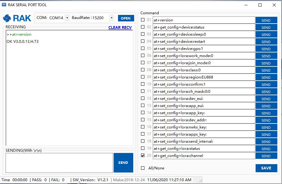
The response was the same as I got with the RAK Serial Port Tool which was positive.
Version number check with RAK Serial Port tool
I need to do some more digging into how serialDevice.WatchChar = ‘\n’ works for synchronous reads.
Plus removing R17 & R19 there is no interaction with D11 & D10 which are normally used by the Serial Peripheral Interface(SPI) port so I can plug the shield directly into the STM32F691Discovery board.
My plan was to get an initial version of the library working with the STM32F691Discovery, then port it to the Netduino 3 Wifi (possible serial port pin issues) , ST_NUCLEO144_F746ZG, and ST_NUCLEO64_F091RC (possible issues with available flash).
Just over a week ago I purchased a RAK811 LPWAN Evaluation Board -AS923 and now I want to trial it with selection of devices and configurations.
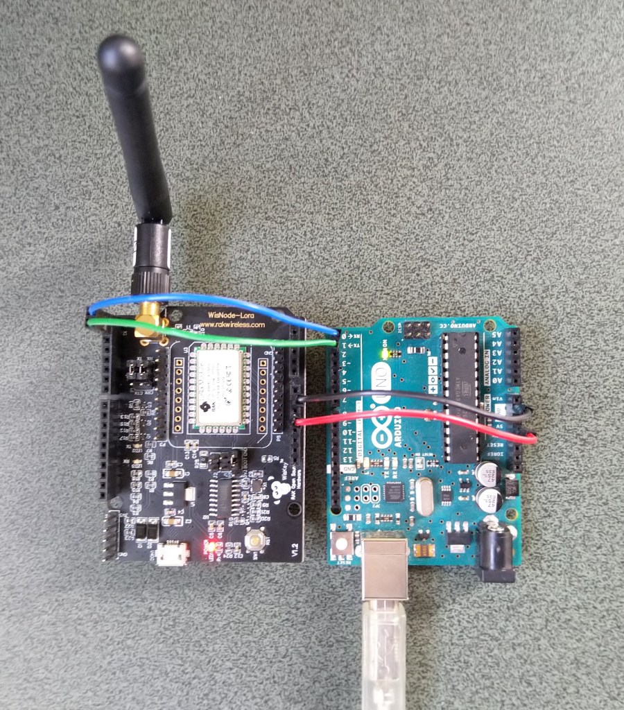
Initially I didn’t want to modify the shield by removing resistors as I only have one, and I’m not certain what device(s) it will be used with. The initial hardware configuration required jumpers for the serial port, ground and 5V power.
Arduino Uno R3 and RAK811 LPWAN Evaluation board 5V config
After looking at the schematic it should be possible to use the shield with a 3v3 device.
RAK 811 EVB schematic pg1RAK 811 EVB schematic pg2
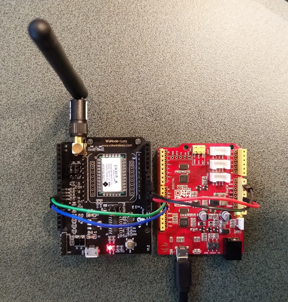
I confirmed this with a Seeeduino V4.2 devices set to 3v3, by putting a jumper on J1 and shifting the jumper wire from the 5V to the 3V3 pin.
Seeeduino V4 and RAK811 LPWAN Evaluation board 3V3 config
The next step was to see how I could get the RAK shield working on other devices without jumpers. On Arduino Uno R3 devices D0&D1 are the hardware(HW) serial port which are used for uploading sketches, and diagnostic logging.
The shield also connects the module serial port to D0&D1 to D10&D11, so by removing R17&R19 the shield should work on a device This would also allow the use of the Serial Peripheral Interface(SPI) port for other applications.
Using the HW Serial port but without any logging.
Unplugging the jumpers to upload was painful but the lack of logging made it really hard to debug my code.
To get around this I configured a SoftwareSerial port on D2&D3 for logging.
/********************************************************
* This demo is only supported after RUI firmware version 3.0.0.13.X on RAK811
* Master Board Uart Receive buffer size at least 128 bytes.
********************************************************/
//#define SERIAL_BUFFER_SIZE 128
//#define SERIAL_TX_BUFFER_SIZE 64
//#define SERIAL_RX_BUFFER_SIZE 128
//#define _SS_MAX_RX_BUFF 128
#include "RAK811.h"
#include "SoftwareSerial.h"
#define WORK_MODE LoRaWAN // LoRaWAN or LoRaP2P
#define JOIN_MODE OTAA // OTAA or ABP
#if JOIN_MODE == OTAA
String DevEui = "..."; // From TTN
String AppEui = "...";
String AppKey = "...";
#else JOIN_MODE == ABP
String NwkSKey = "...";
String AppSKey = "...";
String DevAddr = "...";
#endif
#define TXpin 3 // Set the virtual serial port pins
#define RXpin 2
SoftwareSerial DebugSerial(RXpin,TXpin); // Declare a virtual serial port for debugging
#define ATSerial Serial
char buffer[]= "48656C6C6F20776F726C6435";
bool InitLoRaWAN(void);
RAK811 RAKLoRa(ATSerial,DebugSerial);
void setup() {
DebugSerial.begin(19200);
DebugSerial.println(F("Starting"));
while(DebugSerial.available())
{
DebugSerial.read();
}
ATSerial.begin(9600); //set ATSerial baudrate:This baud rate has to be consistent with the baud rate of the WisNode device.
while(ATSerial.available())
{
ATSerial.read();
}
if(!RAKLoRa.rk_setWorkingMode(0)) //set WisNode work_mode to LoRaWAN.
{
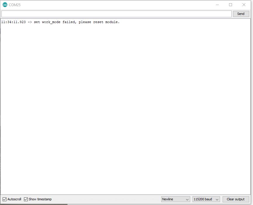
DebugSerial.println(F("set work_mode failed, please reset module."));
while(1);
}
RAKLoRa.rk_getVersion(); //get RAK811 firmware version
DebugSerial.println(RAKLoRa.rk_recvData()); //print version number
DebugSerial.println(F("Start init RAK811 parameters..."));
if (!InitLoRaWAN()) //init LoRaWAN
{
DebugSerial.println(F("Init error,please reset module."));
while(1);
}
DebugSerial.println(F("Start to join LoRaWAN..."));
while(!RAKLoRa.rk_joinLoRaNetwork(60)) //Joining LoRaNetwork timeout 60s
{
DebugSerial.println();
DebugSerial.println(F("Rejoin again after 5s..."));
delay(5000);
}
DebugSerial.println(F("Join LoRaWAN success"));
if(!RAKLoRa.rk_isConfirm(0)) //set LoRa data send package type:0->unconfirm, 1->confirm
{
DebugSerial.println(F("LoRa data send package set error,please reset module."));
while(1);
}
}
bool InitLoRaWAN(void)
{
if(RAKLoRa.rk_setJoinMode(JOIN_MODE)) //set join_mode:OTAA
{
if(RAKLoRa.rk_setRegion(0)) //set region EU868
{
if (RAKLoRa.rk_initOTAA(DevEui, AppEui, AppKey))
{
DebugSerial.println(F("RAK811 init OK!"));
return true;
}
}
}
return false;
}
void loop()
{
DebugSerial.println(F("Start send data..."));
if (RAKLoRa.rk_sendData(1, buffer))
{
//for (unsigned long start = millis(); millis() - start < 300000L;)
for (unsigned long start = millis(); millis() - start < 10000L;)
{
String ret = RAKLoRa.rk_recvData();
if(ret != NULL)
{
DebugSerial.println("ret != NULL");
DebugSerial.println(ret);
}
if((ret.indexOf("OK")>0)||(ret.indexOf("ERROR")>0))
{
DebugSerial.println(F("Go to Sleep."));
RAKLoRa.rk_sleep(1); //Set RAK811 enter sleep mode
delay(10000); //delay 10s
RAKLoRa.rk_sleep(0); //Wakeup RAK811 from sleep mode
break;
}
}
}
}
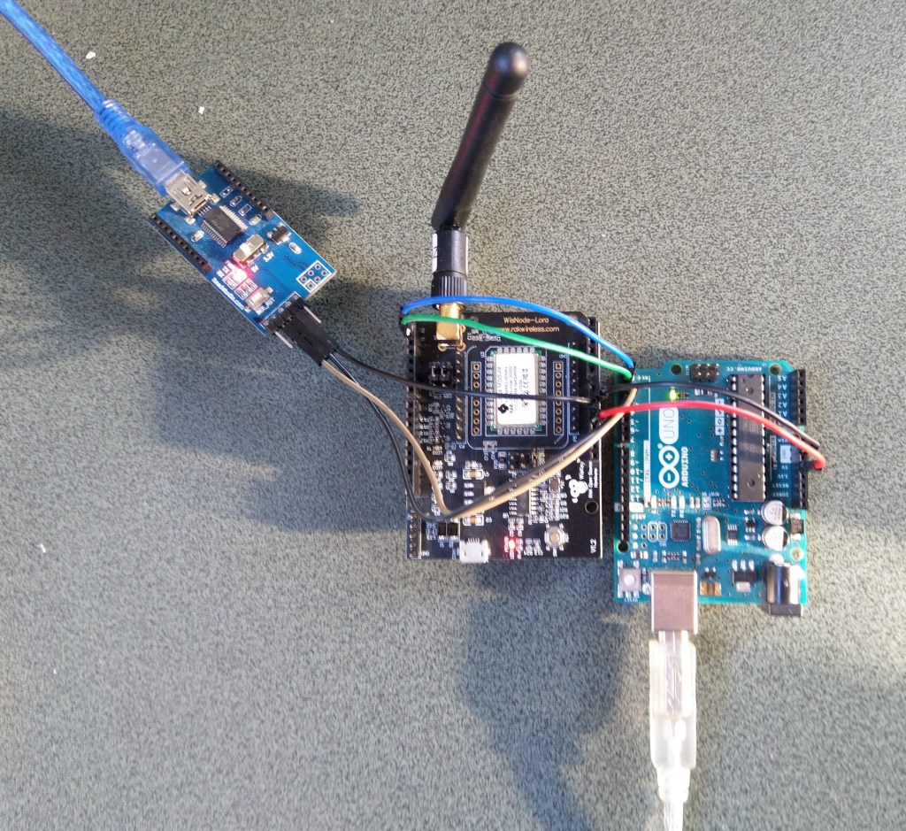
I used an FTDI module I had lying around to connect the diagnostic logging serial port on the test rig to my development box.
Using the HW Serial port but with logging.
Now I only had to unplug the jumpers for D0&D1 and change ports in the Arduino IDE. One port for debugging the other for downloading.
Depending on the application I may remove R8 so I can manually reset the shield.
The evaluation board was in its own box along with a USB cable, some spare PCB jumpers, some jumper leads and an antenna labeled with the frequency band which was thoughtful.
Arduino Uno R3 and RAK811 LPWAN Evaluation board 5V config
I downloaded the specified library from the RAK Wireless Github repository extracted the contents and copied the V1.3 directory into the libraries folder of my Arduino IDE install.
I updated the module software to the latest using the tools provided in the github download and checked this with the RAK Serial Port tool over the Universal Serial Bus(USB) connection (make sure the jumpers next to the antenna connection are set correctly)
I then had a look at the Arduino library code and enabled some of the commented out diagnostic println statements. At the time it did seem odd there were no responses from the module.
Arduino monitor output showing rk_setWorkingMode failing with debugging
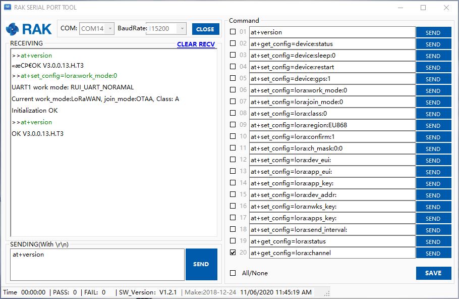
I had noticed some odd characters in the RAK Serial Port Tool while checking version numbers etc.
Setting work Mode with RAK Serial Port Tool
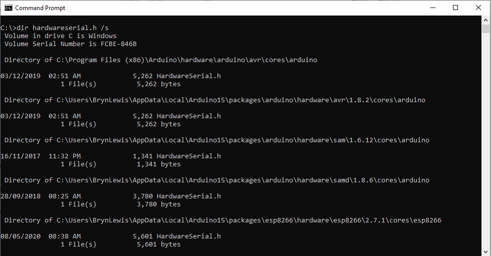
It looked like maybe the serial port was having some issues, so I double checked my modification of the HardwareSerial.h file and began to wonder (as the binary size wasn’t changing) if I had the right file. After some research I found there are several copies of that file and I wasn’t modifying the correct one.
Multiple locations of HardwareSerial.h
Then I realised that the port sending AT Commands to the module was actually a SoftwareSerial port not a hardware one. I then tried changing the size of the software serial buffers but still was having problems.
Arduino tool with default buffer sizes (833 bytes)Arduino tool with non-default buffer sizes (961 bytes)
I then tried recompiling with different settings to see if the serial port issues would stop. The global variables size changed which showed I had the right files/settings but the code still didn’t work.
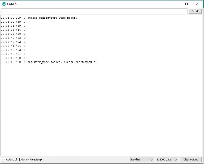
Going back over my settings I tried the command used in the rk_setWorkingMode call in the RAK Serial Port Tool and it worked.
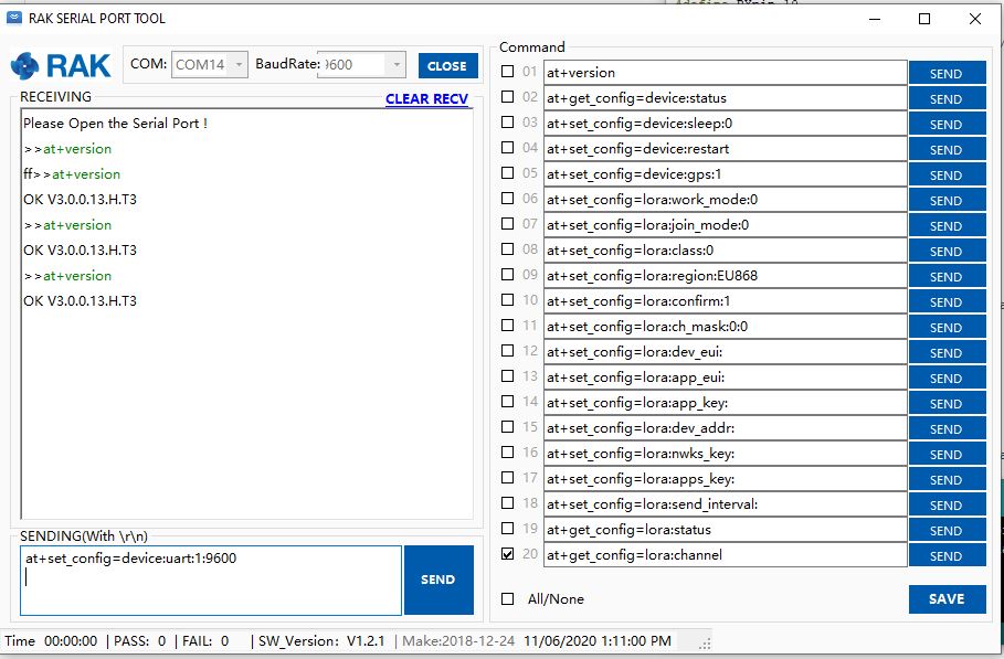
I then then went for a walk and when I came back I realised the module speed was set to 115200 baud by default (which it is). I then used at+set_config=device:uart:1:9600 (don’t forget to press <enter> at end of the line) to set baud rate to match the code.
Setting device to 9600 baud
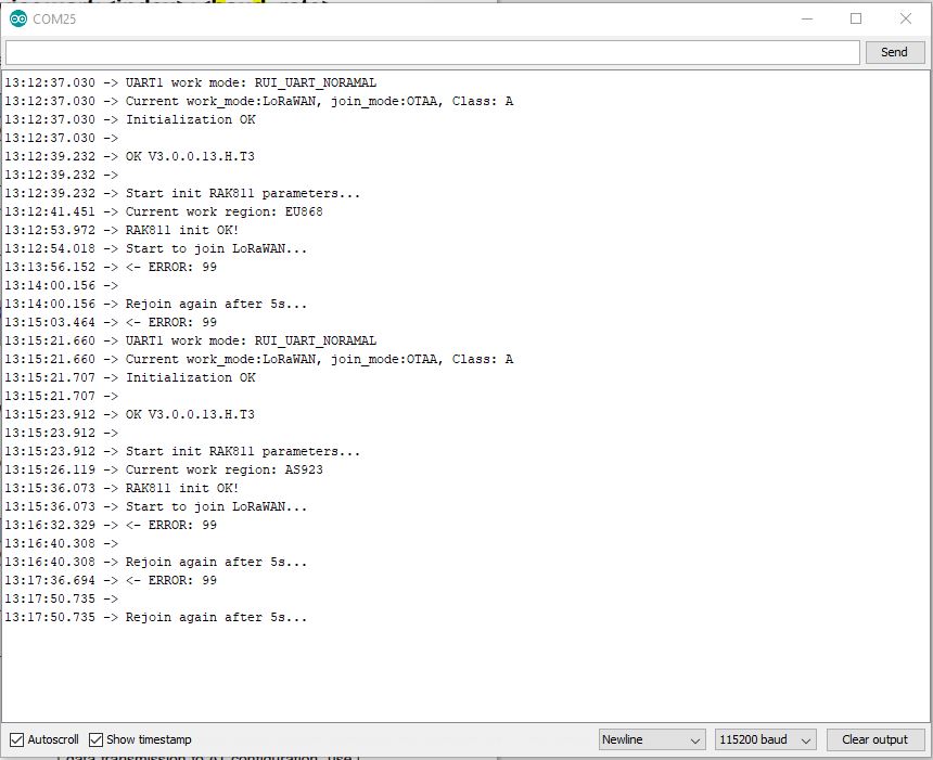
I then changed the jumpers and ran the software again…
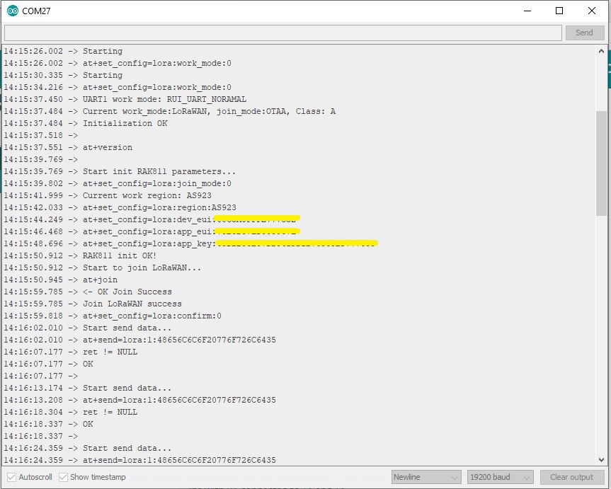
So, it looks like the RAK811 module was set to 115200 baud (web based setup instructions), but the later library versions were 9600 baud, but the instructions didn’t mention the need to change the speed with the RAK Serial port tool.
Image of code and setup from RAK instructions
Now that my device is trying to connect to a network I need to configure the LoRaWAN network settings. I’m going to use the RAK7246G LPWAN Developer Gateway and the nationwide LoRaWAN network operated by Spark in New Zealand.